AmTryke 2700 Series - 24”Model # 50-2721, 20” Model #50-2701
Revise Date: 9/05/08 Page 5 of 23
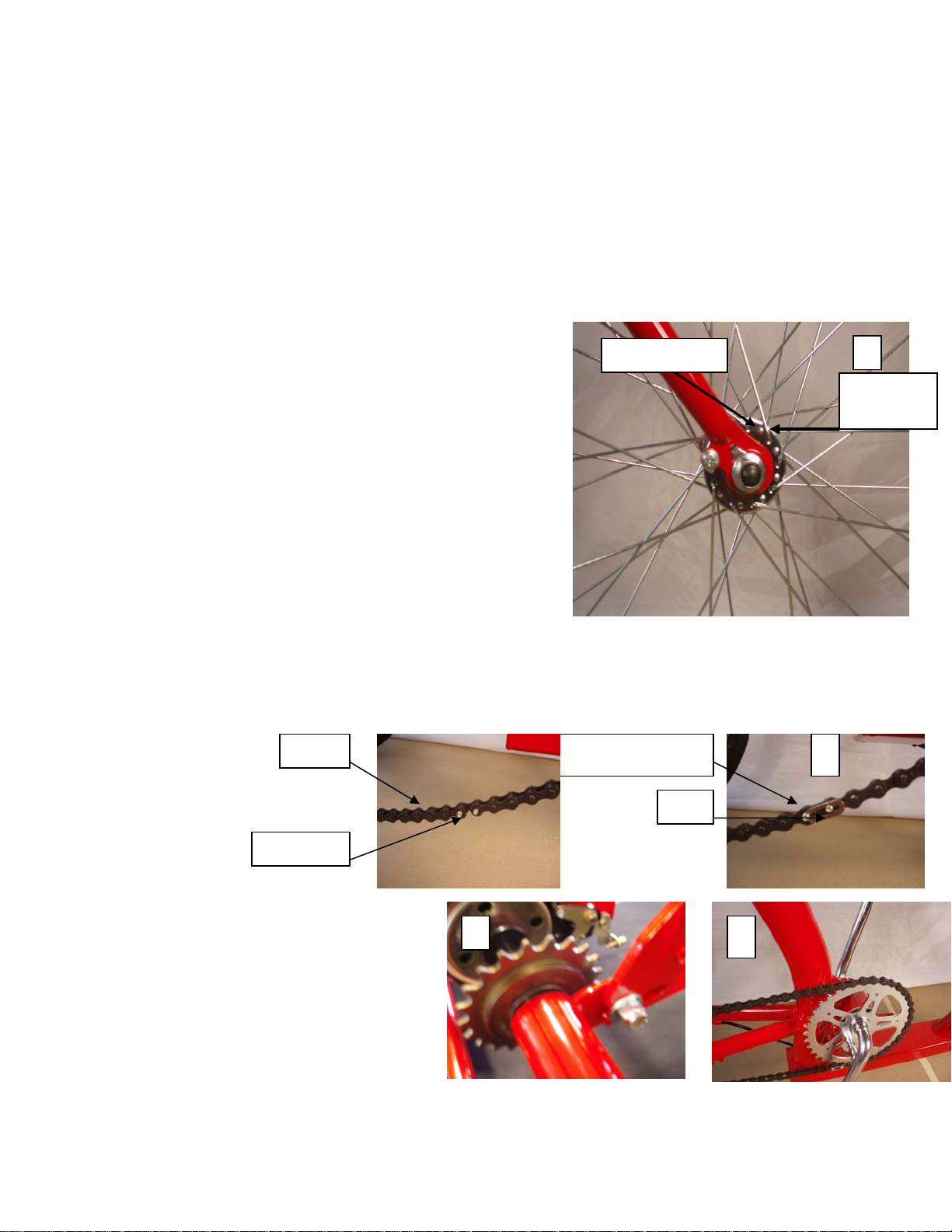
d) The chain should be very loose and have plenty of slack in it. Slide the retaining link (resembles a figure
eight) over the two exposed chain link pins.
e) With open end of the clip pointing towards the back of the tryke, slide the clip over one pin. Align the
open end of the clip with the other pin. Using a pair of needle nose pliers grasp the closed end of the clip
and the front pin of the chain link and compress until clip surrounds both chain pins. CAUTION:
FAILURE TO INSTALL CHAIN CORRECTLY CAN RESULT IN THE CHAIN COMING OFF.
f) Thread chain over rear wheel sprocket, you can spin the right rear wheel to aide in the installation.
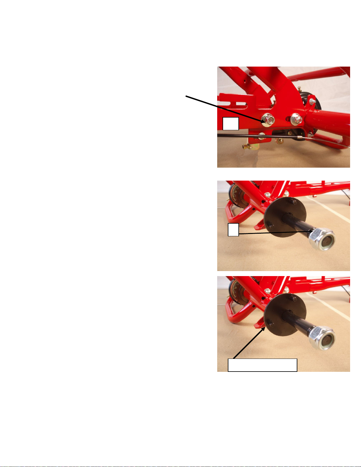
g) Loosen the one bolt nut on the rear deck that you hand tightened from Step 1 (d). Pull back on rear
wheel deck until chain is tight. Chain should only have ½” of play up and down.
h) Tighten the four 14mm rear deck nuts now (refer to Step 1 (d) and (e)) securely.
CAUTION: THE FOUR 14MM REAR DECK NUTS MUST BE TIGHTENED SECURELY BEFORE
RIDING THE AMTRYKE.
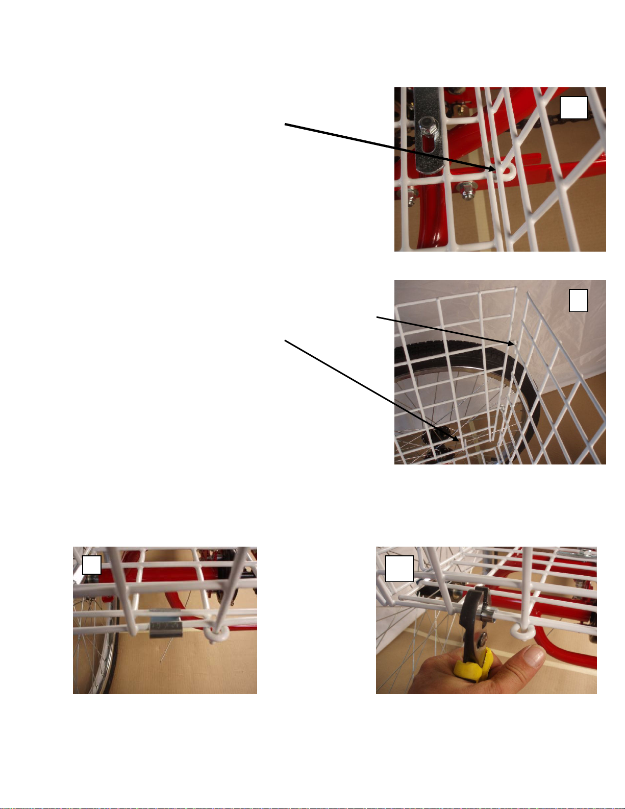
5) Basket Assembly
The basket has four sides, one bottom, eight metal clips, two flat metal straps, four bolts, four nuts and eight
washers. You will need a 12mm and a 13mm wrench or socket and a pair of pliers to install.
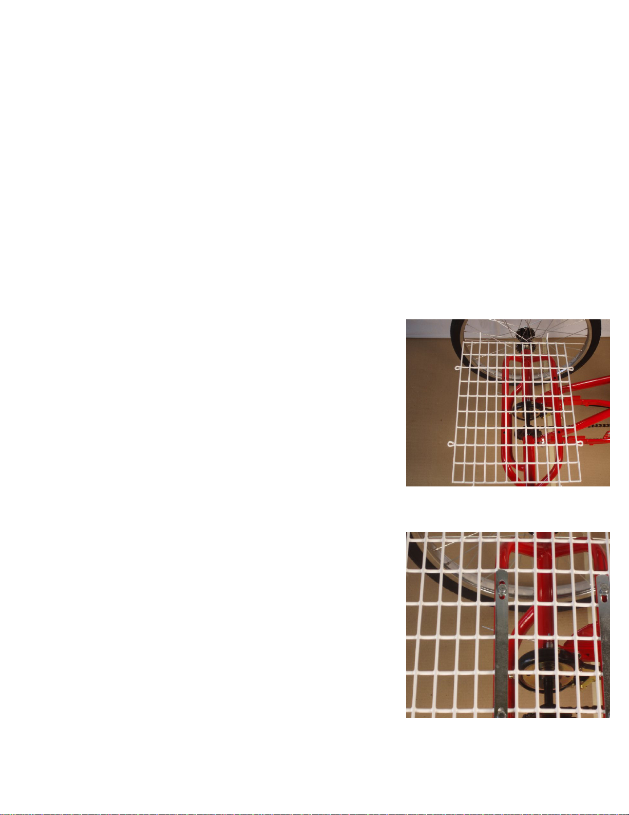
a) Basket Bottom
Lay the bottom of the basket on the rear deck with the tabs sticking
upright and centered between the two rear wheels. Make sure that it
is not resting against the angled portion of the main frame of the
bike.
b) Install metal straps
You will need the two flat metal straps, the four bolts, the four nuts
and the eight washers. Lay flat metal straps over bottom of basket so
that it aligns with the holes drilled in rear deck, slide one washer
over each bolt, insert bolts through flat metal straps and through
holes in rear deck frame. Install one washer and nut on each bolt on
the underside of support frame. Be sure the bottom of basket is
centered, and then tighten bolts/ nuts with 12mm and 13mm sockets
or wrenches.