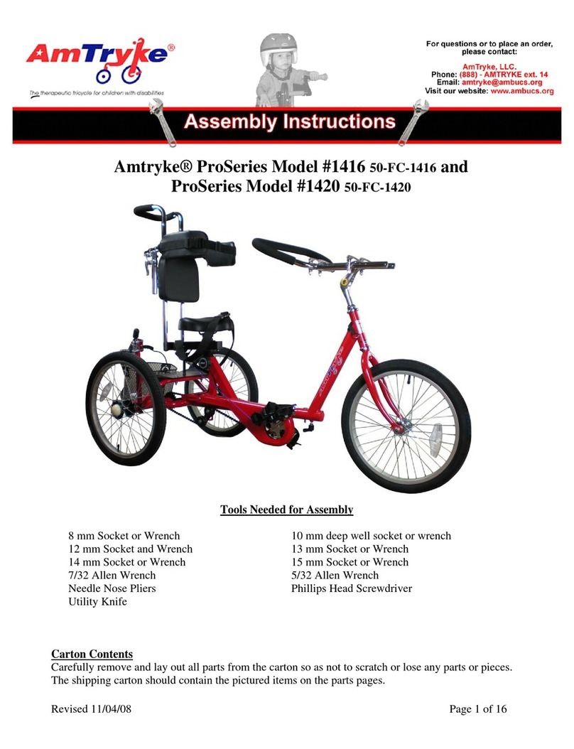
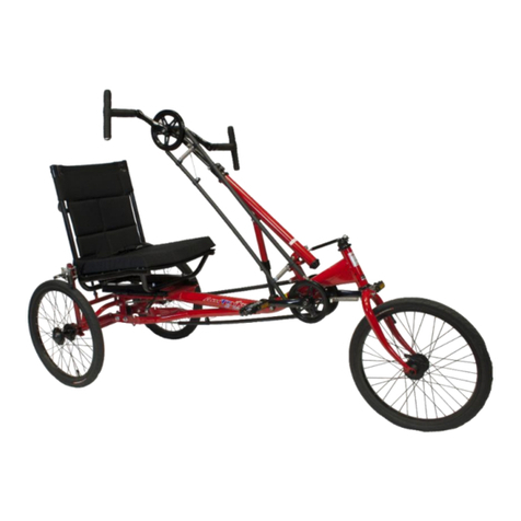
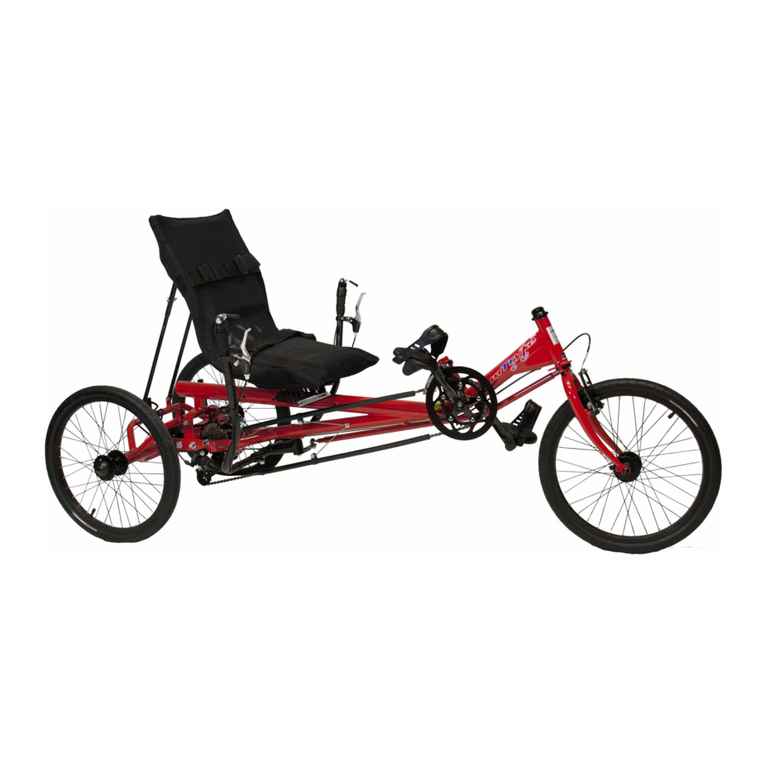
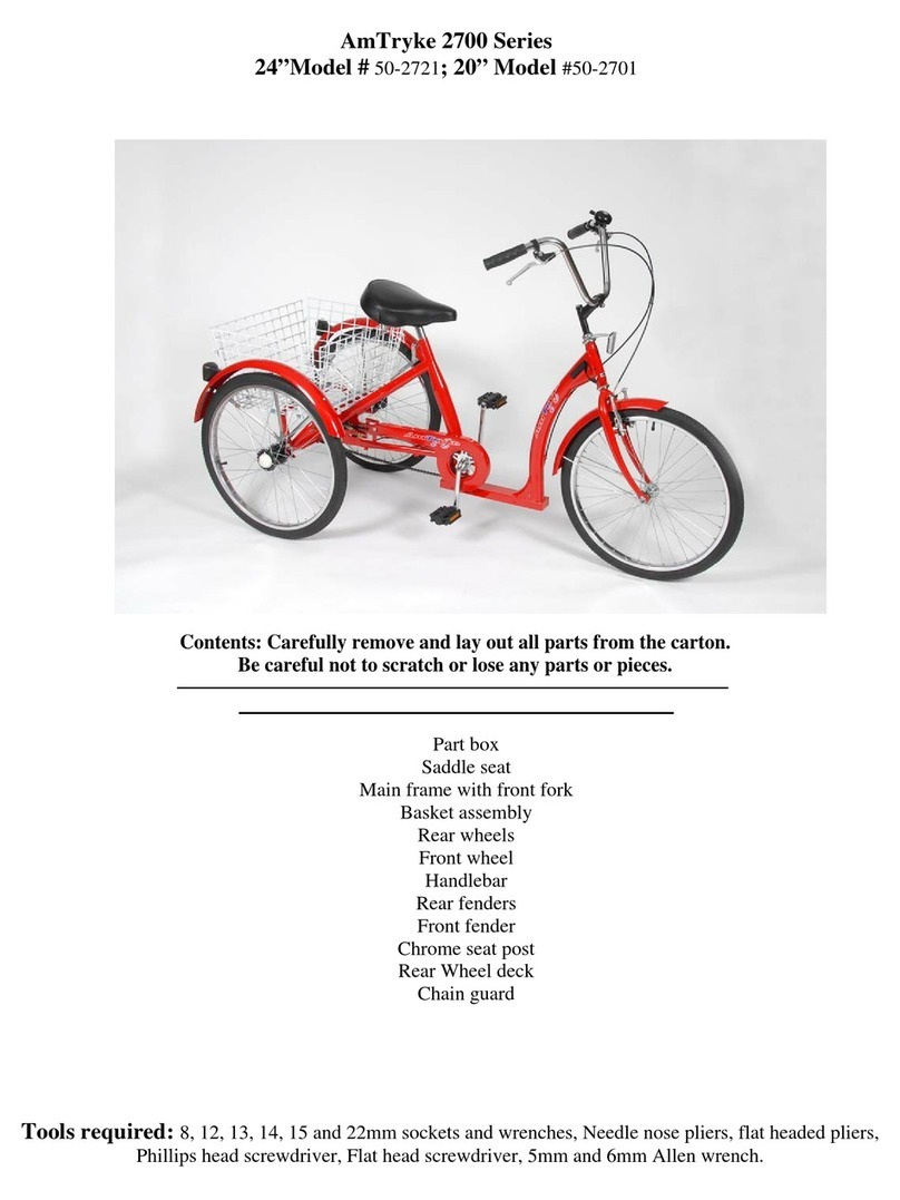
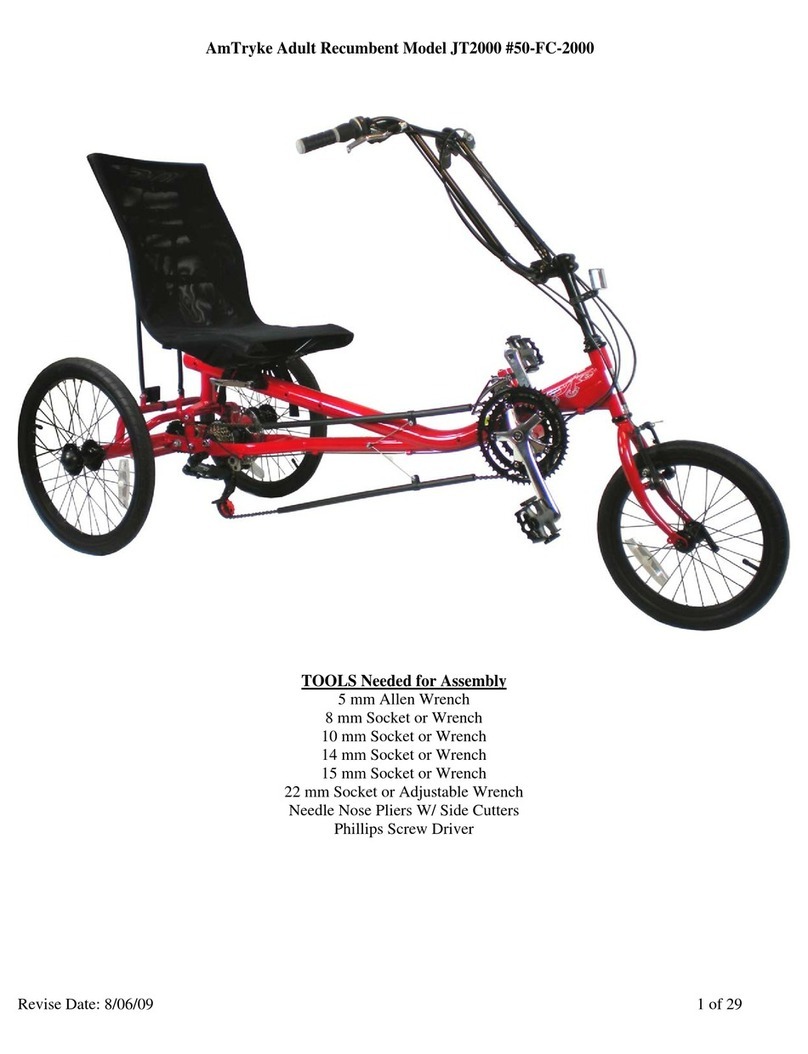
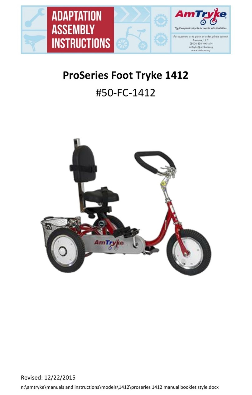
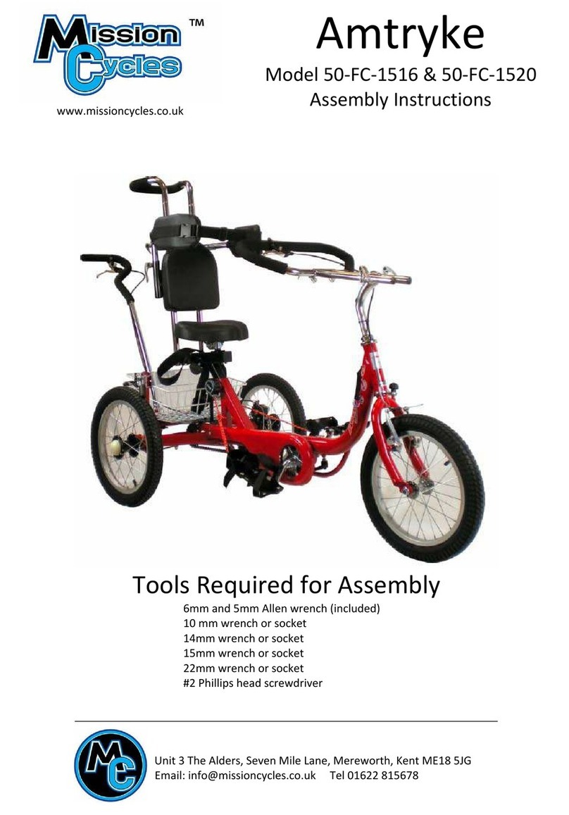
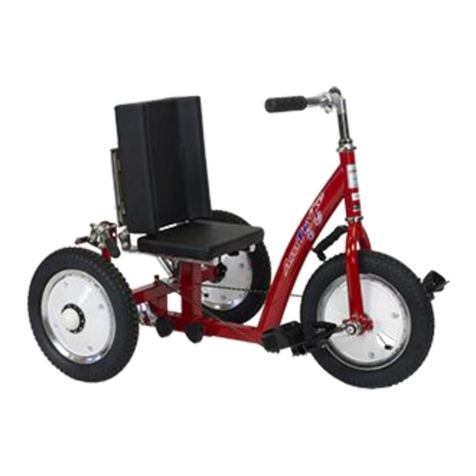
AmTryke 1416 User manual

Instruction
Manual
(Part #s: 50-FC-1416, 50-FC-1420, 50-FC-1420-XL)
Includes Rear Steering Kit Instructions for
1416, 1420, and 1420-XL
(Part #s: 30-50-1516; 30-50-1520; 30-50-1420-XL)
1416,
1420,
1420-XL

Contents
About Amtrykes®.............................................................................................1
About This Manual ..........................................................................................1
Safety..............................................................................................................2
Safe Riding Tips................................................................................................ 2
Brakes.......................................................................................................... 4
Shift Gears................................................................................................... 4
Assembly Instructions .....................................................................................5
Getting Started ................................................................................................ 5
Frames ............................................................................................................. 7
Wheels............................................................................................................. 8
Parking Brake................................................................................................. 17
Handlebar ...................................................................................................... 17
Seat................................................................................................................ 18
Pedals ............................................................................................................ 21
Pedal Leveler Pulley .................................................................................. 22
Basket ............................................................................................................ 22
Steering Pin.................................................................................................... 23
Wheel Reflectors ........................................................................................... 23
Additional Assembly Instructions .................................................................. 25
Front Brake (Models 1416 and 1420) ............................................................ 25
Brake Lever and Cable............................................................................... 25
Brake Caliper ............................................................................................. 26
Brake Adjustment ..................................................................................... 27
3-Speed Model (1416 and 1420) ................................................................... 27
Rear Steering Bar with Hand Brake (Models 1516 and 1520) ....................... 29
Fitting Amtryke for Rider............................................................................... 32
Optional Accessories ..................................................................................... 33
Troubleshooting ............................................................................................ 33
Maintenance .................................................................................................34
Wheels and Tires ........................................................................................... 34
Brakes ............................................................................................................ 34
Chain.............................................................................................................. 34
Maintenance Schedule .................................................................................. 35
Warranty.......................................................................................................36
Useful Information ........................................................................................ 36
Amtryke Therapeutic Tricycle Program ......................................................... 36
Donations ...................................................................................................... 37
Returns and Refunds ..................................................................................... 38
Amtryke Sizing Charts ......................................... Error! Bookmark not defined.
Tools ................................................................... Error! Bookmark not defined.
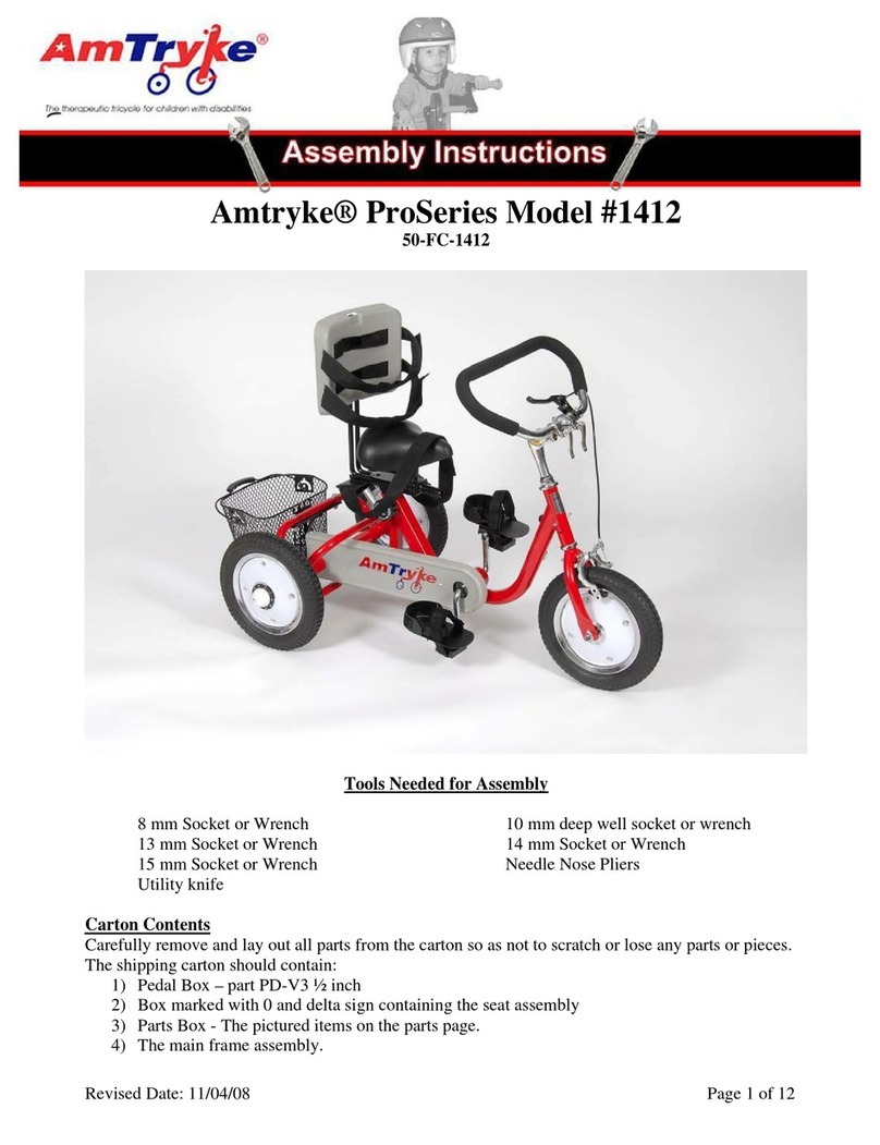
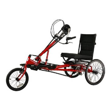
About Amtrykes®
Amtryke, LLC is fully owned and operated by National AMBUCS™ Inc, a 501c3
charity. Amtryke therapeutic tricycles are designed for people with disabilities
who are unable to safely operate a traditional bicycle. Amtryke tricycles or
“trykes,” can be operated by feet, hands or both feet and hands together. A
wide variety of models can be adjusted to fit the needs of different riders by
choosing the optimal seat, handlebars, back rest and adaptive accessories.
ProSeries models 1416,1420, and 1420-XL are fixed drive trykes that provide
full support to riders with low tone or who need additional trunk support.
Some of the features include a sliding seat post bracket, adjustable seat and
seatback (up/down and forward/back) and lateral supports with a chest strap.
The telescoping handlebar allows flexible positioning. The expanding pedals are
also highly adjustable. These trykes also have a loading brake that makes rider
transfer safe and easy and a safety steering limiter pin to prevent over-
steering. Models also feature a front brake, which can be controlled by rider or,
if a Rear Steering Kit is added, by the caregiver.
These trykes can be adapted for high functioning riders. The first high
functioning option requires a switch to the existing freewheel hub and the
addition of a Disk Brake Kit (Required for safety). The second option is for
riders who want gearing to take on hilly terrain and would require the addition
of the 3-speed Gear Kit and a coaster brake. Riders must be able to make a
complete pedal rotation on their own and they must also have the cognitive
ability to steer successfully and apply the coaster brake and/or the hand brake.
All models can be adapted with several accessories including Rear Steering Kits.
See Optional Accessories in this manual for more information. You can also visit
our website for most up to date information at www.ambucs.org.
About This Manual
Read this manual carefully before assembling your tryke or using it for the first
time. This manual includes important information about safety, assembly and
maintenance. Keep this manual in a safe place for information and for ordering
accessories/parts.
AMBUCS/Amtryke reserves the right to make changes to the design and
technology of Amtrykes. The assembly instructions are accurate as of the date
of this manual’s printing.

2
Safety
Safety is very important to us. Amtryke products are designed in accordance
with the latest safety standards and are constantly monitored for quality. We
use information from this quality control to continually improve our products.
We urge all riders to seek the opinion of their health-care provider(s) before
riding their tryke.
Amtrykes should be used for their intended purpose only.
Safe Riding Tips
Before riding, familiarize yourself how the tryke operates —it’s steering,
braking and gear shifts (if applicable). Adjust the seat, handlebars and pedals to
fit the rider. See Fitting Amtryke for Rider in this manual for more information.
Here are some tips about riding safety:
•Amtrykes should be used with close adult supervision.
•Riders must wear helmets. All our trykes include a free safety-rated helmet.
The helmet must fit appropriately. A properly fitting helmet sits on the head
comfortably −a helmet that sits high on the head is too small. Some
movement is acceptable, but a helmet that moves a lot is too large. See the
illustration below for reference:
Correct Way to Wear Helmet
Wear the helmet flat atop your head,
not tilted back at an angle.
Make sure the helmet fits snugly and
doesn’t obstruct your vision. The chin
strap should fit securely and the buckle
stay fastened.
GRAPHIC COURTESY OF BUDDY BIKE LLC
For more information about
finding the correct size helmet,
see Helmet Sizing Chart on page
30.
NOTE: Be careful not to pinch the
skin when fastening helmet buckle.

3
•Riders must wear shoes. If shoes have laces, they must be tied properly.
•Most trykes are equipped with a steering pin and have three steering options
available:
oFull steering: No steering pin. This option allows riders to make sharp turns
and is appropriate for riders who ride at slow speeds or in close quarters.
Close adult supervision is required.
oLimited steering: This option allows riders to turn 20 degrees in either
direction, thus, reducing the risk of over-steering or tipping over.
oNo steering: This option allows for riding straight only. A supervising adult
is required to turn the tryke.
•To avoid tipping the tryke over, approach wheelchair ramps or thresholds at
a 90-degree angle.
•Use caution on sloped parking lots, driveways and sidewalks. Avoid excess
speed by having an adult restrain the tryke from behind on sloped surfaces.
The trykes have many options for control features. Consult Amtryke to find
out the best solution for your rider.
•Many riders do not have the motor skills required to be able to use the hand
brake effectively.
•Depending on trunk stability, behavioral compliance and body awareness,
some riders may need supports (e.g. lateral, head), belts (e.g. lap, shoulder),
abductor strap or other specialized equipment. A physical therapist/health
professional should assist you with any recommendations.
•Riders should only be allowed to ride trykes that are the appropriate size. If
you are uncertain, refer to Amtryke Sizing Chart in this manual or contact a
physical therapist or occupational therapist.
•Before riding, always check that all tires are inflated properly.
•If parts are broken or missing, the tryke should not be used until repaired.
WARNING: DO NOT RIDE IN OR NEAR TRAFFIC, OR WHERE THERE IS
A RISK OF FALLING OFF CURBS, STAIRS, POTHOLES OR OTHER HAZARDS.
WARNING: NEVER ALLOW MORE THAN ONE RIDER ON AMTRYKE.
WARNING: DO NOT RESTRAIN TRYKE BY GRABBING HANDLEBARS
OR HAND BRAKE —THIS MAY CAUSE IT TO TURN SHARPLY AND TIP
OVER.

4
Brakes
If your tryke has brakes (front or coaster brakes) be careful when using the
brakes. Operate the brakes gradually. If your tryke has front brakes (front
caliper brake or both front caliper brake and rear disk brake) squeeze the brake
lever(s) gradually until you feel brake(s) working. The left brake lever operates
the front caliper brake and the right lever operates the rear brake. To stop your
tryke, use both brakes. It is advisable to start braking by operating the rear
brake slightly before the front brake.
Shift Gears
If your tryke has gear shifts, use caution when shifting gears. When shifting
gears, keep pedaling but reduce pedaling pressure. Do not try to change gears
when pedals or wheels are not moving. Also, never change gears while back
pedaling and do not force the gear shifter when changing gears.
WARNING: BE CAREFUL WHEN OPERATING BRAKES. SUDDEN
BRAKING MAY CAUSE TRYKE TO TIP OVER.
CAUTION: USE CAUTION WHEN SHIFTING GEARS.

5
Assembly Instructions
Refer to the following instructions on how to assemble your tryke. Study the
instructions carefully before beginning assembly and follow the sequence
shown in the instructions.
Be careful when assembling your tryke. Make sure that your working area is
free of possible sources of danger, such as tools lying around.
Always dispose of packaging material properly. Do not let children play with
plastic bags.
When assembling your tryke, bolt all parts together loosely at first and check
that they have been put together correctly. Tighten locknuts by hand until
snug, and then use proper tools to tighten nuts completely.
Getting Started
Your Amtryke is shipped in parts. Carefully remove and lay out all parts from
the carton so that you don’t scratch or lose any parts or pieces. Check that you
have all the necessary parts. If any parts are missing, please call us at 800-838-
1845 for assistance.
Remove packaging material and discard. Refer to the following picture to
identify different parts:
NOTE: Amtryke must be assembled by an adult.
CAUTION: CHECK THAT ALL SCREWS HAVE BEEN
SECURELY TIGHTENED BEFORE USING YOUR TRYKE.
WARNING: THERE IS ALWAYS A DANGER OF INJURY
WHEN WORKING WITH TOOLS OR DOING MANUAL WORK.
WARNING: THERE IS A RISK OF SUFFOCATION WITH
PLASTIC BAGS. KEEP PLASTIC BAGS AWAY FROM CHILDREN.

6
Your tryke also includes the following hardware/small parts:
Hardware
1416, 1420, 1516 & 1520 parts
Main
frame
Pedal
Back wheel
Front
wheel
Front
brake
Chain
guard
Rear steering control
arm knob (1516, 1520)
Back wheel
Rear steering
bar w. hand
brake (1516,
1520)
Basket
Saddle
seat
Seat back
Seat belt
Lateral supports
Handlebar stem
Rear frame
Seat post
bracket
Handlebar
Parking
brake
Front brake
(1416, 1420)
Lateral T-bar
Pedal leveler
pulley
Seat
securing
knob
Steering pin
holes
Rear steering control
arm (1516, 1520)
Pedal
Frame
knob
Knobs (3)
Steering pin
Brake
noodle
(1416,
1420
Basket
screws (2)
Brake
cable
boot
(1416
,
1420)
Safety
pin
Nut
cover
Front fork tube
Front
fork
Securing
knob
Quick
release
levers
Quick
release
lever
Pedal
crank
Seat post

7
You need the following tools for assembly (too see a picture different tools, see
page 31):
Frames
Start assembling your Amtryke by first attaching the main and rear frames
together:
Step 1: Slide the main frame onto the
rear frame.
Step 2: Insert the safety pin through both
sections.
Step 3: Install the frame knob by turning
it clockwise ½ a turn at a time. Picture
shot above the underside of tryke.
NOTE: The frame knob is spring-
loaded. Once it is threaded into the
frame, pull the knob out to rotate it
backward without loosening it. You
can then tighten it further.
TOOLS REQUIRED:
•5 and 6 mm Allen wrench (incl.)
•10 mm wrench/socket
•14 and 15 mm wrench (incl.)
•22 mm socket or adjustable wrench
•Quick release wrench (incl.)
•#2 Phillips head screwdriver

8
Rear Steering 1500 Kit - optional
Available on ProSeries 1416, 1420, and 1420-XL Amtrykes
(Part #: 30-50-1516; 30-50-1520; 30-50-1420-XL)
1. Install Rear Disc Brake Rotor and Disc Caliper on the left rear wheel axle of
the main frame. The left side is determined from the perspective of riding
the tryke.
a.) Turn axle until the oblong oval slot in the axle faces upwards
b.) IMPORTANT: Insert 15mm Key Way into the slot in the axle
c.) Slide on the disc brake rotor (with screw opening on the hub to the
outside) until it is flush with rear frame. There is a notch in the rotor
that will allow it to slide over the Key Way until it is no longer visible.
Please skip this section if not installing rear steering option

9
2. Install the 3mm set screw through rotor using a 3mm Allen wrench, tighten
securely.
3. Install rear wheels (do not use the 22mm silver spacer tube on the left side
axle if you are installing the rear steering kit).
4. Install front wheel (see assembly manual).
5. Install Disc Brake Caliper.

10
a.) TIP: Flip the bike upside down. It is easier to install the disc brake
caliper and steering control arm support plate from the bottom.
b.) Insure brake pads slide smoothly over brake rotor or disk.
c.) Put in black bolts with 5mm Allen wrench. Hint: tighten the shorter
rear bolt first as it will touch the bracket. Then tighten the front bolt
until the brake is secure. Be sure both sides of the brake bracket
contacts the red rear axle tube evenly.
d.) Test the rear axle rotation. It should spin easily without binding.
6. Install Chrome Steering Control Arm Support.
a.) Use two (2) of the 15mm hex screws provided in the parts bag to
install the chrome support plate in the center of the rear tryke frame.
The groove in the plate should be on the left side of the tryke when
upright.
b.) While you have the tryke upside down. Loosen the two (2) screws
holding the black basket plate on the main frame. Do not remove—
just loosen! This will help in installing other parts.

11
7. Install Red Rear Steering Assembly.
a.) Loosen the two (2) screws holding the black basket plate to the bottom
rear of the main frame first. Just loosen, do not remove.
b.) It is important that all the screws and bolts be loosely installed at first.
This will allow you to line up all the holes and get the screws started
easily. The final step is to tighten all bolts and screws.
c.) Flip tryke right side up.
d.) Remove silver basket bracket, 25mm screws and washers from the
black basket plate and save them for later.
e.) Flip tryke upside down again.
f.) Slide on red rear steering bracket until the holes line up. The silver push
bar brackets should be below and the black steering linkage should be
on top (when tryke is upside down) for easy installation. The bottom

12
side (with tryke upside down) of the red bracket must rest between
tryke frame and black basket plate.
g.) Install two (2) of the 15mm hex head screws but do not tighten yet.
h.) Flip tryke over so it is now right side up.
i.) Now you can install the basket and the red rear steering assembly. The
red bracket goes on top of the rear frame holes and underneath the
black basket plate.
j.) Position the basket and loosely install the Phillips head screw in the
rear center hole. Do not tighten yet.
k.) Place two (2) washers over the bracket holes.
l.) Lay the silver basket bracket over the basket and center over the two
sets of washers. Re-install the 25mm hex head screws and one washer
through the silver bars. Get all bolts and screws started by hand first.
Once all are correctly installed; and started, you can tighten the whole
assembly.
8. Install Steering Control Arm
a.) If your control arm is two-pieced, connect the two red steering control
arm sections by using the two small Allen bolts followed by locknuts as
seen in picture below.

13
b.) Screw red steering control arm into the bushing on the black steering
linkage at rear of tryke and tighten all the way. Then, unscrew it one
rotation to allow adjustments.
c.) Note: This is the straight end. The curved end of the red linkage bar
goes at the front and attaches to the front fork.

14
d.) Important Step: Attach the red steering control arm to the silver
steering control arm support plate. The Allen screw is already installed
on the steering control arm support plate inside a plastic bushing. Use
the 5mm Allen wrench to fully tighten into the steering control arm.
e.) Flip tryke right side up.
f.) Remove black plastic cap from tab/stud/shaft on the left upper fork and
discard.
g.) Slide steering rod bushing over tab/stud/shaft at top front of the fork.
h.) Install and tighten black plastic T-knob to secure.

15
9. Install Rear Steering Bar
a.) Note: Very important—the steering bar must be inserted fully into the
cinch collar—the minimum insertion lines must be down inside the
collar. If not installed correctly, you risk breaking the steering bar.
b.) Once the steering bar is fully inserted—align with front wheel for
straight ahead position—then tighten the two 5mm Allen screws on
the cinch collar.
Wheels
Before you begin to install the wheels, inflate the tires to proper pressure −35
psi. Start with the back wheels, make sure tire tread direction indicated on
sidewall:

16
Follow these steps to install the front wheel:
d.) Loosen nuts on both sides of the
wheel axle and slide the front fork
onto the axle.
e.) Tighten nuts and washers securely
using a 15 mm wrench or socket.
Step 3: Place a cover onto the axle nut.
Press firmly and lightly tap with the palm
of your hand.
CAUTION: DO NOT OVER TIGHTEN
NUTS; BEARINGS WILL BE DAMAGED.
Spin wheels, if there is drag, loosen
wheel nut ¼ turn.
NOTE: Safety washers go on the
outside of fork. The serrated tooth
side of the washer installs against
the red fork blade.
Step 1: Remove nuts and washers from
both sides of the rear axle and slide back
wheels onto the axle.
Step 2: Replace washers and nuts on both
sides. Use a 22 mm socket or adjustable
wrench to tighten.
Nut
Safety
washer
NOTE: Make sure the wheel is centered between the blades of the fork
while securing.
Front wheel

17
Parking Brake
Parking brake is used to help transition rider on/off
the tryke safely and easily. To install it:
1. Remove the two Allen bolts from the brake’s
extension tube.
2. Place the extension tube over the right rear axle
so that the handle is pointing toward the front of
tryke.
3. Install the two Allen bolts up through the
attached fender bracket on the axle and turn
them clockwise into the extension tube.
4. Tighten the two Allen head screws from the bottom.
Handlebar
Handlebar is installed by first placing the handlebar stem into the front fork
steering tube.
Parking brake (picture from
rear of tryke)
NOTE: The tube angles slightly outward to position the brake over the
tire. Be sure the foot of the bracket is fully on top of the red axle tube.
WARNING: DO NOT USE PARKING BRAKE FOR
BRAKING. DOING SO MAY CAUSE SERIOUS INJURY.
NOTE: Make sure the handle is in
the down position and over the tire.
CAUTION: PAY CLOSE ATTENTION TO MAXIMUM HEIGHT LINE. HASH
MARKS SHOULD BE COMPLETELY INSIDE FRONT FORK TUBE.
Allen
bolt

18
When the stem is securely tightened, remove the two 6 mm Allen bolts from
the handlebar clamp (see image below). Insert the handlebar with the quick
release levers oriented up and replace the handlebar clamp. Tighten the bolts.
Seat
Seat assembly consists of a seat post bracket, saddle seat and seat post. Start
by installing the red seat post bracket onto the rear frame:
Front fork tube
Handlebar stem
DO NOT EXCEED THE MAX. HEIGHT LINE
Handlebar clamp
Handlebar stem
Allen bolts
Handlebar
clamp
Handlebar
clamp
Quick
release
lever
Hash
marks
TIP: Use the quick release wrench to
easily tighten quick release levers.
This manual suits for next models
5
Table of contents
Other AmTryke Bicycle manuals

AmTryke
AmTryke 50-FC-1416 User manual

AmTryke
AmTryke Pro Series User manual

AmTryke
AmTryke 1020 User manual

AmTryke
AmTryke 2700 Series User manual

AmTryke
AmTryke HP1000 User manual

AmTryke
AmTryke 1412 User manual

AmTryke
AmTryke 50-FC-1516 User manual

AmTryke
AmTryke AM-12S User manual

AmTryke
AmTryke AM Series User manual

AmTryke
AmTryke JT-2300-USS User manual