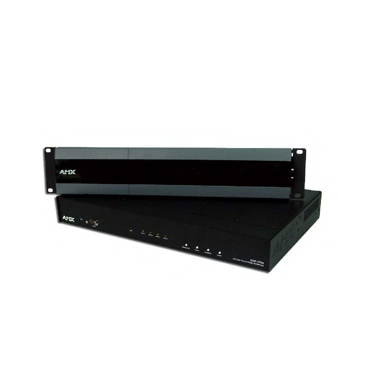
AMX AXB-TPI/3 User manual

instruction manual
To u c h Pa n e l s a n d A c c e s s o r i e s
AXB-TPI/3
Touch Panel Interface 3
(Firmware version G3)

AMX Limited Warranty and Disclaimer
AMX Corporation warrants its products to be free of defects in material and workmanship under normal use for three
(3) years from the date of purchase from AMX Corporation, with the following exceptions:
• Electroluminescent and LCD Control Panels are warranted for three (3) years, except for the display and touch
overlay components that are warranted for a period of one (1) year.
• Disk drive mechanisms, pan/tilt heads, power supplies, and MX Series products are warranted for a period of one
(1) year.
• AMX Lighting products are guaranteed to switch on and off any load that is properly connected to our lighting
products, as long as the AMX Lighting products are under warranty. AMX Corporation does guarantee the
control of dimmable loads that are properly connected to our lighting products. The dimming performance or
quality cannot be guaranteed due to the random combinations of dimmers, lamps and ballasts or transformers.
• Unless otherwise specified, OEM and custom products are warranted for a period of one (1) year.
• AMX Software is warranted for a period of ninety (90) days.
• Batteries and incandescent lamps are not covered under the warranty.
This warranty extends only to products purchased directly from AMX Corporation or an Authorized AMX Dealer.
All products returned to AMX require a Return Material Authorization (RMA) number. The RMA number is
obtained from the AMX RMA Department. The RMA number must be clearly marked on the outside of each box.
The RMA is valid for a 30-day period. After the 30-day period the RMA will be cancelled. Any shipments received
not consistent with the RMA, or after the RMA is cancelled, will be refused. AMX is not responsible for products
returned without a valid RMA number.
AMX Corporation is not liable for any damages caused by its products or for the failure of its products to perform.
This includes any lost profits, lost savings, incidental damages, or consequential damages. AMX Corporation is not
liable for any claim made by a third party or by an AMX Dealer for a third party.
This limitation of liability applies whether damages are sought, or a claim is made, under this warranty or as a tort
claim (including negligence and strict product liability), a contract claim, or any other claim. This limitation of
liability cannot be waived or amended by any person. This limitation of liability will be effective even if AMX Corpo-
ration or an authorized representative of AMX Corporation has been advised of the possibility of any such damages.
This limitation of liability, however, will not apply to claims for personal injury.
Some states do not allow a limitation of how long an implied warranty last. Some states do not allow the limitation or
exclusion of incidental or consequential damages for consumer products. In such states, the limitation or exclusion of
the Limited Warranty may not apply. This Limited Warranty gives the owner specific legal rights. The owner may
also have other rights that vary from state to state. The owner is advised to consult applicable state laws for full
determination of rights.
EXCEPT AS EXPRESSLY SET FORTH IN THIS WARRANTY, AMX CORPORATION MAKES NO
OTHER WARRANTIES, EXPRESSED OR IMPLIED, INCLUDING ANY IMPLIED WARRANTIES OF
MERCHANTABILITY OR FITNESS FOR A PARTICULAR PURPOSE. AMX CORPORATION
EXPRESSLY DISCLAIMS ALL WARRANTIES NOT STATED IN THIS LIMITED WARRANTY. ANY
IMPLIED WARRANTIES THAT MAY BE IMPOSED BY LAW ARE LIMITED TO THE TERMS OF THIS
LIMITED WARRANTY.

Table of Contents
i
AXB-TPI/3 Touch Panel Interface 3
Table of Contents
Product Information .................................................................................................1
Specifications .................................................................................................................... 2
Installation .................................................................................................................5
Installing the Input Modules............................................................................................... 5
Removing Input Modules................................................................................................... 5
Mounting the TPI/3 in an Equipment Rack........................................................................ 6
Other Mounting Options .................................................................................................... 7
Wiring the AXB-TPI/3 ........................................................................................................ 7
Wiring guidelines...................................................................................................................... 7
Preparing captive wires............................................................................................................ 8
Using the AXlink connector for data and power ....................................................................... 8
Using the (DB-9) RS-232 connector for mouse control or data ............................................... 9
Using the VGA IN DB-15 (male) high-density connector ......................................................... 9
TPI Configuration and Usage ................................................................................11
Setting Up Serial Communication from PC to the TPI/3.................................................. 11
Setting Up serial procedures.................................................................................................. 11
Using AXCESSX for serial communication ............................................................................ 11
Using HyperTerminal for serial communication ..................................................................... 13
Setting up Touch Devices and Drivers ............................................................................ 14
Setting the Output Resolution ................................................................................................ 14
Assigning a touch device ....................................................................................................... 15
Calibrating the Monitor ........................................................................................................... 16
Verifying your settings............................................................................................................ 16
Setting Up AXlink Communication from Master to the TPI/3........................................... 17
Setting Up AXlink procedures ................................................................................................ 17
Using AXCESSX for AXlink communication .......................................................................... 17
Using HyperTerminal for AXlink communication.................................................................... 17
Setting up the touch device through AXlink ........................................................................... 18
Setting Up NetLinx Communication from PC to the TPI/3............................................... 19
Using NetLinx Studio for communication via an Ethernet connection.................................... 19
Using NetLinx Studio for communication via an COM Port.................................................... 20
Stacking the TPI/3 ........................................................................................................... 21
Using a CG10 LCD Touch Panel with the AXB-TPI/3 ..................................................... 24

ii AXB-TPI/3 Touch Panel Interface 3
Table of Contents
Designing Touch Panel Pages ..............................................................................27
Buttons ............................................................................................................................ 27
Activating Edit Mode ....................................................................................................... 28
Setting the Device Base.................................................................................................. 30
Setting the Device Used.................................................................................................. 30
Adding a Page................................................................................................................. 30
Setting the page color ............................................................................................................ 30
Adding a Button............................................................................................................... 30
Resizing a button ................................................................................................................... 30
Defining On-Screen and External Button Properties....................................................... 31
Setting the channel code........................................................................................................ 31
Setting the variable text code................................................................................................. 32
Setting the page flip ............................................................................................................... 32
Setting the button colors for channel-off conditions ............................................................... 32
Adding text, icons, and bitmaps to a button ........................................................................... 32
Using TPDesign3 to Download Bitmaps, Icons, and Fonts............................................. 33
Creating a Bargraph and Joystick................................................................................... 33
Adding a bargraph or joystick button...................................................................................... 34
Setting Bargraph and Joystick Properties....................................................................... 34
Setting the level code............................................................................................................. 34
Programming ..........................................................................................................35
Serial Commands............................................................................................................ 35
System Send_Commands .............................................................................................. 39
Video Send_Commands ................................................................................................. 46
VGA Send_Commands................................................................................................... 48
Programming Numbers ................................................................................................... 50
Shorthand Send_Commands.......................................................................................... 51
Color Send_Commands.................................................................................................. 57
Variable Text Send_Commands ..................................................................................... 59
Shorthand Variable Text Commands .............................................................................. 61
Button String Commands ................................................................................................ 64
Upgrading the Firmware ........................................................................................67
Upgrading the Firmware Using NetLinx Studio ............................................................... 67
Upgrading the TPI/3 Firmware through a COM port .............................................................. 67
Upgrading the TPI/3 Firmware through an IP Address ................................................... 69
Upgrading the Firmware Using SoftROM........................................................................ 72
Configuration.......................................................................................................................... 72
Downloading the Firmware .................................................................................................... 72

Table of Contents
iii
AXB-TPI/3 Touch Panel Interface 3
Replacing the Batteries ..........................................................................................75
Troubleshooting .....................................................................................................77
Appendix .................................................................................................................79

iv AXB-TPI/3 Touch Panel Interface 3
Table of Contents

Product Information
1
AXB-TPI/3 Touch Panel Interface 3
Product Information
The AXB-TPI/3 (FIG. 1) is a touch panel interface capable of using multiple (RGB and consumer-
type) inputs and of displaying its graphical user interface (GUI) output on practically any type of
monitor. The look and feel of the GUI is similar to the AXT-CG10 touch panel firmware. The
AXB-TPI/3 has three slots on the rear panel that can contain any combination of three types of
input modules: composite video/S-video (TP3-VID), RGB (TP3-RGB), and VGA (TP3-VGA).
The touch input works via a serial device, such as a serial mouse or touch monitor. The output can
be displayed on any VGA device that accepts a standard VGA HD-15 connector, or RGB device
that accepts a 5-BNC (red, green, blue, horizontal sync, and vertical sync) connector.
The AXB-TPI/3 (TPI) acts as an AXlink-controlled video switcher. It can be used in multimedia
applications requiring showing multiple video sources on an RGB projector. Depending on which
input modules you use, the TPI/3 can accept up to six inputs (with three TP3-VID input modules).
Since the TPI/3 accepts any combination of input modules, it can be stacked, allowing an unlimited
number of video sources; refer to the Stacking the TPI/3 section on page 21 for more information.
FIG. 1 AXB-TPI/3 (front and rear views)
12VDC
SLOT 2 SLOT 1
TP3-VID
COMP Y/C
TP3-VGA
VGA R
TP3-RGB
AXlink
GND
AXP
AXM
PWRMOUSE PORT
SLOT 3
PWR
MONITOR
OUT
R G HB V
GH/HVB V
Slot 3
(shown with
TP3-VGA module)
Slot 2
(shown with
TP3-RGB module)
Slot 1
(shown with
TP3-VID module)
Mouse port
Monitor Out
(VGA-HD15)
Monitor Out
(5 BNC) controlling
RGBHV
12 VDC
power connector
AXlink
connector
VGA SVGA AXlinkXGA
PORT
PROGRAM
Rack-mounting brackets
VGA output LED
SVGA output LED
XGA output LED
AXlink LED
DB-9 Program Port
Front View
Rear View

Product Information
2AXB-TPI/3 Touch Panel Interface 3
Specifications
The following table lists the specifications for the AXB-TPI/3 and its related input modules.
Specifications
Dimensions (HWD): 3.47" x 13.75" x 8.38" (8.81 cm x 34.93 cm x 21.29 cm)
• With brackets installed for rack-mounting: 3.47" x 19.00" x 8.38"
(8.81 cm x 48.26 cm x 21.29 cm)
• With brackets rotated 45° for under/over/vertical surface mounting:
3.85" x 19.00" x 8.38" (9.78 cm x 48.2 cm x 21.29 cm)
Weight: 4.85 lbs (2.20 kg)
Power Requirements: • 630 mA - with no input modules (cards) only supplying power to the TPI/3
• 1.13 A - with 1 input module/card - 500 mA input module
• 1.63 A - with 2 input modules/card - 500 mA input module
• 2.13 A - with 3 input modules/card - 500 mA input module
Input Voltage: 12 VDC
Front Panel:
Output Resolution LEDs 3 red LEDs indicate the output video resolution:
• VGA LED - VGA output display resolution LED lights to indicate an active 640
x 480 (HV) resolution.
• SVGA LED - SVGA output display resolution LED lights to indicate an active
800 x 600 (HV) resolution.
• XGA LED - XGA output display resolution LED lights to indicate an active
1024 x 768 (HV) resolution.
AXlink LED Green LED indicates AXlink status. AXlink LED blinks to indicate the communi-
cation activity, power, and data status:
• One blink per second: Power is active and AXlink data communication is
functional.
• Full On: Power is active and AXlink data communication is not functional.
Program Port 4-pin AXlink data/power bus jack. This port is an RS-232 DB-9 connector
(male) that can be connected to a DB-9 port on a PC; used with serial com-
mands, SoftROM downloads, other DB-9 capable panels, and to upload/down-
load touch panel page information from the TPDesign3 program.
Touch Drivers Downloadable touch drivers allow you to add to the standard list of available
drivers. Currently supports devices such as the Elo Intellitouch®touch monitor.
• Refer to the Appendix section on page 79 for a listing of touch panel drivers
that have been tested with the TPI/3.
Memory: Standard 9 MB (8 MB flash)
Font Support: Unicode font support. Buttons with Unicode fonts can only be created and
edited with the TPDesign3 Touch Panel Program (Version 3.13 or higher).
Slots: Equipped with any combination of input modules (S-Video/Composite, VGA,
and RGB).
Outputs: VGA, HD-15, and RGB 5-BNC

Product Information
3
AXB-TPI/3 Touch Panel Interface 3
Specifications (Cont.)
Rear Panel Components:
TP3-VID Use the TP3-VID input module in any input slot to connect video sources, such
as VCRs and DVDs. The module is secured by two black thumbscrews.
• 500 mA power consumption
• Composite LED indicator (turns on when composite video input is detected).
The Composite video input types are: NTSC, SECAM, or PAL.
• Composite input connector
• S-Video LED indicator (turns on when S-Video input is detected).
• S-Video input connector
TP3-RGB Use the TP3-RGB input module in any input slot to connect RGB-type sources.
The module is secured by two black thumbscrews.
• 5-BNC input connectors: R (Red), G (Green), B (Blue), H/HV (Horizontal/
Composite sync), V (Vertical sync)
• 500 mA power consumption
The TP3-RGB input module accepts the following configurations:
• Red, green, blue, horizontal sync, vertical sync
• Red, green, blue, composite sync (on H/HV connector)
• Red, green, blue, with sync on green signal
To achieve the best video quality on the VGA and RGB modules, use an alter-
nating pixel pattern to fine tune the picture.
TP3-VGA Use the TP3-VGA input module in any input slot to connect VGA-type sources
(common for PCs). The module is secured by two black thumbscrews.
• One HD-15 input connector
• 500 mA power consumption
The TP3-VGA input module accepts the following configurations:
• Red, green, blue, horizontal sync, vertical sync
• Red, green, blue, composite sync
• Red, green, blue, with sync on green signal
Mouse Port RS-232 (DB-9) 9-pin serial port. The 9-pin serial port is used to connect a
pointer device, such as a serial mouse. The AXB-TPI/3 also supports several
external serial touch devices such as some touch pads, touch-sensitive moni-
tors, and tablets. Refer to FIG. 6 on page 9 for more information.
Monitor Out (VGA) HD-15 VGA output connector. The AXB-TPI/3 contains two types of GUI output
connectors: DB15 and 5-BNC RGB output connectors. VGA connection is
done through the use of the VGA (HD-15) monitor output for VGA-type moni-
tors (common to PCs). Connect the VGA output monitor's HD-15 (female) con-
nector to the VGA connector (male) on the rear panel of the AXB-TPI/3.
Monitor Out (RGB) RGB connection is done by using the five BNC output connectors (from left to
right) red (R), green (G), blue (B), horizontal sync (H), and vertical sync (V).
Connect the RGB output monitor's 5-BNC connectors to the RGB connectors
on the rear panel of the AXB-TPI/3. Refer to the Using the VGA IN DB-15
(male) high-density connector section on page 9 for more information.
• RGB (5-BNC) output connectors
• Red, Green, Blue, Horizontal Sync, Vertical Sync
AXlink Connector 4-pin AXlink data/power bus jack
Power 2-pin 12 VDC power supply jack
Output Refresh Rates per
Resolution
• 640 x 480 (VGA): 60 Hz, 72 Hz, 75 Hz, 85 Hz
• 800 x 600 (SVGA): 56 Hz, 60 Hz, 72 Hz, 75 Hz
• 1024 x 768 (XGA): 60 Hz
Enclosure Metal with black matte finish
Product Information
4AXB-TPI/3 Touch Panel Interface 3
Specifications (Cont.)
Input resolution and refresh
rates per resolution (RGB
and VGA only)
• 640 x 480 (VGA): 60 Hz, 72 Hz, 75 Hz, 85 Hz
• 800 x 600 (SVGA): 56 Hz, 60 Hz, 72 Hz, 75 Hz
• 1024 x 768 (XGA): 60 Hz, 70 Hz, 75 Hz, 85 Hz
TPI/3 Programming • Serial connection: Connect a DB-9 cable from your PCCOM port to the
Program port located on the front of the AXB-TPI/3. This is the only method
of programming the TPI/3 using Serial Commands.
•AXlink connection: Connect a DB-9 cable from your PCCOM port to the
Programming port on the Controller. Then use an AXlink cable to connect the
AXlink connector on the Controller to the AXlink connector at the rear of the
AXB-TPI/3. This is the only method of programming the interface unit using
Send_Commands.
Included Accessories • Two rack-mount ears and a package of rack screws
• One 4-pin AXlink connector
• One 2-pin PWR connector
Optional • PS2.8 Power Supply with 3.5 mm mini-Phoenix connector (FG423-11)
• Input module (TP3-VID, TP3-RGB, and TP3-VGA)
The input slots are universal. You can use any combination of input modules in any of
the three input slots. The AXB-TPI/3 handles multiple input resolutions and refresh
rates.

Installation
5
AXB-TPI/3 Touch Panel Interface 3
Installation
The mounting brackets can be rotated 90° in any direction to accommodate several different
mounting options, including standard 19" (48.26 cm) equipment rack mounting, tabletop, under/
over the table, and vertical wall mounting.
Installing the Input Modules
1. Disconnect the power supply from the TPI/3.
2. Discharge the static electricity from your body by touching a grounded metal object.
3. Disconnect all connectors from the AXB-TPI/3.
4. Gently insert the module into the brackets inside the card slot and slide the input module into
the enclosure until you feel it contact the slot connector, as shown in FIG. 2.
5. Screw in (clockwise) the two thumbscrews to secure the each module.
6. Repeat steps 4 and 5 to insert other input modules, if necessary.
7. When you are done installing the input modules, reconnect all connectors, and apply power.
Removing Input Modules
1. Disconnect the power supply from the TPI/3.
2. Discharge the static electricity from your body by touching a grounded metal object.
3. Disconnect all connectors from the TPI/3 input module.
4. Remove (counter-clockwise) the two black thumbscrews on the input module.
5. Slide the module out of the enclosure.
Always power down the TPI/3 before attempting to remove or install input modules.
Failure to do so could result in damage to the TPI/3 and/or input modules.
FIG. 2 Inserting an input module
Always power down the TPI/3 before attempting to remove or install input modules.
Failure to do so could result in damage to the TPI/3 and/or input modules.

Installation
6AXB-TPI/3 Touch Panel Interface 3
6. Repeat steps 4 and 5 for other slots, as required.
7. Ensure that all thumbscrews are secured, reconnect all rear panel connectors, and apply power.
Mounting the TPI/3 in an Equipment Rack
Use the supplied mounting brackets for 19" equipment rack installations. Remove the mounting
brackets for flat surface installations. You will need a Phillips screwdriver to install the TPI/3.
To install the AXB-TPI/3 in an equipment rack:
1. Discharge the static electricity from your body by touching a grounded metal object.
2. Install the mounting brackets using the screws supplied with the unit, as shown in FIG. 3.
3. With the rack mount brackets installed, place the AXB-TPI/3 into the equipment rack, and
align the mounting bracket holes with the mounting holes on the equipment rack. Start the
mounting screws on both sides of the controller and tighten.
4. Thread the incoming AXlink, power cable (optional), touch device (serial mouse or other), and
video/graphic input and output cables through the opening in the equipment rack. The
maximum length for the mouse cable is 25 feet (7.62 meters).
5. Disconnect the AXlink connector from the Controller, the RS-232, and optional video/graphic
wiring from the source equipment.
6. Connect the AXlink, power, and video/graphic wiring to the AXB-TPI/3. Refer to the Wiring
the AXB-TPI/3 section on page 7 for wiring diagrams and pinout descriptions.
7. Connect the AXlink wiring to the Controller, RS-232, and optional video/graphic wiring to the
source equipment. The AXB-TPI/3 beeps when you apply power and again when AXlink
communication is detected.
FIG. 3 Installing mounting brackets

Installation
7
AXB-TPI/3 Touch Panel Interface 3
Other Mounting Options
Rotate the mounting brackets to mount the AXB-TPI/3 on top of a flat surface, under a flat surface,
or vertically. The following steps apply to all of these mounting options.
1. Discharge the static electricity from your body by touching a grounded object.
2. Position and install the mounting brackets, as shown in FIG. 4, using the screws supplied with
the unit. The mounting brackets can be rotated to accommodate your mounting needs.
3. Disconnect the AXlink connector from the Controller, the RS-232, and optional video/graphic
wiring from the source equipment.
4. Connect the AXlink, power, and video/graphic wiring to the AXB-TPI/3. Refer to the Wiring
the AXB-TPI/3 section below for wiring diagrams and pinout descriptions.
5. Connect the AXlink wiring to the Controller, RS-232, and optional video/graphic wiring to the
source equipment. The AXB-TPI/3 beeps when you apply power, and again when AXlink
communication is detected.
Wiring the AXB-TPI/3
The AXB-TPI/3 uses a 4-pin AXlink connector for power and data. If the distance between the
AXB-TPI/3 and the Controller exceeds power consumption limits, you must connect an optional
12 VDC power supply to the 2-pin PWR connector.
Wiring guidelines
The AXB-TPI/3 requires 12 VDC power to operate properly. An auxiliary 12 VDC power supply
provides power to the TPI/3. Each module adds 500 mA of current consumption (in addition to the
baseline 630 mA on the TPI/3 system. The unit should only have one source of incoming power.
FIG. 4 Mounting TPI/3 on a flat surface
Do not connect power to the TPI/3 until wiring is complete. If you are using a 12 VDC
power supply, apply power to the TPI/3 only after installation is complete.
Wiring Guidelines - No Module Wiring Guidelines - One Module
Wire size Maximum wiring length Wire size Maximum wiring length
18 AWG 186.30 feet (56.78 meters) 18 AWG 103.87 feet (31.66 meters)
20 AWG 117.87 feet (35.93 meters) 20 AWG 65.72 feet (20.03 meters)
22 AWG 73.49 feet (22.40 meters) 22 AWG 40.97 feet (12.49 meters)
24 AWG 46.32 feet (14.12 meters) 24 AWG 25.83 feet (7.87 meters)

Installation
8AXB-TPI/3 Touch Panel Interface 3
Preparing captive wires
You will need a wire stripper and flat-blade screwdriver to prepare and connect the captive wires.
1. Strip 0.25 inch (6.35 mm) of insulation off all wires.
2. Insert each wire into the appropriate opening on the connector, according to the wiring
diagrams and connector types described in this section.
3. Tighten the screws to secure the wire in the connector. Do not tighten the screws excessively;
doing so may strip the threads and damage the connector.
Using the AXlink connector for data and power
To use the AXlink 4-pin connector for data communication with the Central Controller and power
transfer from the PSN6.5 power supply, the incoming PWR and GND cable from the PSN6.5 must
be connected to the AXlink cable connector going to the Central Controller. FIG. 5 shows the
AXlink wiring diagram. Always use a local power supply to power the TPI/3 unit.
1. Unscrew the PWR and GND wires on the terminal end of the PSN6.5 2-pin cable.
Wiring Guidelines - Two Modules Wiring Guidelines - Three Modules
Wire size Maximum wiring length Wire size Maximum wiring length
18 AWG 72.01 feet (21.95 meters) 18 AWG 55.10 feet (16.79 meters)
20 AWG 45.56 feet (13.89 meters) 20 AWG 34.86 feet (10.63 meters)
22 AWG 28.40 feet (8.66 meters) 22 AWG 21.74 feet (6.63 meters)
24 AWG 17.90 feet (5.46 meters) 24 AWG 13.70 feet (4.18 meters)
Using more than one source of power to the AXB-TPI/3 can result in damage to the
internal components and a possible burn out.
Never pre-tin wires for compression-type connections.
FIG. 5 AXlink connector wiring diagram
PWR (+)
GND (-)
Local +12 VDC power supply
(coming from the PSN power supply)
PWR +
AXP/TX
AXM/RX
GND -
PWR +
AXP/TX
AXM/RX
GND -
To the Central Controller To the AXB-TPI/3
Do not connect the wire from the PWR terminal on the Central Controller to the PWR
terminal on the TPI/3 unit when you connect an external power supply. Make sure to
connect only the AXM, AXP, and GND wires on the TPI/3’s AXlink connector when
using the PSN6.5 power supply.

Installation
9
AXB-TPI/3 Touch Panel Interface 3
2. Pair the GND wires from the PSN6.5 and the Central Controller AXlink connectors together
and insert them into the clamp position for GND on the TPI/3’s AXlink connector.
3. Tighten the clamp to secure the two GND wires.
4. Place the PWR wire from the PSN6.5 into the open clamp position for PWR on the TPI/3’s
AXlink connector.
5. Tighten the clamp to secure the PWR wire.
Using the (DB-9) RS-232 connector for mouse control or data
The dual-function (DB-9) RS-232 connector supports most standard serial mouse control devices
and RS-232 communication protocols for PC data transmission.
The following table lists the (DB-9) RS-232 connector pinouts; FIG. 6 shows the (DB-9)
RS-232 connector and power supply wiring diagram.
Using the VGA IN DB-15 (male) high-density connector
Connect the VGA source equipment’s DB-15 (female) connector to the VGA IN DB-15 (male)
high-density connector on the rear panel of the touch panel. The following table below lists the
VGA IN DB-15 connector pinouts.
(DB-9) RS-232 Connector Pinouts
Pin Signal Function
1 N/A Not used
2 RXD Receive data
3 TXD Transmit data
4 DTR Data terminal ready (not used)
5 GND Signal ground
6 DSR Data set ready (not used)
7 RTS Request to send (not used)
8 CTS Clear to send (not used)
9 N/A Not used
FIG. 6 DB-9 RS-232 connector and power supply wiring diagram
9
8
7
6
5
4
3
2
1
9
8
7
6
Female Male
Power connector
Mouse or PC, DB-9 connector
Female
Male
TPI
DB-9 connector
Optional 7 to 8-pin
connector
2 (RXD)
3 (TXD)
5 (GND)
2 (RXD)
3 (TXD)
5 (GND)
+ (PWR)
- (GND) +12 VDC power supply

Installation
10 AXB-TPI/3 Touch Panel Interface 3
VGA IN DB-15 Connector Pinouts
Pin Signal Function
1 Red Red signals
2 Green Green signals
3 Blue Blue signals
4 N/A Not used
5 GND Signal Ground
6 RAGND Red analog ground
7 GAGND Green analog ground
8 BAGND Blue analog ground
9 N/A Not used
10 SAGND Synchronization analog ground
11 N/A Not used
12 N/A Not used
13 HSYNC Horizontal synchronization signal
14 VSYNC Vertical synchronization signal
15 N/A Not used
VGA DB-15 (male)
connector
10
6
5
1
15
11

TPI Configuration and Usage
11
AXB-TPI/3 Touch Panel Interface 3
TPI Configuration and Usage
Setting Up Serial Communication from PC to the TPI/3
Communication to the TPI/3 is done through a DB-9 (serial) connection from your PCCOM port to
the Program port on the AXB-TPI/3 when the Computer is in close proximity to the TPI/3. When
the TPI/3 is either located too far or inaccessible to a direct PC connection, communication is done
through the Axcess Central Controller.
There are two programs that can be used to establish the communication in an Axcess control
system: AXCESSX or HyperTerminal. Both programs use the same sets of commands when
talking either serially or through an Axcess Central Controller.
Setting Up serial procedures
1. Note the refresh rates and resolution options for the panel and refer to the Specifications table
on page 3 for the horizontal, vertical, and refresh rates available for the output coming from the
AXB-TPI/3.
2. Follow the procedures for configuring the TPI/3 (in sequence), beginning with the Using
AXCESSX for serial communication section on page 11, Setting up Touch Devices and
Drivers section on page 14, and ending with the Calibrating the Monitor section on page 16
before attempting to use a touch panel with the TPI/3.
Using AXCESSX for serial communication
To set up terminal emulator mode using a single serial connection:
1. Verify the connection of one end of a RS-232 (DB-9) cable from the selected COM port on the
back of the PC to the Program Port on the front of the TPI/3.
2. Verify that the AXB-TPI/3 is receiving power through either an external power source or the
AXlink cable connection from the Controller. The AXB-TPI/3 beeps when you apply power
and again when AXlink communication is detected.
3. Verify the connection of the DB-15 video cable from your touch panel to the Monitor Out port
at the rear of the TPI/3. Video transmission from the TPI/3 to the touch device is done through
one of two rear connections: DB-15 Monitor Out or the BNC-5 connectors.
4. Verify the connection of the DB-15 video cable from either your touch panel to the Monitor
Out port at the rear of the TPI/3 or a 5-BNC (RGB coax) cable from your display device to the
5-BNC cable connections at the rear of the TPI/3.
5. Verify the connection of the mouse/serial cable from the touch monitor to the Mouse Port on
the rear of the TPI/3.
6. Launch the AxcessX program from the AMX DOS Tools folder. HyperTerminal or other
Terminal Emulators can be used. The following instructions are for use with the Terminal
Emulator in Axcess.
7. Launch the AxcessX program from the Start > Programs > AMX Control Disc > AXCESS >
AMX DOS Tools folder. HyperTerminal or other Terminal Emulators can be used. The
following instructions are for use with the Terminal Emulator in Axcess.

TPI Configuration and Usage
12 AXB-TPI/3 Touch Panel Interface 3
8. While in AxcessX, press the F4 key to access the Communications menu.
9. Open the Configuration page by selecting Configure, from the Communication menu. Use this
menu to configure the communication parameters between the computer and the TPI/3. If your
computer is connected properly, communicating correctly, and on the proper COM setting,
PUSH[1,1] appears at the bottom of the main program screen after restarting the program.
The Configure page displays a window of communication options. Defaults are COM 1,
9600-baud (bits per second) data rate, and LPT1.
10. Choose a COM port and set its parameters (bits per second and LPT number). The preferred
COM port parameters are listed in the following table.
11. Press F10 to save the changes and exit the Configure page.
12. Select Terminal Emulator from the Communications menu to enter the Communications
Terminal window. Since the ESC key is a legal character in the communications mode, use the
F10 key to exit from this menu option.
Terminal Emulator (Ctrl-t) displays a communications window. Highlighting this option and
pressing ENTER places a "TERMINAL" window on the monitor. The menu bar along the top
of the window provides controls for changing the display and communications options.
13. Type HELLO and press ENTER. This message is used to verify that serial communication has
been established. When a valid connection exists, the device responds with HOW ARE YOU
DOING.
14. Type ECHO ON (will not appear) and press ENTER. Although there are no characters
displayed, the window is now active and ready to receive commands.
15. Follow the remaining setup procedures for an Axcess system configuration as listed in
the Setting Up serial procedures section on page 11. The commands used for AxcessX and
HyperTerminal are the same.
COM Port Parameter Settings
Parameter Setting
Bits per second 38,400
Data bits 8 bits
Parity No parity
Stop bits 1
Flow control None
• <ASC> - Display (ASCII, Hexadecimal, Decimal) • F2-Changes the character bits.
• 8 - Character Bits (5, 6, 7, 8) • F3-Changes the parity.
• N - Parity (E, O, M, S, N) • F4-Changes the number of stop bits.
• 1 - Stop Bits (1 or 2) • F9-Opens the Configure menu.
• F1- Changes the display format. • F10-Returns to the main screen.
The HELLO characters will not appear on-screen until ECHO ON is entered into the
Terminal Emulator.

TPI Configuration and Usage
13
AXB-TPI/3 Touch Panel Interface 3
Using HyperTerminal for serial communication
1. Refer to steps 1 through 4 in the Using AXCESSX for serial communication section on
page 11 before beginning communication.
2. Launch the HyperTerminal program from the Start > Programs > Accessories >
Communications > HyperTerminal folder > Hyperterm.exe.
3. In the Connection Description dialog box, enter a fictitious name into the Name field.
4. In the Connect To dialog box, select the COM port being used for communication to the TPI/3.
5. In the COM Properties dialog box, select the default Bits per Second rate of 38400 and turn
Flow Control to None.
6. Type HELLO and press ENTER. This message is used to verify that serial communication has
been established. When a valid connection exists, the device responds with HOW ARE YOU
DOING.
7. Type ECHO ON (will not appear) and press ENTER. Although there are no characters
displayed, the window is now active and ready to receive commands.
8. Follow the remaining setup procedures for an Axcess system configuration. The commands
used for AxcessX and HyperTerminal are the same.
The HELLO characters will not appear on-screen until ECHO ON is entered into the
Terminal Emulator.

TPI Configuration and Usage
14 AXB-TPI/3 Touch Panel Interface 3
Setting up Touch Devices and Drivers
The touch drivers are already part of the firmware downloaded from SoftROM but you still have to
use terminal emulator to configure the touch device with the desired driver. Refer to
the Programming section on page 35 for more details on the MOUSE and @MOU commands.
To configure the touch panel with the correct drivers:
1. Verify that all devices are correctly attached (including all cables on the panel and power
sources) to the AXB-TPI/3.
2. Choose a COM port and set its parameters (bits per second and LPT number). The preferred
COM port parameters are listed in the following table.
3. Type HELLO and press ENTER. This message is used to verify that serial communication has
been established. When a valid connection exists, the device responds with HOW ARE YOU
DOING.
4. Type ECHO ON (will not appear) and press ENTER. Although there are no characters
displayed, the window is now active and ready to receive commands.
5. Continue the setup process by setting the output resolution of the monitor. Refer to the
following section for more information.
Setting the Output Resolution
The output resolution for the monitor must be configured then calibrated.
To set the resolution:
1. Verify the connection of the output display monitor to the Monitor Out port at the rear of the
AXB-TPI/3.
2. Use the following command in Terminal Emulator mode:
Refer to the Specifications table on page 3 for the horizontal, vertical, and refresh rates available for
the output coming from the TPI/3.
The proceeding sections and their steps should be followed in the order they appear.
They are based on the premise that Terminal communication has already been
established. Refer to the TPI Configuration and Usage section on page 11 for more
detailed information.
COM Port Parameter Settings
Parameter Setting
Bits per second 38,400
Data bits 8 bits
Parity No parity
Stop bits 1
Flow control None
Available Resolutions
Resolution Refresh Rates
640 x 480 (VGA) 60 Hz, 72 Hz, 75 Hz, 85 Hz
800 x 600 (SVGA) 56, Hz, 60 Hz, 72 Hz, 75 Hz
1024 x 768 (XGA) (default) 60 Hz
Other manuals for AXB-TPI/3
3
This manual suits for next models
1
Table of contents
Other AMX Recording Equipment manuals

AMX
AMX AXP-CPI16 Quick start guide

AMX
AMX AXC-OXM Guide

AMX
AMX NetLinx NXP-TPI/4 Parts list manual

AMX
AMX TPI-PRO-2 Parts list manual

AMX
AMX DAS-M-0404 Parts list manual

AMX
AMX DAS-M-0404 User manual

AMX
AMX NXB-KNX Parts list manual

AMX
AMX MAX-AVM Parts list manual

AMX
AMX Tango DAS-T0804-SIG User manual

AMX
AMX AXB-DMX512 DMX512 INTERFACE User manual