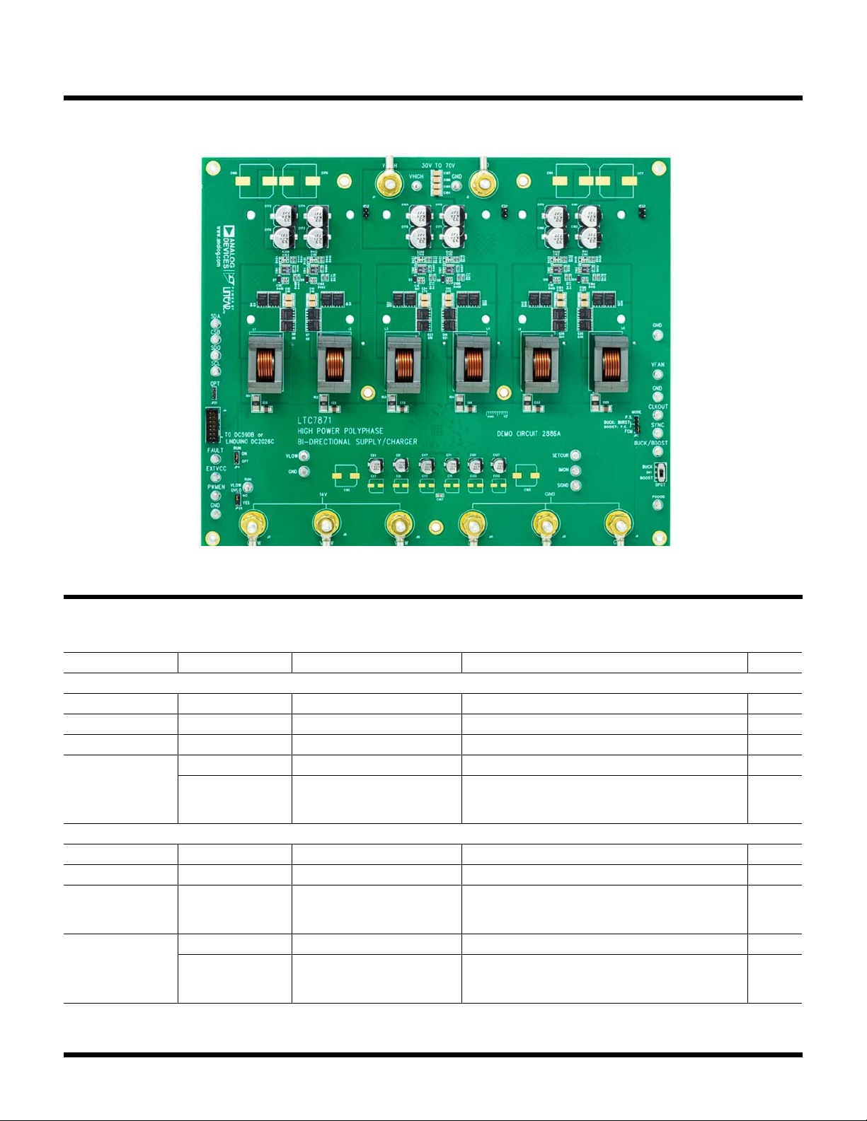
Analog Devices ADI Power LTC7871 Quick setup guide

1
DEMO MANUAL DC2886A
Rev. A
DESCRIPTION
LTC7871/LTC7060
48V-to-14V, 6-Phase, 2.5kW Bidirectional Supply/
Charger
All registered trademarks and trademarks are the property of their respective owners.
Demonstration circuit 2886A is a high power, high effi-
ciency six-phase bidirectional converter featuring the
LTC
®
7871 and LTC7060. The terminals labeled VHIGH
and VLOW are either inputs or outputs depending on the
direction of power flow. When the switch at SW1 is in the
BUCK position, VLOW provides a 14V output and VHIGH is
the input with a range of 30V to 70V. When the switch
is in the BOOST position, VHIGH provides a 48V output
and VLOW is the input with a range of 10V to 14V. The
maximum VLOW current is 180A in both directions. The
maximum output power is 2.5kW when operating as a
buck within the input voltage range. When operating as
a boost, the maximum output power is 2.4kW when the
input voltage is 14V. External airflow is required when
operating at maximum power. The MOSFETs in each
phase are driven by the LTC7060 half bridge driver. Each
LTC7060 gate driver is placed next to the MOSFETs and
receives a PWM signal from the LTC7871.
The inductor current for each phase is sensed with a low
1mΩ sense resistor using a highly accurate AC/DC cur-
rent sensing architecture with low power dissipation. The
LTC7871’s constant-current loop provides a DC current
limit for the current flowing in or out of the V
LOW
terminal
depending on the state of the BUCK pin. This current can
be programmed with the SETCUR pin and monitored with
the IMON pin.
The DC2886A provides a SPI compatible serial port. With
a DC2026C (Linduino
®
One) demo board and QuikEval™
software on a host computer, the user can:
• Margin the regulated VLOW or VHIGH up or down.
•Margin the DC current limit up or down with the
SETCUR pin.
•Adjust the frequency spread and modulation rate of
the spread spectrum circuit, when spread spectrum
isenabled.
•Monitor the operational status and faults of
theLTC7871.
Additional features of the DC2886A include:
• Pin selectable light load operating modes
– Buck:FCM, pulse-skipping and Burst Mode
®
Operation
– Boost: FCM and pulse-skipping
• SYNC and CLKOUT pins
•Optional jumper to enable spread spectrum modulation
• RUN, FAULT, PGOOD and PWNEN pins
•BUCK pin to externally control the direction of
powerflow
• Footprint for an optional heatsink
Design files for this circuit board are available.

2
DEMO MANUAL DC2886A
Rev. A
PERFORMANCE SUMMARY
Specifications are at TA= 25°C
SYMBOL PARAMETER CONDITIONS MIN TYP MAX UNITS
Buck Mode
VHIGH Supply Range 30 48 70 V
VLOW Output Voltage 13.6 14.0 14.4 V
ILOW(MAX) 180 A
fSWITCH Operating Frequency 150 kHz
Efficiency VHIGH = 48V
ILOW = 180A
400LFM Airflow
97.5 %
Boost Mode
VLOW Supply Range 10 12 14 V
VHIGH Output Voltage 46.9 48.4 49.8 V
IHIGH(MAX) VLOW = 14V
VLOW = 12V
VLOW = 10V
51
44
35
A
fSWITCH Operating Frequency 150 kHz
Efficiency VLOW = 14V
IHIGH = 51A
400LFM Airflow
97.2 %
BOARD PHOTO

3
DEMO MANUAL DC2886A
Rev. A
Figure1. Proper Measurement Equipment Setup for BUCK Mode
QUICK START PROCEDURE
Instructions for operating the DC2886A are below.
NOTE:Use short and thick cables with a sufficient current
rating. If batteries are used when testing the demo board,
always use suitable circuit breakers for safety.
Constant-Voltage (CV) Buck Mode
1. Refer to the connection diagram shown in Figure1.
2. Place SW1 in the BUCK position.
3. Connect the input supply to VHIGH and the load to
VLOW. Next connect the voltmeters to monitor VHIGH
and VLOW.
4. Turn on the V
HIGH
supply. With no load, slowly increase
the VHIGH supply until VHIGH reaches 30V. At this point,
14V should appear on VLOW. The regulation limits are
shown in the Performance Summary section.
5. Next, increase VHIGH to 48V. Recheck the regulation.
6. Apply load up to 180A across VLOW. Recheck
theregulation.
7. After the basic performance has been verified, the
other aspects of performance can be measured
andobserved.
NOTE:
MONITOR VHIGH ACROSS
C54 OR C61 FOR ACCURATE
EFFICIENCY MEASUREMENTS.
NOTE:
MONITOR VLOW ACROSS
C72 OR C66 FOR ACCURATE
EFFICIENCY MEASUREMENTS.
–
+
–
+
IHIGH
ILOW
VHIGH
SUPPLY
LOAD
–
+
PLACE SW1 IN BUCK POSITION
VLOW
VHIGH
+–
dc2886a F01

4
DEMO MANUAL DC2886A
Rev. A
5. Next, increase VLOW to 14V. Recheck the regulation.
6. Apply load up to 51A across VHIGH. Recheck
theregulation.
7. After the basic performance has been verified, the
other aspects of performance can be measured
andobserved.
Note:When measuring the output voltage or input
voltage ripple, be sure to measure directly across an
output or input capacitor. Do not use the ground lead
on the oscilloscope probe. See Figure3.
Constant-Voltage (CV) Boost Mode
1. Refer to the connection diagram in Figure2.
2. Place SW1 in the BOOST position.
3. Connect the input supply to VLOW and the load to
VHIGH. Next connect the voltmeters to monitor VLOW
and VHIGH.
4. Turn on the VLOW supply. With no load, slowly increase
the VLOW supply until VLOW reaches 10V. At this point,
48V should appear on the output. The regulation limits
are shown in the Performance Summary section.
Figure2. Proper Measurement Equipment Setup for BOOST Mode
NOTE:
MONITOR VHIGH ACROSS
C54 OR C61 FOR ACCURATE
EFFICIENCY MEASUREMENTS.
NOTE:
MONITOR VLOW ACROSS
C72 OR C66 FOR ACCURATE
EFFICIENCY MEASUREMENTS.
–
+
IHIGH
ILOW
PLACE SW1 IN BOOST POSITION
VLOW
VHIGH
+–
dc2886a F02
LOAD
–
+
–
+
VLOW
SUPPLY
QUICK START PROCEDURE

5
DEMO MANUAL DC2886A
Rev. A
Constant-Current (CC) Mode
The DC2886A can operate as a constant-current source
when operating either as a buck or a boost. There are the
setup instructions.
1. For buck operation, setup DC2886A as shown in
Figure 1. For boost operation, setup DC2886A as
shown in Figure2. The load will need to have a con-
stant-voltage mode.
2. If the converter is setup as a buck, the CV setting for
the load should be 10V or less. If the converter is setup
as a boost, the CV setting should be 40V or less.
3. Connect a bench voltage source to the SETCUR pin as
shown in Figure4. This could be either a DC voltage
or the output of a pulse generator.
4. Monitor SETCUR, IMON and ILOW or IHIGH while adjust-
ing the SETCUR voltage. Figure17 shows an example.
For buck to boost or boost to buck transition testing,
setup the DC2886A as shown in Figure5.
QUICK START PROCEDURE
+ –
VOUT GND
COUT
Figure3. How to Measure the Output or Input Voltage Ripple
DC VOLTAGE OR
PULSE
GENERATOR
dc2886a F04
+
–
DMM OR
OSCILLOSCOPE
ILOW(MAX) = SETCUR/(K • RSNS) • # PHASES
GIVEN: K = 20 (ILIM = ¾ V5), RSNS = 1mΩ, # PHASES = 6
ILOW(MAX) = SETCUR • 300
IMON = ILOW/300 + 1.25V
ILOW IS POSITIVE DURING BUCK OPERATION, NEGATIVE DURING BOOST OPERATION
Figure4. Using SETCUR Pin to Control DC Current

6
DEMO MANUAL DC2886A
Rev. A
External Bulk Capacitance
Additional bulk capacitance may be required across the
input for either power flow direction, especially if operating
at or near full load with supply cables longer than 2 feet.
Depending on the supply cable inductance, when operat-
ing as a boost, an extra 10mF of bulk capacitance across
VLOW may be required. When operating as a buck, an extra
1mF of bulk capacitance across VHIGH may be required.
For buck/boost transition testing, this extra capacitance
should be added across both inputs. Likely choices for
the external capacitance are either aluminum electrolytic
or super capacitors with sufficient voltage rating.
Thermal Considerations
With full continuous load on the output in either direc
-
tion at room temperature ambient, 400LFM of airflow
is recommended with full load. All the efficiency curves
and thermal images shown in the Typical Performance
Characteristics section were taken with this amount of
airflow from an adjustable external fan. To further aid with
thermals, the DC2886A has three optional footprints for
a board mounted heatsink and DC fan. The heatsinks are
placed at HS1–HS3 on the bottom layer underneath the
power stages for phases 1and 2, phases 3 and 4 and
phases 5 and 6. The DC fan is mounted over the heat-
sink. Terminals labeled V
FAN1
–V
FAN3
provide the fans with
power from VLOW. See Figure6 for details.
Figure5. Typical Setup for the Buck/Boost Transition Test
DC2886A
VLOW
dc2886a F05
VHIGH
GND
SETCUR
BUCK
+
–
+
E-LOAD
CV MODE
VLOW
SUPPLY
+
VHIGH
SUPPLY
E-LOAD
CV MODE
PULSE
GENERATOR
VSETCUR
IPROBE CLOW
~10mF
CHIGH
~1mF
QUICK START PROCEDURE
Figure6. DC2886A Optional Heatsink and Fan Mounting Assembly Drawing (Fan May Be
Powered from VLOW by Plugging Its Connector to the Terminals Labeled VFAN1 to VFAN3)
4–40 × 3/8” STANDOFF
4–40 × 1/2” SCREW
4–40 ×3/8” SCREW INSULATING WASHER
HEATSINK
60mm ×10mm FAN
INSULATING WASHER
PCB
COMPONENTS
THERMALLY CONDUCTIVE
INSULATION
SUGGESTED COMPONENTS:
FAN: DELTA ELECTRONICS EFB0612HHA
HEATSINK: AAVID THERMALLOY 241204B92200G

7
DEMO MANUAL DC2886A
Rev. A
SPI Interface
To control or monitor the DC2886A from QuikEval on a
host computer, follow these steps:
1. Refer to Figure7.
2. If QuikEval is already installed, download the latest
software by selecting Tools →Update Program. If
QuikEval is not installed, then click on this link.
3. Connect J6 of the DC2886A to a DC2026C with a 14-pin
ribbon cable.
4. Connect the DC2026C to the host computer with a
USBcable.
QUICK START PROCEDURE
5. Refer to the demo manual of the DC2026C for further
details.
6. Apply a voltage within the specified input range to
either VHIGH or VLOW depending on the direction of
power flow.
7. Start QuikEval on the host computer.
8. Use QuikEval to monitor and control the LTC7871. The
LTC7871 QuikEval GUI is shown in Figure8. The dash-
board is on the left and an optional design tool is on
the right.
a. To read the status, either press the Read Once button
or the Read Continuously button in the dashboard.
Figure7. Connecting the DC2886A to a Host Computer (Refer to DC2026C Demo Manual for More Details)
Figure8. LTC7871 QuikEval GUI (Design Tool Only Available When Enabled from the File Menu)
14-PIN
RIBBON
CABLE
USB
CABLE DC2026C*
(Linduino ONE)
HOST
COMPUTER/
QuikEval
dc2886a F07
DC2886A
NOTES:
POWER MUST BE APPLIED TO VLOW OR VHIGH
TO ALLOW COMMUNICATION BETWEEN THE
DC2886A AND THE DC2026C.
*THE DC2886A COULD BE CONNECTED TO EITHER
THE DC2026C OR DC590B, BUT THE DC2026C
IS PREFERRED FOR FUTURE USE.

8
DEMO MANUAL DC2886A
Rev. A
b. QuikEval can margin VLOW, VHIGH and the DC ILOW
current limit up or down by writing to the register
which controls the current source digital to ana-
log converter (IDAC) for the VFB
LOW
, VFB
HIGH
or
SETCUR pins. To use this feature, make sure the
Read Continuously button is not enabled. This but-
ton is gray when not enabled.
c. An optional design tool can be enabled from the
File menu. It calculates the required IDAC value to
margin the V
LOW
, V
HIGH
or DC I
LOW
current limit
to a given value. To use this tool, enter the values
for the feedback divider or SETCUR resistor and
then enter the value for the desired VLOW, VHIGH
or IL(MAX) which is the DC ILOW current limit. The
design tool will then provide the calculated IDAC
value. To update the LTC7871’s registers, enter the
calculated IDAC values in the dashboard and then
press the respective Update button.
QUICK START PROCEDURE
TYPICAL PERFORMANCE CHARACTERISTICS
LOAD CURRENT (A)
0
EFFICIENCY (%)
93
99
97
95
100
98
96
94
100 18060 140
dc2886a F09
20080 16040 12020
AIRFLOW = 400LFM
30VHIGH
48VHIGH
70VHIGH
VLOW = 14V
LOAD CURRENT (A)
0
EFFICIENCY (%)
93
99
97
95
100
98
96
94
100 18060 140
dc2886a F10
20080 16040 12020
AIRFLOW = 400LFM
VLOW ADJUSTED THROUGH
SPI INTERFACE
14VLOW
12VLOW
10VLOW
VHIGH = 48V
LOAD CURRENT (A)
0
EFFICIENCY (%)
93
99
97
95
100
98
96
94
25 4515 35
dc2886a F11
50 5520 4010 305
14VLOW
12VLOW
10VLOW
AIRFLOW = 400LFM
VHIGH = 48V
LOAD CURRENT (A)
0
EFFICIENCY (%)
93
99
97
95
100
98
96
94
25 4515 35
dc2886a F12
50 5520 4010 305
40VHIGH
48VHIGH
56VHIGH
AIRFLOW = 400LFM
VHIGH ADJUSTED THROUGH
SPI INTERFACE
VLOW = 12V
|ILOW| (A)
0
POWER LOSS (W)
10
70
50
30
80
60
40
20
0100 18060 140
dc2886a F13
20080 16040 12020
AIRFLOW = 400LFM
ILOW+(BUCK)
ILOW–(BOOST)
BOOST
BUCK
Figure9. Efficiency While Operating
as a BUCK, Input Voltage Varied,
Converter Setup for FCM, External
Fan Is Used
Figure10. Efficiency While
Operating as a BUCK, Output Voltage
Varied, Converter Setup for FCM,
External Fan Is Used
TA= 25°C, unless otherwise noted.
Figure11. Efficiency While
Operating as a BOOST, Input
Voltage Varied, Converter Setup for
FCM, External Fan Is Used
Figure12. Efficiency While
Operating as a BOOST, Output
Voltage Varied, Converter Setup for
FCM, External Fan Is Used
Figure13. Buck vs Boost Power
Loss Comparison, VHIGH = 48V,
VLOW = 14V, External Fan Is Used

9
DEMO MANUAL DC2886A
Rev. A
TYPICAL PERFORMANCE CHARACTERISTICS
dc2886a F14
AIRFLOW
VHIGH
VLOW
PH6
PH1
L
QB
QT
dc2886a F15
AIRFLOW
VHIGH
VLOW
PH6
PH1
L
QB
QT
dc2886a F16
IMON
200mV/DIV
SETCUR
200mV/DIV
VLOW
10V/DIV
ILOW
50A/DIV
50A
1.28V
10A
20ms/DIV
Boost–to–Buck Transition
50µs/DIV
BUCK
5V/DIV
dc2886a F17
VLOW
2V/DIV
IL
5A/DIV
VHIGH
2V/DIV
VSW
100V/DIV
Figure14. Thermal Image While Operating as a BUCK,
VHIGH = 48V, VLOW = 14V, Load = 180A, Airflow = 400LFM,
External Fan Is Used, DRVCC = 10V, fSWITCH = 150kHz, TA= 23°C
Figure15. Thermal Image While Operating as a BOOST,
VLOW = 14V, VHIGH = 48V, Load = 51A, Airflow = 400LFM,
External Fan Is Used, DRVCC = 10V, fSWITCH = 150kHz, TA= 23°C
Figure16. ILOW Stepped from 10A to 50A with the SETCUR Pin
While Operating in CC BUCK Mode, VHIGH = 48V, VLOW Clamped
at 10V with Electronic Load, 2× 10mF Bulk Capacitance Across
VLOW. ILIM = Float
Figure17. Boost to Buck Transition of the DC2886A Demo Board,
ILOW = 0A, VLOW Clamped at 10V, VHIGH Clamped at 40V

10
DEMO MANUAL DC2886A
Rev. A
PARTS LIST
ITEM QTY REFERENCE PART DESCRIPTION MANUFACTURER/PART NUMBER
Required Circuit Components
1 1 R7 RES., 10k , 5%, 1/10W, 0603 SAMSUNG, RC1608J103CS
YAGEO, RC0603JR-0710KL
2 1 R10 RES., 1k , 5%, 1/10W, 0603 SAMSUNG, RC1608J102CS
YAGEO, RC0603JR-071KL
3 6 R67, R400, R403, R406, R409, R412 RES., 1Ω, 1%, 1/10W, 0603 YAGEO, RC0603FR-071RL
4 1 R36 RES., 48.7k , 1%, 1/10W, 0603, AEC-Q200 PANASONIC, ERJ3EKF4872V
VISHAY, CRCW060348K7FKEA
5 6 R39, R40, R43, R49, R93, R103 RES., 1.5k , 1%, 1/10W, 0603 NIC, NRC06F1501TRF
VISHAY, CRCW06031K50FKEA
6 8 R18, R123, R398, R399, R402,
R405, R408, R411
RES., 100k , 1%, 1/10W, 0603, AEC-Q200 NIC, NRC06F1003TRF
PANASONIC, ERJ3EKF1003V
VISHAY, CRCW0603100KFKEA
7 1 R430 RES., 12.7k , 1%, 1/10W, 0603, AEC-Q200 PANASONIC, ERJ3EKF1272V
VISHAY, CRCW060312K7FKEA
8 6 RS1, RS2, RS3, RS4, RS5, RS6 RES., 0.001Ω, 1%, 1W, 2512, METAL, SENSE,
AEC-Q200
VISHAY, WSL25121L000FEA
9 5 R8, R9, R418, R428, R469 RES., 10k , 1%, 1/10W, 0603, AEC-Q200 KOA SPEER, RK73H1JTTD1002F
PANASONIC, ERJ3EKF1002V
VISHAY, CRCW060310K0FKEA
VISHAY, CRCW060310K0FKEB
10 2 R454, R455 RES., 0.01Ω, 1%, 1/2W, 1210, SENSE, AEC-Q200 YAGEO, RL1210FR-070R01L
11 1 R431 RES., 499k , 1%, 1/8W, 0805, AEC-Q200 NIC, NRC10F4993TRF
PANASONIC, ERJ6ENF4993V
VISHAY, CRCW0805499KFKEA
12 1 R29 RES., 2.2Ω, 1%, 1/4W, 1206, AEC-Q200 VISHAY, CRCW12062R20FKEA
13 1 R44 RES., 37.4k , 1%, 1/10W, 0603, AEC-Q200 PANASONIC, ERJ-3EKF3742
PANASONIC, ERJ3EKF3742V
VISHAY, CRCW060337K4FKEA
14 1 R1 RES., 3.01MΩ, 1%, 1/8W, 0805, AEC-Q200 VISHAY, CRCW08053M01FKEA
15 1 R2 RES., 210k , 1%, 1/8W, 0805, AEC-Q200 VISHAY, CRCW0805210KFKEA
16 6 R31, R32, R53, R65, R97, R98 RES., 16.9k , 1%, 1/8W, 0805, AEC-Q200 STACKPOLE ELECT., INC., RMCF0805FT16K9
VISHAY, CRCW080516K9FKEA
17 6 R419, R420, R421, R422, R423,
R424
RES., 10Ω, 1%, 1/10W, 0603 NIC, NRC06F10R0TRF
PANASONIC, ERJ3EKF10R0V
ROHM, MCR03EZPFX10R0
VISHAY, CRCW060310R0FKEA
YAGEO, RC0603FR-0710RL
18 1 R11 RES., 3.01k , 1%, 1/10W, 0603 VISHAY, CRCW06033K01FKEA
YAGEO, RC0603FR-073K01L
19 1 R17 RES., 30.1k , 1%, 1/10W, 0603, AEC-Q200 PANASONIC, ERJ3EKF3012V
VISHAY, CRCW060330K1FKEA

11
DEMO MANUAL DC2886A
Rev. A
ITEM QTY REFERENCE PART DESCRIPTION MANUFACTURER/PART NUMBER
20 39 R19, R397, R401, R404, R407,
R410, R413, R426, R429, R432,
R433, R434, R435, R436, R437,
R442, R443, R444, R445, R446,
R447, R448, R449, R450, R451,
R452, R453, R467, R468, R470,
R471, R472, R473, R474, R475,
R476, R477, R478, R479
RES., 0Ω, 1/10W, 0603 BOURNS, CR0603-J/-000ELF
VISHAY, CRCW06030000Z0EAC
YAGEO, RC0603FR-070RL
21 2 R425, R438 RES., 45.3k , 1%, 1/10W, 0603, AEC-Q200 PANASONIC, ERJ3EKF4532V
VISHAY, CRCW060345K3FKEA
22 6 R38, R41, R42, R50, R94, R112 RES., 1.69k , 1%, 1/10W, 0603, AEC-Q200 NIC, NRC06F1691TRF
PANASONIC, ERJ3EKF1691
VISHAY, CRCW06031K69FKEA
23 1 R15 RES., 130k , 1%, 1/8W, 0805 NIC, NRC10F1303TRF
24 1 R427 RES., 107k , 1%, 1/8W, 0805 VISHAY, CRCW0805107KFKEA
25 2 C11, C189 CAP., 47pF, C0G, 50V, 5%, 0603 KEMET, C0603C470J5GACTU
MURATA, GRM1885C1H470JA01D
TDK, CGJ3E2C0G1H470J080AA
VISHAY, VJ0603A470JXAAC
26 7 C22, C25, C66, C72, C129, C133,
C188
CAP., 10µF, X7R, 25V, 10%, 1210 AVX, 12103C106KAT2A
MURATA, GRM32DR71E106KA12L
27 7 C105, C150, C151, C154, C157,
C160, C163
CAP., 1µF, X7R, 25V, 10%, 0603, AEC-Q200 MURATA, GCM188R71E105KA64D
TAIYO YUDEN, TMK107AB7105KAHT
TDKCGA3E1X7R1E105K080AC
28 12 C46, C149, C152, C153, C155,
C156, C158, C159, C161, C162,
C164, C165
CAP., 0.22µF, X7R, 25V, 10%, 0603 MURATA, GRM188R71E224KA88D
TDK, C1608X7R1E224K080AC
YAGEO, CC0603KRX7R8BB224
29 15 C6, C7, C9, C28, C29, C32, C33,
C34, C35, C45, C48, C122, C123,
C125, C140
CAP., 0.1µF, X7R, 25V, 10%, 0603, AEC-Q200 AVX, 06033C104K4T4A
SAMSUNG, CL10B104KA8WPNC
30 12 C170, C171, C172, C173, C174,
C175, C178, C179, C180, C181,
C182, C183
CAP., 33µF, ALUM. ELECT. HYB., 80V, 20%, 10mm ×
10.2mm, RADIAL, AEC-Q200
PANASONIC, EEHZC1K330P
31 3 C10, C31, C107 CAP., 4.7µF, X7R, 16V, 10%, 0805 AVX, 0805YC475KAT2A
KEMET, C0805C475K4RACTU
MURATA, GRM21BR71C475KA73L
NIC, NMC0805X7R475K16TRPLPF
TAIYO YUDEN, EMK212B7475KG-T
32 6 C21, C24, C47, C74, C131, C137 CAP., 100µF, ALUM POLY HYB, 25V, 20%, 6.3mm ×
7.7mm, D8, SMD, RADIAL, AEC-Q200
PANASONIC, EEHZA1E101XP
33 1 C12 CAP., 10pF, C0G, 100V, ±0.1pF, 0603 AVX, 06031A100BAT2A
KEMET, C0603C100B1GAC
34 16 C14, C15, C16, C19, C54, C55,
C61, C75, C124, C127, C128, C136,
C184, C185, C186, C187
CAP., 2.2µF, X7R, 100V, 10%, 1210 AVX, 12101C225KAT2A
MURATA, GRM32ER72A225KA35,
GRM32ER72A225KA35L
NIC, NMC1210X7R225K100TRPLPF
TDK, C3225X7R2A225K230AB
PARTS LIST

12
DEMO MANUAL DC2886A
Rev. A
ITEM QTY REFERENCE PART DESCRIPTION MANUFACTURER/PART NUMBER
35 1 C5 CAP., 47pF, C0G, 50V, 10%, 0603 AVX, 06035A470KAT2A
KEMET, C0603C470K5GACTU
VISHAY, VJ0603A470KXAAC
36 1 C39 CAP
., 1µF, X7R, 100V, 10%, 1206 AVX, 12061C105KAT2A
MURATA, GRM31CR72A105KA01L
37 6 L1, L2, L3, L4, L5, L6 IND., 6.8µH, PWR, CHOKE, 20%, 41A, 2mΩ,
4-TERM, THT, AEC-Q200
SAGAMI ELEC CO., LTD., CVE2622C-6R8M-R
38 6 D3, D7, D8, D9, D10, D11 DIODE, SCHOTTKY, 100V, 1A, POWERDI-123 DIODES INC., DFLS1100-7
39 1 D12 DIODE, SCHOTTKY, 20V, 2A, SOD-323F NEXPERIA, PMEG2020EJ, 115
40 12 Q1, Q2, Q3, Q4, Q17, Q20, Q22,
Q24, Q37, Q39, Q40, Q42
XSTR., MOSFET, N-CH, 80V, 49A, PG-TDSON-8 INFINEON, BSC117N08NS5,
BSC117N08NS5ATMA1
41 12 Q5, Q6, Q7, Q8, Q18, Q19, Q21,
Q23, Q35, Q36, Q38, Q41
XSTR., MOSFET, N-CH, 80V, 95A, PG-TDSON-8 INFINEON, BSC052N08NS5,
BSC052N08NS5ATMA1
42 6 U1, U2, U3, U4, U5, U6 IC, DC/DC CONVERTER, MSE-12 ANALOG DEVICES, LTC7060EMSE#PBF,
LTC7060EMSE#TRPBF
43 1 U7 IC, HIGH POWER POLY-PHASE, BIDIRECTIONAL
SUPPLY/CHARGER
ANALOG DEVICES, LTC7871ELWE#PBF
SPI Interface
1 3 R439, R440, R441 RES., 4.99k , 1%, 1/10W, 0603 PANASONIC, ERJ3EKF4991V
YAGEO, RC0603FR-074K99L
2 1 R417 RES., 100Ω, 1%, 1/10W, 0603, AEC-Q200 NIC, NRC06F1000TRF
PANASONIC, ERJ3EKF1000V
VISHAY, CRCW0603100RFKEA
3 3 R12, R415, R416 RES., 100Ω, 1%, 1/10W, 0603, AEC-Q200 NIC, NRC06F1000TRF
PANASONIC, ERJ3EKF1000V
VISHAY, CRCW0603100RFKEA
4 1 C169 CAP
., 0.1µF, X7R, 25V, 10%, 0603, AEC-Q200 AVX, 06033C104K4T4A
SAMSUNG, CL10B104KA8WPNC
5 1 U8 IC, MEMORY, EEPROM, 2Kb (256x8), TSSOP-8, 400kHz MICROCHIP, 24LC025-I/ST, 24LC025T-I/ST
Additional Circuit Components
1 0 R20, R414, R456, R457, R458,
R459, R460, R461, R462, R463
RES., OPTION, 0603
2 0 R464, R465, R466 RES., OPTION, 0805
3 0 C192, C193 CAP., OPTION, ALUM. ELECT., SMD
4 0 C176, C177, C190, C191 CAP., 100µF, ALUM. ELECT., 100V, 10%, 16mm ×
16.5mm SMD
SUN ELECTRONIC INDUSTRIES CORP,
100CE100KXT+D
5 0 C148, C166, C167, C194, C195,
C196
CAP., OPTION, 0603
6 0 C20, C27, C73, C76, C132, C135 CAP
., OPTION, ALUM. ELECT., SMD
7 0 Z1 DIODE, OPTION, SOD-123
8 0 D13, D14 DIODE, OPTION, SOD-323
9 0 C168 CAP., 15µF, TANT, 16V, 20%, 3528 KEMET, T521B156M016ATE090
PARTS LIST

13
DEMO MANUAL DC2886A
Rev. A
ITEM QTY REFERENCE PART DESCRIPTION MANUFACTURER/PART NUMBER
Hardware
1 1 J6 CONN., HDR, SHROUDED, MALE, 2×7, 2mm, VERT,
ST, THT
MOLEX, 87831-1420
2 3 XJP3, XJP10, XJP11 CONN., SHUNT, FEMALE, 2-POS, 2mm SAMTEC, 2SN-BK-G
3 1 JP3 CONN., HDR., MALE, 1×4, 2mm, THT, STR SULLINS CONNECTOR SOLUTIONS,
NRPN041PAEN-RC
4 3 JP4, JP21, JP25 CONN., HDR., MALE, 1×3, 2mm, THT, STR, NO
SUBS. ALLOWED
SAMTEC, TMM-103-02-L-S
5 3 JP22, JP23, JP24 CONN., HDR, MALE, 1×2, 2.54mm, VERT, ST, THT WURTH, 61300211121
6 23 E1, E2, E3, E4, E5, E9, E11, E12, E14,
E15, E20, E21, E22, E23, E25, E27,
E28, E29, E30, E31, E32, E33, E34
TEST POINT, TURRET, 0.094 MTG. HOLE, PCB
0.062THK
MILL-MAX, 2501-2-00-80-00-00-07-0
7 1 SW1 SWITCH, SLIDE, DPDT, 0.3A, 6VDC, PTH C&K, JS202011CQN
8 8 J1, J2, J5, J7, J8, J9, J10, J11 EVAL BOARD STUD HARDWARE SET, #10-32
9 9 X1, X2, X3, X4, X5, X6, X16, X17, X18 STANDOFF, NYLON, SNAP-ON, 0.25 (6.4mm) KEYSTONE, 8831
WURTH, 70293100
PARTS LIST

14
DEMO MANUAL DC2886A
Rev. A
SCHEMATIC DIAGRAM
A
A
B
B
C
C
D
D
E
E
4 4
3 3
2 2
1 1
TO DC590B or
LINDUINO DC2026C
Note:
ILIM SETTING is 3/4 * V5
IDENTITY EEPROM
OPT
3528
Fsw = 150kHz, typical
VHIGH
V5
VLOW
V5
V5
V5
VHIGH
V5
V5
VLOW
V5
DRVCC
V5
VLOW
VHIGH
V5
VHIGH
VLOW
SDC1
SDC2
SDC3
SDC4
SDC5
SDC6
SAC1
SAC2
SAC3
SAC4
SAC5
SAC6
PWM1
PWM2
PWM3
PWM4
PWM5
PWM6
PWMEN
SN1
SN2
SN3
SN4
SN5
SN6
DATE:
SHEET OF
TITLE: SCHEMATIC
APPROVALS
PCB DES.
APP ENG.
Phone: (408)432-1900
SIZE:
SCHEMATIC NO. AND REVISION:
CUSTOMER NOTICE
THIS CIRCUIT IS PROPRIETARY TO ANALOG DEVICES AND
SUPPLIED FOR USE WITH ANALOG DEVICES PARTS.
www.analog.com
SKU NO.
IC NO.
ANALOG DEVICES HAS MADE A BEST EFFORT TO DESIGN A
CIRCUIT THAT MEETS CUSTOMER-SUPPLIED SPECIFICATIONS;
HOWEVER, IT REMAINS THE CUSTOMER'S RESPONSIBILITY TO
VERIFY PROPER AND RELIABLE OPERATION IN THE ACTUAL
APPLICATION. COMPONENT SUBSTITUTION AND PRINTED
CIRCUIT BOARD LAYOUT MAY SIGNIFICANTLY AFFECT CIRCUIT
PERFORMANCE OR RELIABILITY. CONTACT ANALOG DEVICES
APPLICATIONS ENGINEERING FOR ASSISTANCE.
12
HZ
MIKE S.
LTC7871-LXE
HIGH POWER POLY-PHASE BI-DIRECTIONAL SUPPLY/CHARGER
DC2886A
710-DC2886A_REV06
N/A
Monday, June 08, 2020
R123
100k
R8 10K
1%
R11
3.01k 1%
C148
OPT
R29
2.2
1206
1%
R440
4.99k
JP25
NO
YES
VLOW UVLO
1
3
2
E9
FAULT
R7
10k
R439
4.99k
R44
37.4k
C195
OPT
R1
3.01M
1%
U7
LTC7871-LWE
SS
1
ITHHIGH
6
VFBHIGH 7
V5 9
OVHIGH 13
UVHIGH 14
SGND 5
ITHLOW
4
VFBLOW 3
IMON
10
OVLOW
15
SNSD2+ 20
SETCUR
11
SNSA1+ 17
RUN
27
FAULT
35
BUCK
54
ILIM
49
SNSD1+ 19
SNS1- 18
SNS2- 21
SNSA2+ 22
DRVSET
44
PWM1
29
SDO
38
SDI
39
SCLK
40
CSB
37
EXTVCC 42
DRVCC 46
PWM2
31
VHIGH 48
PWM3
32
PWMEN
28
PWM4
33
SNS3- 24
SNSD3+ 25
SNSA3+ 23
NC
26
PWM5
34
CLKOUT
50
SYNC
52
FREQ
53
MODE
51
PWM6
36
PGOOD 30
SGND 45
NC
2
NC
8
NC
12
NC
41
NC
43
NC
47
NC
55
SNS4- 57
SNSD4+ 56
SNSA4+ 58
SNS5- 60
SNSD5+ 61
SNSA5+ 59
SNS6- 63
SNSD6+ 62
SNSA6+ 64
SGND 16
SGND 65
C9 0.1uF
R414
OPT
R15
130k
1%
0805
E15
GND
C196
OPT
R9
10K
1%
C6 0.1uF
C39
1uF
100V
1206
JP4
ON
OFF
RUN
1
3
2
E14
GND
R430
12.7k
C11 47pF E1
EXTVCC
E32
SDA
R17
30.1k
SW1
DPDT
BUCK
BOOST
1
2
3
4
5
6
+
C168
OPT
R416 100
R2
210k
1%
0805
E21
SYNC
R438
45.3k
E30
SDO
E22
PWMEN
E5
SETCUR
C12
10pF
R36
48.7k
1%
C105
1uF
C189
47pF
R441
4.99k
R20
OPT
J6
V+ 1
3.3V or 5V 2
GND 3
SCK/SCL 4
MISO 5
CS 6
MOSI/SDA 7
GND 8
EESDA 9
EEVCC 10
EESCL 11
EEGND 12
GND 13
GPIO_1 14
R464
OPT
0805
E29
SCL
R417 1k
R466
OPT
D14
OPT
2 1
E3
CLKOUT
C7 0.1uF
R469 10K
1%
E31
CSB
R18
100k
R457
OPT
D13
OPT
R428
10K
E25
SGND
R431
499k
0805
R418
10K
C5 47pF
U8
24LC025-I/ST
A0 1
A1 2
A2 3
GND
4
SDA
5
SCL 6
WP 7
VCC 8
JP3
P.S.
BUCK: BURST
FCM
MODE
BOOST: P.S.
1
3
2
4
E2
IMON
C31
4.7uF
16V
0805
R429
0
R425
45.3k
JP21
1
3
2
C169
0.1uF
R465
OPT
0805
R10
1k
C166
OPT
C167
OPT
E33
PGOOD
R415 100
D12 PMEG2020EJ
E34
RUN
R456
OPT
R426
0
Z1
OPT
1
2
R19
0
C194
OPT
R427
107k
0805
E4
BUCK/BOOST
R12 100
C10
4.7uF
0805
RUN
PGOOD
PWM1
PWM2
PWM3
PWM4
PWM5
PWM6
SN1
SN3
SN4
SN5
SN6
SDC1
SAC1
SAC2
SDC2
SAC3
SDC3
SAC4
SDC4
SAC5
SDC5
SAC6
SDC6
CSB
SDO
SDA
SCL
SCL
SDA
CSB
SDO
DRVCC
SN2
RUN
PGOOD
RUN

15
DEMO MANUAL DC2886A
Rev. A
Information furnished by Analog Devices is believed to be accurate and reliable. However, no responsibility is assumed by Analog
Devices for its use, nor for any infringements of patents or other rights of third parties that may result from its use. Specifications
subject to change without notice. No license is granted by implication or otherwise under any patent or patent rights of Analog Devices.
SCHEMATIC DIAGRAM
A
A
B
B
C
C
D
D
E
E
4
4
3
3
2
2
1
1
CVE2622H
CVE2622H
CVE2622H
CVE2622H
CVE2622H
CVE2622H
25V
1210
X5R
1210
X5R
25V
1210
X5R
25V
1210
X5R
25V
X5R
25V
1210
X5R
25V
1210
14V/180A
Optional DCR sensing components
When operating as a
CV boost converter,
10mF or more of
external bulk
capacitance is
recommended across
VLOW.
Note: JP22 – JP24 are for optional DC fans.
VHIGH
VHIGH
VLOW
VLOW
VHIGH
VLOW
VHIGH
VLOW
VHIGH
VLOW
VHIGH
VLOW
DRVCC
VHIGH
VHIGH
VLOW
VLOW
VLOW
VLOW
PWM5
PWM2
PWM1
PWM3
PWM4
PWM6
SAC1
SAC2
SAC3
SAC4
SAC5
SAC6
SDC1
SDC2
SDC3
SDC4
SDC5
SDC6
SN1
SN2
SN3
SN4
SN5
SN6
PWMEN
DATE:
SHEET OF
TITLE: SCHEMATIC
APPROVALS
PCB DES.
APP ENG.
Phone: (408)432-1900
SIZE:
SCHEMATIC NO. AND REVISION:
CUSTOMER NOTICE
THIS CIRCUIT IS PROPRIETARY TO ANALOG DEVICES AND
SUPPLIED FOR USE WITH ANALOG DEVICES PARTS.
www.analog.com
SKU NO.
IC NO.
ANALOG DEVICES HAS MADE A BEST EFFORT TO DESIGN A
CIRCUIT THAT MEETS CUSTOMER-SUPPLIED SPECIFICATIONS;
HOWEVER, IT REMAINS THE CUSTOMER'S RESPONSIBILITY TO
VERIFY PROPER AND RELIABLE OPERATION IN THE ACTUAL
APPLICATION. COMPONENT SUBSTITUTION AND PRINTED
CIRCUIT BOARD LAYOUT MAY SIGNIFICANTLY AFFECT CIRCUIT
PERFORMANCE OR RELIABILITY. CONTACT ANALOG DEVICES
APPLICATIONS ENGINEERING FOR ASSISTANCE.
22
HZ
MIKE S.
LTC7871-LXE
HIGH POWER POLY-PHASE BI-DIRECTIONAL SUPPLY/CHARGER
DC2886A
710-DC2886A_REV06
N/A
Monday, June 08, 2020
C66
10uF
Q39
BSC117N08NS5
52
4
1
3
D9
DFLS1100
R461
OPT
+
C27
OPT
RS4
0.001
R397
0
E23 VLOW
R449 0
R478 0
R97
16.9k
R421 10
1%
J7
VLOW
D8
DFLS1100
C165
0.22uF
+
C20
OPT
R432
0
C184
2.2uF
100V
C22
10uF
+
C181
33uF
80V
J8
VLOW
R424 10
1%
R445 0
C107
4.7uF
0805
C29 0.1uF
Q38
BSC052N08NS5
52
4
1
3
+
C171
33uF
80V
C187
2.2uF
100V
Q2
BSC117N08NS5
52
4
1
3
+
C174
33uF
80V
+
C190
OPT
C35
0.1uF
R479 0
C163
1uF
Q22
BSC117N08NS5
52
4
1
3
Q42
BSC117N08NS5
52
4
1
3
E20
GND
+
C191
OPT
C61 2.2uF
+
C175
33uF
80V
R32
16.9k
R98
16.9k
JP24
VFAN3
+
C182
33uF
80V
R413
0
R103
1.5k
J2
GND
R38 1.69k
C55
2.2uF
100V
R31
16.9k
1%
C28 0.1uF
R453 0
Q5
BSC052N08NS5
52
4
1
3
C151
1uF
R462
OPT
+
C47
100uF
U6
LTC7060-MSE
PWM
1
EN
2
FLTB
3
DT
4
Vcc
5
BGVcc
6BGRTN 7
SW 10
TG 11
BST 12
BG 8
NC 9
13
PGND
J5
GND
C153
0.22uF
Q6
BSC052N08NS5
52
4
1
3
C140 0.1uF
Q18
BSC052N08NS5
52
4
1
3
+
C179
33uF
80V
+
C21
100uF
Q41
BSC052N08NS5
52
4
1
3
E12 GND
C127
2.2uF
100V
R411 100k 1%
+
C74
100uF
R398 100k 1%
Q35
BSC052N08NS5
52
4
1
3
JP23
VFAN2
J10
VLOW
R463
OPT
R419 10
1%
R65
16.9k
R467 0
C162
0.22uF
+
C24
100uF
Q8
BSC052N08NS5
52
4
1
3
C14 2.2uF
C75
2.2uF
R401
0
C128
2.2uF
100V
+
C177
OPT
Q17
BSC117N08NS5
52
4
1
3
+
C76
OPT
R436
0
C160
1uF
R399 100k 1%
C159
0.22uF
Q21
BSC052N08NS5
52
4
1
3
R50 1.69k
U5
LTC7060-MSE
PWM
1
EN
2
FLTB
3
DT
4
Vcc
5
BGVcc
6BGRTN 7
SW 10
TG 11
BST 12
BG 8
NC 9
13
PGND
R41 1.69k
J11
GND
E11 VHIGH
R410
0
R454
0.01
RL1210FR-070R01L
1% JP22
VFAN1
C156
0.22uF
R42 1.69k
R474 0
R437
0
R422 10
1%
C157
1uF
Q3
BSC117N08NS5
52
4
1
3
R93
1.5k
L5 6.8uH
R472 0
C129
10uF
Q19
BSC052N08NS5
52
4
1
3
D3
DFLS1100
R448 0
C149
0.22uF
U2
LTC7060-MSE
PWM
1
EN
2
FLTB
3
DT
4
Vcc
5
BGVcc
6BGRTN 7
SW 10
TG 11
BST 12
BG 8
NC 9
13
PGND
R67
1
C164
0.22uF
R407
0
C154
1uF
C46
0.22uF
R94 1.69k
C16
2.2uF
100V
+
C183
33uF
80V
R475 0
R408 100k 1%
+
C131
100uF
R404
0
U1
LTC7060-MSE
PWM
1
EN
2
FLTB
3
DT
4
Vcc
5
BGVcc
6BGRTN 7
SW 10
TG 11
BST 12
BG 8
NC 9
13
PGND
C45 0.1uF
+
C178
33uF
80V
R49
1.5k
C72
10uF
R470 0
R473 0
R43
1.5k
R412
1
R39
1.5k
J1
VHIGH
30V TO 70V
R458
OPT
Q36
BSC052N08NS5
52
4
1
3
R405 100k 1%
Q20
BSC117N08NS5
52
4
1
3
+
C192
OPT
J9
GND
C133
10uF
R471 0
R402 100k 1%
R455
0.01
RL1210FR-070R01L
1%
R400 1
+
C180
33uF
80V
R112 1.69k
+
C132
OPT
Q37
BSC117N08NS5
52
4
1
3
R420 10
1%
RS5
0.001
R423 10
1%
C15
2.2uF
U3
LTC7060-MSE
PWM
1
EN
2
FLTB
3
DT
4
Vcc
5
BGVcc
6BGRTN 7
SW 10
TG 11
BST 12
BG 8
NC 9
13
PGND
R442 0
R40
1.5k
R447 0
RS2
0.001
D11
DFLS1100
C152
0.22uF
L6 6.8uH
C161
0.22uF
R452 0
+
C193
OPT
R450 0
L46.8uH
E27 VFAN
Q4
BSC117N08NS5
52
4
1
3
Q7
BSC052N08NS5
52
4
1
3
C122
0.1uF
R433
0
+
C135
OPT
C48 0.1uF
RS1
0.001
C25
10uF
L3 6.8uH
R444 0
L26.8uH
R459
OPT
D7
DFLS1100
C158
0.22uF
R446 0
R409
1
C136 2.2uF
R476 0
Q24
BSC117N08NS5
52
4
1
3
Q1
BSC117N08NS5
52
4
1
3
C185
2.2uF
100V
C155
0.22uF
C150
1uF
+
C176
OPT
C19
2.2uF
100V
+
C173
33uF
80V E28 GND
U4
LTC7060-MSE
PWM
1
EN
2
FLTB
3
DT
4
Vcc
5
BGVcc
6BGRTN 7
SW 10
TG 11
BST 12
BG 8
NC 9
13
PGND
C33
0.1uF
R451 0
R406
1
C188
10uF
Q23
BSC052N08NS5
52
4
1
3
R477 0
+
C137
100uF
+
C170
33uF
80V
C32
0.1uF
R468 0
RS6
0.001
R53
16.9k
R403
1
C123
0.1uF R434
0
+
C73
OPT
C54
2.2uF
100V
RS3
0.001
Q40
BSC117N08NS5
52
4
1
3
D10
DFLS1100
R460
OPT
C34
0.1uF
C186
2.2uF
100V
R443 0
C125 0.1uF
R435
0
+
C172
33uF
80V
C124
2.2uF
L1
6.8uH
SDC3
SAC3
SAC4
SDC4
DRVCC
PWMEN
DRVCC
PWM3
SAC1
SDC1
DRVCC
PWMEN
PWM1
SAC2
SDC2
DRVCC
DRVCC
PWMEN
PWM2
DRVCC
PWMEN
DRVCC
DRVCC
PWMEN
DRVCC
DRVCC
PWMEN
DRVCC
PWM6
SDC5
SAC5
SAC6
SDC6
DRVCC
DRVCC
DRVCC DRVCC
DRVCC
DRVCC
DRVCC
SN1
SN2
SN3
SN4
SN5
SN6
PWMEN
PWM5
SAC1
SAC6
SAC5
SAC4
SAC3
SAC2
SDC1
SDC6
SDC5
SDC4
SDC3
SDC2

16
DEMO MANUAL DC2886A
Rev. A
ANALOG DEVICES, INC. 2021
04/21
www.analog.com
ESD Caution
ESD (electrostatic discharge) sensitive device. Charged devices and circuit boards can discharge without detection. Although this product features patented or proprietary protection
circuitry, damage may occur on devices subjected to high energy ESD. Therefore, proper ESD precautions should be taken to avoid performance degradation or loss of functionality.
Legal Terms and Conditions
By using the evaluation board discussed herein (together with any tools, components documentation or support materials, the “Evaluation Board”), you are agreeing to be bound by the terms and
conditions set forth below (“Agreement”) unless you have purchased the Evaluation Board, in which case the Analog Devices Standard Terms and Conditions of Sale shall govern. Do not use the Evaluation
Board until you have read and agreed to the Agreement. Your use of the Evaluation Board shall signify your acceptance of the Agreement. This Agreement is made by and between you (“Customer”)
and Analog Devices, Inc. (“ADI”), with its principal place of business at One Technology Way, Norwood, MA 02062, USA. Subject to the terms and conditions of the Agreement, ADI hereby grants to
Customer a free, limited, personal, temporary, non-exclusive, non-sublicensable, non-transferable license to use the Evaluation Board FOR EVALUATION PURPOSES ONLY. Customer understands and
agrees that the Evaluation Board is provided for the sole and exclusive purpose referenced above, and agrees not to use the Evaluation Board for any other purpose. Furthermore, the license granted
is expressly made subject to the following additional limitations:Customer shall not (i) rent, lease, display, sell, transfer, assign, sublicense, or distribute the Evaluation Board;and (ii) permit any Third
Party to access the Evaluation Board. As used herein, the term “Third Party”includes any entity other than ADI, Customer, their employees, affiliates and in-house consultants. The Evaluation Board is
NOT sold to Customer;all rights not expressly granted herein, including ownership of the Evaluation Board, are reserved by ADI. CONFIDENTIALITY. This Agreement and the Evaluation Board shall all
be considered the confidential and proprietary information of ADI. Customer may not disclose or transfer any portion of the Evaluation Board to any other party for any reason. Upon discontinuation of
use of the Evaluation Board or termination of this Agreement, Customer agrees to promptly return the Evaluation Board to ADI. ADDITIONAL RESTRICTIONS. Customer may not disassemble, decompile
or reverse engineer chips on the Evaluation Board. Customer shall inform ADI of any occurred damages or any modifications or alterations it makes to the Evaluation Board, including but not limited
to soldering or any other activity that affects the material content of the Evaluation Board. Modifications to the Evaluation Board must comply with applicable law, including but not limited to the RoHS
Directive. TERMINATION. ADI may terminate this Agreement at any time upon giving written notice to Customer. Customer agrees to return to ADI the Evaluation Board at that time. LIMITATION OF
LIABILITY. THE EVALUATION BOARD PROVIDED HEREUNDER IS PROVIDED “AS IS”AND ADI MAKES NO WARRANTIES OR REPRESENTATIONS OF ANY KIND WITH RESPECT TO IT. ADI SPECIFICALLY
DISCLAIMS ANY REPRESENTATIONS, ENDORSEMENTS, GUARANTEES, OR WARRANTIES, EXPRESS OR IMPLIED, RELATED TO THE EVALUATION BOARD INCLUDING, BUT NOT LIMITED TO, THE
IMPLIED WARRANTY OF MERCHANTABILITY, TITLE, FITNESS FOR A PARTICULAR PURPOSE OR NONINFRINGEMENT OF INTELLECTUAL PROPERTY RIGHTS. IN NO EVENT WILL ADI AND ITS
LICENSORS BE LIABLE FOR ANY INCIDENTAL, SPECIAL, INDIRECT, OR CONSEQUENTIAL DAMAGES RESULTING FROM CUSTOMER’S POSSESSION OR USE OF THE EVALUATION BOARD, INCLUDING
BUT NOT LIMITED TO LOST PROFITS, DELAY COSTS, LABOR COSTS OR LOSS OF GOODWILL. ADI’S TOTAL LIABILITY FROM ANY AND ALL CAUSES SHALL BE LIMITED TO THE AMOUNT OF ONE
HUNDRED US DOLLARS ($100.00). EXPORT. Customer agrees that it will not directly or indirectly export the Evaluation Board to another country, and that it will comply with all applicable United States
federal laws and regulations relating to exports. GOVERNING LAW. This Agreement shall be governed by and construed in accordance with the substantive laws of the Commonwealth of Massachusetts
(excluding conflict of law rules). Any legal action regarding this Agreement will be heard in the state or federal courts having jurisdiction in Suffolk County, Massachusetts, and Customer hereby submits
to the personal jurisdiction and venue of such courts. The United Nations Convention on Contracts for the International Sale of Goods shall not apply to this Agreement and is expressly disclaimed.
This manual suits for next models
1
Table of contents
Other Analog Devices Batteries Charger manuals
Popular Batteries Charger manuals by other brands

ENGIE EPS
ENGIE EPS easyWallbox user manual

Tronic
Tronic TLG 1000 C4 operating instructions

Dometic
Dometic Buttner MT MPP170 Installation and operating manual

Anywhere Cart
Anywhere Cart AC-GO-16 user guide

Sealey
Sealey CHARGETRONIC 12 instructions

Black & Decker
Black & Decker Smart Battery Charger user guide