Analytic Systems PWI320 User manual

INSTALLATION &
OPERATION MANUAL
PWI320
Intelligent Power Supply
8128 River Way, Delta B.C. V4G 1K5 Canada T. 604.946.9981 F. 604.946.9983 TF. 800.668.3884 (US/CANADA)
www.analyticsystems.com
An ISO9001 and AS9100 Registered Company Battery Chargers •Inverters •Power Supplies •Voltage Converters

Copyright (2005-2016) Analytic Systems Ware (1993) Ltd.
Revised - April 14, 2016

3
IMPORTANT & SAFETY INSTRUCTIONS
SAVE THESE INSTRUCTIONS — this user guide contains important safety and operating
instructions for the Power Supply.
Precautions
1. Do not expose the Power Supply to rain or snow unless it is a sealed model.
2. Use of an attachment not recommended or sold by the Power Supply manufacturer may
result in a risk of re, electric shock, or injury to persons.
3. Do not disassemble the Power Supply; return it to the manufacturer or an authorized
service center when service or repair is required. Incorrect reassembly may result in a
risk of electric shock or re. Voltages in excess of 350 volts are present inside the Power
Supply anytime it is plugged into an AC outlet, even if it is switched off.
4. To reduce risk of electric shock, unplug the Power Supply from the AC outlet before
attempting any maintenance or cleaning. Turning off controls will not reduce this risk.
5. Never place the Power Supply directly above a battery; gases from battery will corrode
and damage the unit.
6. Never allow battery acid to drip on the Power Supply.

4
GROUNDING AND AC POWER CORD CONNECTION INSTRUCTIONS
The plug must be plugged into an outlet that is properly installed and grounded in
accordance with all local codes and ordinances.
DANGER Never alter the AC power cord or plug provided. If it will not t
the output, use an approved adapter or have the proper AC power cord
installed by a qualied electrician. Improper connection can result in the
risk of electric shock.
Medical Equipment Notice
Analytic Systems does not recommend the use of the PWI Series Power Supplies in
life support applications where failure or malfunction of this product can be reasonably
expected to cause failure of the life support device or to signicantly affect its safety
or effectiveness. Analytic Systems does not recommend the use of any of its products
in direct patient care. Examples of devices considered to be life support devices are:
neonatal oxygen analyzers, nerve stimulators (whether used for anesthesia, pain relief,
or other purposes), auto-transfusion devices, blood pumps, debrillators, arrhythmia
detectors and alarms, pacemakers, hemodialysis systems, peritoneal dialysis systems,
neonatal ventilator incubators, ventilators for both adults and infants, anesthesia
ventilators, and infusion pumps as well as any other devices designated as “critical” by
the U.S. FDA.
WARNING Do not connect a power supply to a battery. It does not have the circuitry or
programming to properly charge a battery. Both the power supply and the battery could be
damaged or destroyed!

5
Specications
Input
Volts 85 - 265 VAC, 1 Phase, 45 - 65 Hz
Current (max) * 4 Amps with Inrush Protection
Input Fuse AGC 5 Amp
Power Factor > 0.99 at Full Load
Efciency > 90% at Full Load
* Maximum Input Current Specied at 85 VAC
Output
Nominal Voltage 12 VDC 24 VDC 32 VDC 36 VDC 48 VDC
Voltage Range ** 12.0 - 14.0 24.0 - 28.0 32.0 - 37.3 36.0 - 42.0 48.0 - 56.0
Output Amps Cont/Peak 20 / 25 10 / 12.5 8.0 /9.6 7.5 / 9.4 5 / 6.25
** Actual Output Voltage determined by User Settings or by Power Supply Firmware
Mechanical
Dimensions 9.5 in / 24.1cm Long x 8.0 in / 20.3 cm Wide x 3.25 in / 8.3 cm High
Clearance 2.0 in / 5.0 cm all around
Weight 6.2 lb / 2.8 kg
Material and Finish Marine Grade Black Anodized Aluminum with 18-8 Stainless Fasteners
Mounting Wall or Shelf Mount
Connections Integrated Color Coded Terminal Blocks
Environmental and Safety
Operating Temperature Range -25°C to +40°C (-40°C to +55°C Optional)
Storage Temperature Range -55°C to +85°C
Humidity 0 - 95% Relative Humidity (non-condensing)
Emissions Complies with FCC Class B, Part 15
Isolation > 1500 VDC Input-Output, Input-Case, Output-Case
Audible Noise None
Duty Cycle Continuous
Warranty Five Years Parts and Labor
Safety Built to meet ABS, CE, UL458 and CSA 22.2.107.1
* Specications subjects to change without notice.
Designed and manufactured by: ANALYTIC SYSTEMS WARE (1993) LTD.
8128 River Way
Delta, BC V4G 1K5 Canada
p. 604.946.9981 f. 604.946.9983
tf. 800.668.3884 US/Canada

6
Introduction
The PWI320 Intelligent Power Supply delivers a full 300 watts of output power for
communications, control or a wide variety of other devices. It comes standard with easy to use
color coded DC connection terminals.
The Power Supply uses advanced Power Factor Correction circuitry on the AC input so it will
work from any standard AC voltage anywhere in the world and use the electricity in the most
effective and efcient way. LLC Resonant Converter technology allows Zero Voltage/Zero
Current switching on the Primary or high voltage side of the main power transformer, and Active
Rectication on the Secondary or low voltage side ensures maximum efciency and the lowest
Electromagnetic Interference (EMI) so the PWI320 will not interfere with sensitive voice or data
RF communication equipment.
The Power Supply is preset to the same voltage as a fully charged battery of the nominal output
voltage (ie. 13.6V for a 12V model, etc.). The voltage can be adjusted over a reasonable range
using the PowerWizard software that is free to download from www.analyticsystems.com.
Seven dual color LEDs clearly indicate output current levels as well as indicating faults with the
Power Supply. The ‘PowerWizard’ software adds advanced programming and monitoring as well
as a graphing function through the built in USB port.
Safety features include Power Supply over temperature shutdown, current limiting, short circuit
protection, input under voltage shutdown and output over-voltage protection all with automatic
recovery.
The Power Supply requires no maintenance other than the occasional wipe down to remove any
accumulation of dust or dirt.
PWI320 Intelligent Power Supply
USER GUIDE

7
Package Contents
The box should contain:
• One PWI320 Intelligent Power Supply,
• One Mini-USB to Laptop cable,
• One Warranty Registration Card. Returning this card is not mandatory for warranty
coverage, but will assist us to stay in touch with you for updates and other news.
Warranty registration can also be completed at www.analyticsystems.com
• The ‘PowerWizard’ software can be downloaded from www.analyticsystems.com
If anything is damaged or missing, please contact us immediately at 1-800-668-3884 for by
emailing [email protected]
Location and Mounting
1. Mount the Power Supply so that the indicator LEDs and controls on the front panel are
reasonably easy to see and access.
2. Make sure there is at least 2 inches of clearance all around the Power Supply so that air
can circulate through the Power Supply to keep it cool.
3. Mount the Power Supply in a location that allows easy connection to the load. Use the
wire gauge table and the maximum input current rating from the load to choose the
appropriate wire gauge to connect to the Power Supply. The maximum wire gauge the DC
output terminals can accept is AWG10 wire.
4. Make sure the Power Supply is protected from water. In a marine environment, install the
optional drip shield above the Power Supply if there is any possibility of water dripping
onto it.
Installation
AWG Amps
24 2
22 3
20 5
18 7
16 10
14 15
12 20
10 30
8 40
6 55
4 70
3 80
2 95
1 110
AWG Amps

8
Connection
1. Connect the Power Supply to the load before
connecting the AC mains.
2. Connect the Power Supply to the AC mains. The AC
LED should illuminate. This indicates that the Power
Supply is receiving power from the AC mains and
that the internal power supply is running.
3. The unit should turn on automatically and the power
switch will illuminate. Press the power switch if you
want to turn the Power Supply OFF.
Operation of the PWI320 Power Supply is very simple. It is intended to operate fully
unattended, and will attempt to recover from any fault, such as Power Supply Over-
Temperature, Insufcient Input Voltage, Output Overload, Output Short Circuit, Power Failure
and more.
Connect the Power Supply to a source of AC power. Conrm that the “AC” LED IS illuminated
(Green). The Power Supply should automatically turn on. If it does not, press the Power button
on the front panel.
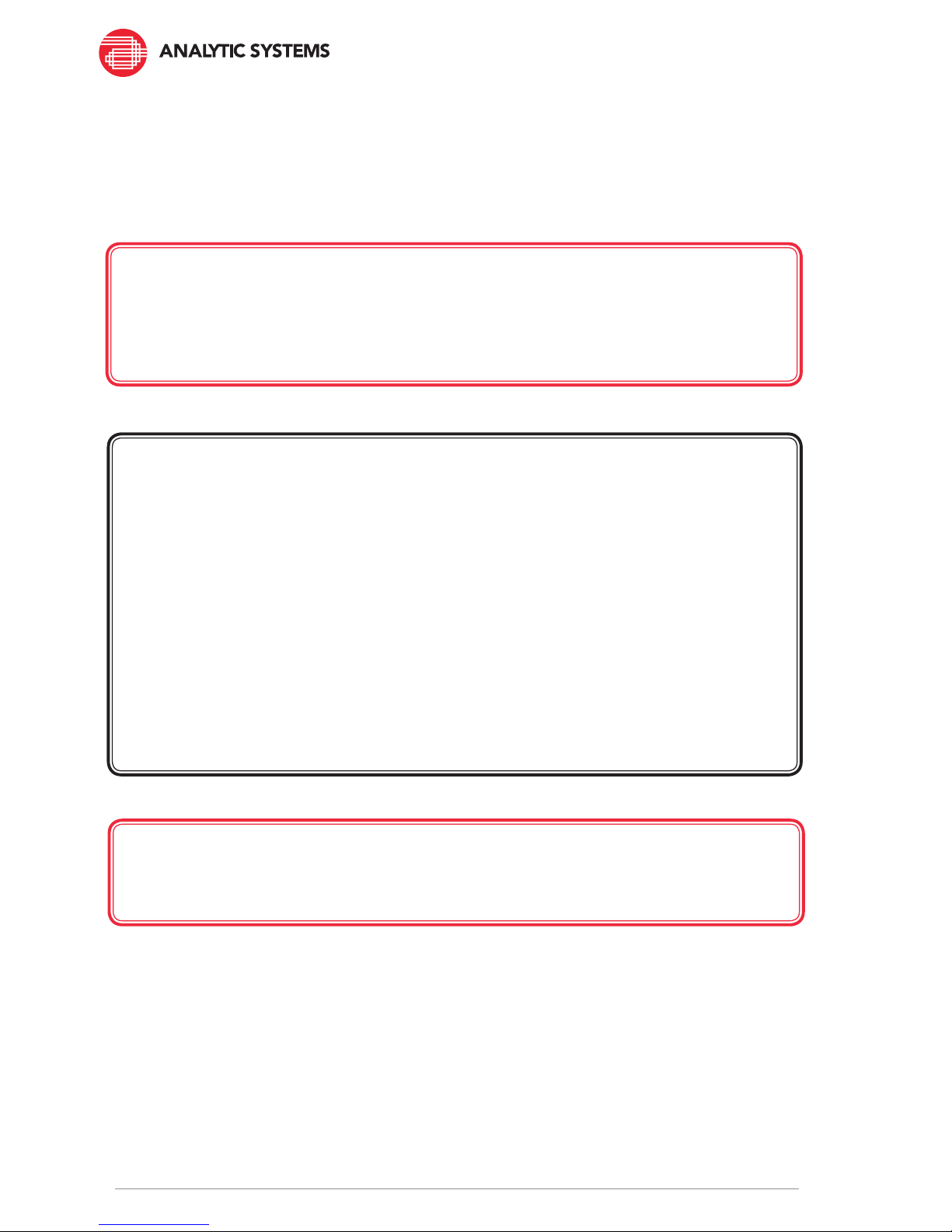
The Power Supply will go through a startup sequence that consists of turning the 6 LEDs
controlled by the computer all Red, then all Green. The Power button will illuminate once the
Power Supply has completely turned on.
If the AC power fails or is disconnected, the Power Supply will resume operation when AC is
restored.
The PWI320 Power Supply is so efcient that is does not need a cooling fan to operate at
maximum performance. However, in a very hot ambient environment the microprocessor
will reduce power output as needed to keep the circuitry operating at a safe and reliable
temperature. In extreme cases, the Power Supply may shut off completely until it cools
sufciently to resume operation.
Operation
INSTALLATION INDICATORS
AC TEMP
25
DEV
75
SVC
FLT
LO V
50
AC PRESENT
PS
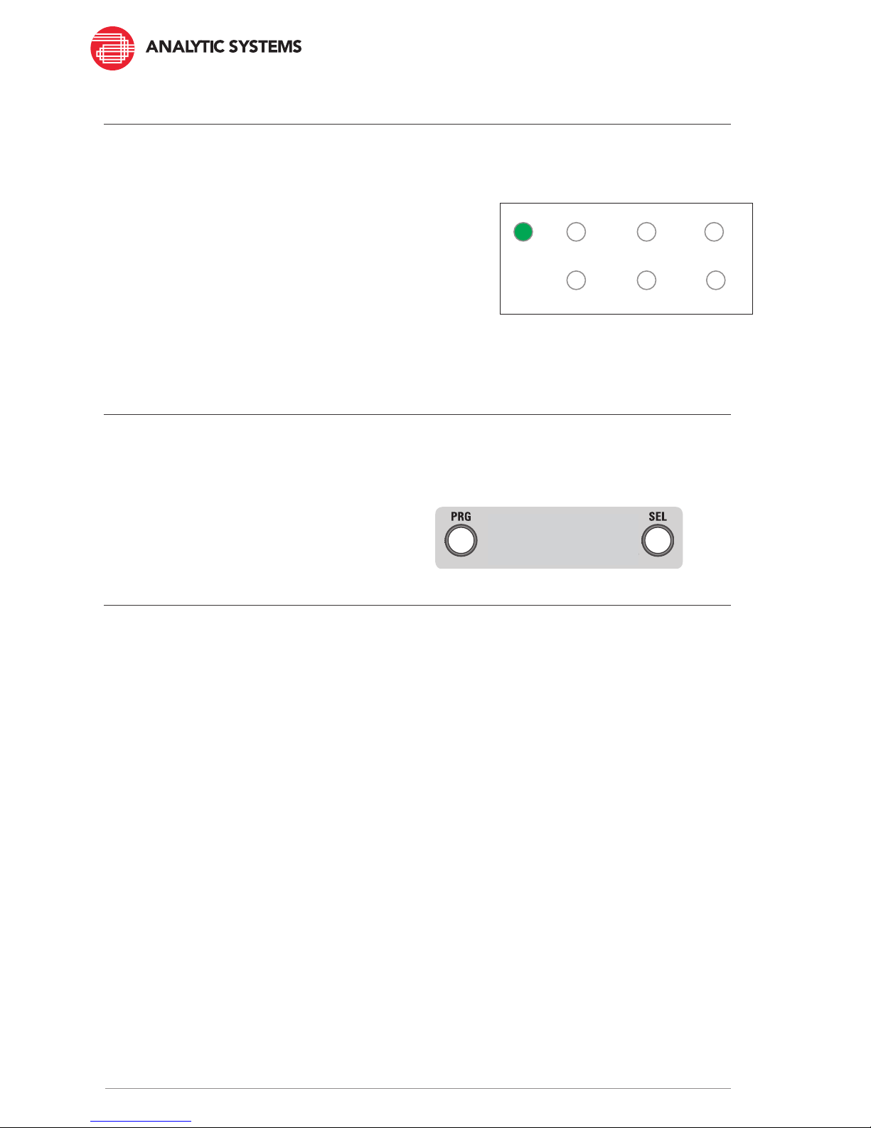
The PRG and SEL buttons on the front panel currently have no function. However, in a future
rmware update they will add the capability to adjust the output voltage over a range from
nominal to +17% (-0V to +2V for a 12V model for example). Subscribe to our newsletter to be
notied when this update becomes available.
Front Panel Adjustments

9
1. The Output Power LEDs will indicate the approximate load percentage the Power Supply
is delivering.
2. The Output Power indicator LEDs will all blink GREEN any time the output current
reaches 100%.
3. The Output Power indicator LEDs will all blink YELLOW any time the output current
reaches 125%. If this happens frequently, the Power Supply is overloaded and the
number of devices connected must be reduced.
4. By use of the Power Wizard PC software, it is possible to customize the output voltage
in Power Supply mode within the working range of the unit (12.0 to 15.0 volts for a 12V
model, scale appropriately for other output voltages). Select the Active Prole and set the
desired voltage in the ‘Float Voltage’ eld and then press ‘Apply Changes’.
POWER SUPPLY INDICATORS BLINKING
CURRENT < 10%
AC TEMP SVCLO V
25 50 75
DEV FLTPS
CURRENT 11 - 39%
AC TEMP SVCLO V
25 50 75
DEV FLTPS
CURRENT 40 - 59%
AC TEMP SVCLO V
25 50 75
DEV FLTPS
CURRENT 60 - 84%
AC TEMP SVCLO V
25 50 75
DEV FLTPS
CURRENT 85 - 99%
AC TEMP SVC
LO V
25 50 75
DEV FLTPS
CURRENT >= 100%
AC TEMP SVC
LO V
25 50 75
DEV FLTPS
CURRENT = 125%
AC TEMP SVCLO V
25 50 75
DEV FLTPS

10
Maintenance
Dry Contact Relay (option)
The Power Supply requires no maintenance other than the occasional wipe down to remove
dust that could reduce its ability to dissipate heat, and carefully blow air through the cooling
vent to remove any dust buildup on it or inside the unit.
The Power Supply can be tted with a 1 amp dry contact relay that can be used to indicate
Power Supply status to a monitoring system. It has both a normally open and normally closed
contact which changes state depending on the presence or absence of charging voltage on
the output of the Power Supply and is independent of the microprocessor. If the Power Supply
is producing voltage on the output, the normally closed contact will be closed and there will
be an electrical connection between NC and COM. If the voltage on the output of the Power
Supply goes to zero, the contact will change state. The Normally Open contact operates
exactly in the reverse of the Normally Closed contact.

11
Troubleshooting
The PWI320 Power Supply is designed to provide years of reliable service. However in the
event that it does not seem to be operating correctly, here are some things you can check.
AC Present LED does not come on.
First make sure any external circuit breaker is ON. Unplug or turn off the external power to the
Power Supply. Plug any other device into the AC receptacle or use a multimeter to make sure
AC is present. Remove the fuse and check for continuity with a multimeter. If the fuse is open,
replace it with the recommended fuse listed on the label and reconnect or turn the power back
on. The AC Present LED should come on. If it does not, then there is an internal failure and the
Power Supply will have to be returned for service.
Output Low Voltage Indication (overload)
If the Power Supply is overloaded and the output voltage drops below 1/2 the nominal voltage
for the unit, the output will cycle on/off until the overload condition is removed.
Power Supply Overtemp
If the Power Supply gets too hot, it will switch to Standby until it cools sufciently to resume
normal operation.
Low Input Volts
If the input voltage drops below the minimum voltage necessary for normal operation, the
Power Supply will show this display. The Power Supply will switch to Standby and wait for
the voltage to recover
Power Supply Failed
If the processor detects a condition that prevents the Power Supply from operating, it will
show this display. Try unplugging and re-plugging the power a couple of times to see if that
clears the problem. If it does not clear the display the Power Supply will have to be returned
for repair. More information on the nature of the fault can be determined by connecting the
Power Supply, using a laptop, and using the Power Wizard program to see if a more detailed
error message is displayed.

12
FAULT INDICATORS
INSUFFICIENT INPUT VOLTAGE
AC TEMP
DEV
SVC
FLT
LO V
PS
25 50 75
BLINKING
OUTPUT OVERLOAD/SHORT CIRCUIT
AC TEMP
DEV
SVC
FLT
LO V
25 50 75
PS
OVER-TEMPERATURE
AC TEMP
DEV
SVC
FLT
LO V
25 50 75
PS
POWER SUPPLY FAILED
POL
AC TEMP
DEV
SVC
FLT
LO V
25 50 75
PS
Abbreviations and denitions
We use a number of abbreviations on the labels to save space. Here are the full words
corresponding to each abbreviation along with common battery Power Supply terms and their
denitions:
ABBREVIATIONS
DEV – Device. Refers to the Power Supply. Used together with the Fault LED to indicate a
problem with the Device.
FLT – Fault. Used to indicate a problem with the battery (BAT) or the device (DEV)
AC – Alternating Current
TEMP – Temperature. Used to indicate that the Device is too hot.
LO V – Low Voltage. Used to indicate that the Input Voltage is too low.
FAIL – Used to indicate that the device needs repair or replacement.
PRG – Program - Button used to initiate the Programming Mode (not used)
SEL – Select – Button used to make choices during front panel programming (not used)
PS – Power Supply

13
This page intentionally left blank

14
This page intentionally left blank

15
Limited Warranty
1. The equipment manufactured by Analytic Systems Ware (1993) Ltd. (the “Warrantor”) is warranted to be free
from defects in workmanship and materials under normal use and service.
2. This warranty is in effect for 5 years from the date of purchase by the end user.
3. Analytic Systems will determine eligibility for warranty from the date of purchase shown on the warranty card
when returned within 30 days, or
a. The date of shipment by Analytic Systems, or
b. The date of manufacture coded in the serial number, or
c. From a copy of the original purchase receipt showing the date of purchase by the user.
4. In case any part of the equipment proves to be defective, the Purchaser should do the following:
a. Prepare a written statement of the nature of the defect to the best of the Purchasers knowledge, and
include the date of purchase, the place of purchase, and the Purchasers name, address and telephone
number.
b. Call Analytic Systems at 800-668-3884 or 604-946-9981 and request a return material authorization
number (RMA).
c. Return the defective part or unit along with the statement at the Purchasers expense to the Warrantor;
Analytic Systems Ware (1993) Ltd., 8128 River Way, Delta, B.C., V4G 1K5, Canada.
5. If upon the Warrantor’s examination the defect proves to be the result of defective material or workmanship,
the equipment will be repaired or replaced at the Warrantor’s option without charge, and returned to the
Purchaser at the Warrantor’s expense by the most economical means. Requests for a different method of return
or special handling will incur additional charges and are the responsibility of the Purchaser.
6. Analytic Systems reserves the right to void the warranty if:
a. Labels, identication marks or serial numbers are removed or altered in any way.
b. Our invoice is unpaid.
c. The defect is the result of misuse, neglect, improper installation, environmental conditions, non-authorized
repair, alteration or accident.
7. No refund of the purchase price will be granted to the Purchaser, unless the Warrantor is unable to remedy the
defect after having a reasonable number of opportchargeries to do so.
8. Only the Warrantor shall perform warranty service. Any attempt to remedy the defect by anyone else shall
render this warranty void.
9. There shall be no warranty for defects or damages caused by faulty installation or hook-up, abuse or misuse of
the equipment including exposure to excessive heat, salt or fresh water spray, or water immersion except for
equipment specically stated to be waterproof.
10. No other express warranty is hereby given and there are no warranties that extend beyond those described
herein. This warranty is expressly in lieu of any other expressed or implied warranties, including any implied
warranty of merchantability, tness for the ordinary purposes for which such goods are used, or tness for a
particular purpose, or any other obligations on the part of the Warrantor or its employees and representatives.
11. There shall be no responsibility or liability whatsoever on the part of the Warrantor or its employees and
representatives for injury to any person or persons, or damage to property, or loss of income or prot, or any
other consequential or resulting damage which may be claimed to have been incurred through the use or sale of
the equipment, including any possible failure of malfunction of the equipment, or part thereof.
12. The Warrantor assumes no liability for incidental or consequential damages of any kind.

8128 River Way, Delta B.C. V4G 1K5 Canada T. 604.946.9981 F. 604.946.9983 TF. 800.668.3884 (US/CANADA)
www.analyticsystems.com
An ISO9001 and AS9100 Registered Company Battery Chargers •Inverters •Power Supplies •Voltage Converters
Table of contents
Other Analytic Systems Power Supply manuals

Analytic Systems
Analytic Systems PWS120 User manual

Analytic Systems
Analytic Systems PWS310 MS User manual

Analytic Systems
Analytic Systems PWS1510MS User manual

Analytic Systems
Analytic Systems IBI Series User manual

Analytic Systems
Analytic Systems PWS150 User manual

Analytic Systems
Analytic Systems FBCS-2K-110-36 User manual

Analytic Systems
Analytic Systems PWS1005W User manual

Analytic Systems
Analytic Systems PWS610 Series User manual

Analytic Systems
Analytic Systems PWS1000R series User manual

Analytic Systems
Analytic Systems PWS1505 User manual