ANDERSON-NEGELE IZMSA User manual

SENSORS FOR FOOD AND LIFE SCIENCES.
30049 / 1.0 / 2023-03-30 / SD-MH / EN-EU
Operating Manual
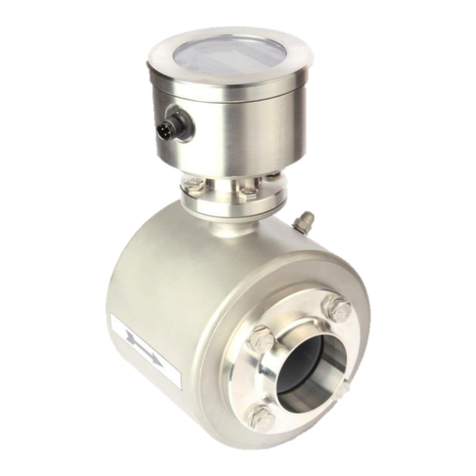
Electro-Inductive Flow Meter
IZMSA

IZMSA Flow Meter
- 2 -

IZMSA Flow Meter
- 3 -
Table of Contents
1. General Description.................................................................................................9
1.1. Preface ....................................................................................................................9
1.2. Construction...........................................................................................................9
1.3. Function ..................................................................................................................9
2. Safety Instructions...................................................................................................9
2.1. General Remarks....................................................................................................9
2.2. Intended Application ............................................................................................10
2.3. Possible Misuse....................................................................................................10
2.4. General Safety Instructions .................................................................................11
2.5. Special Safety Instructions and Contrivances....................................................12
3. Transport ................................................................................................................13
3.1. General Remarks..................................................................................................13
3.2. Special Remarks...................................................................................................13
4. Separate design .....................................................................................................14
5. Compact design .....................................................................................................14
6. Arrangement...........................................................................................................15
6.1. Conditions for the Transmitter ............................................................................15
6.2. Fitting Position......................................................................................................15
6.3. SUGGESTIONS FOR MOUNTING.........................................................................17
6.4. Inlet and Outlet Pipe Sections .............................................................................18
6.5. Conductivity Conditions ......................................................................................18
6.6. Interference Fields................................................................................................18
6.7. Earthing/Grounding Conditions...........................................................................18
7. Meter Tube Lining ..................................................................................................19
8. Flow Direction ........................................................................................................19
9. Operating Conditions of the Converter................................................................19
10. Prevention of Condensation .................................................................................19
11. Cable lengths for the separated transmitter version ..........................................20
12. Installation..............................................................................................................20
12.1. Installation Instructions for the Transmitter.......................................................20
12.2. Installation of the Converter ................................................................................20
12.3. Installation of the Electric Supply Voltage..........................................................21
13. Use as directed: .....................................................................................................21
14. Staff Qualification ..................................................................................................21

IZMSA Flow Meter
- 4 -
14.1. Connection of the Transmitter.............................................................................22
14.2. Brief Instructions..................................................................................................23
14.3. Electrical Connection of Peripherals...................................................................24
14.4. Connection of a Quantity Counter.......................................................................25
14.5. Connection of a Digital Indicator.........................................................................26
14.6. Analog output .......................................................................................................26
15. Commissioning ......................................................................................................27
15.1. General Remarks..................................................................................................27
15.1.1. Safety Measures for the Commissioning Work..........................................27
15.2. Check List before the Initial Start-up...................................................................28
15.3. Basic Settings upon the Commissioning............................................................29
16. Structure and Operating Elements.......................................................................29
16.1. LED array...............................................................................................................31
16.2. Transmitter connection in the separated version ..............................................32
17. Calibration Switch..................................................................................................32
18. ABORT Key ............................................................................................................33
19. Calibration Data Storage
„MEMbox “...................................................................33
19.1. Display Unit...........................................................................................................33
19.2. ZERO key...............................................................................................................34
20. Converter without Display Unit.............................................................................34
21. Flow Direction ........................................................................................................34
21.1. Change of the Flow Direction ..............................................................................35
21.2. Zero Adjustment (“ZERO Adjust”).......................................................................35
22. Metering Operation with Digital and Analog Outputs.........................................37
22.1. Digital Outputs IMP1 –IMP3.................................................................................37
22.2. Output "OUT"........................................................................................................37
22.3. Analog Output.......................................................................................................38
22.4. Allocation of the Digital Inputs ............................................................................38
23. Measurement with Empty Meter Tube..................................................................38
23.1. Internal "EMPTY Pipe Detection".........................................................................38
23.2. External "EMPTY Pipe Detection.........................................................................38
24. Measurement at Low Conductivities....................................................................39
25. Measurement at Pulsating Flow ...........................................................................39
26. Operation................................................................................................................40
26.1. Display Operation in the Metering Mode.............................................................40
27. Main Counter..........................................................................................................42
27.1. Daily Quantity Counter.........................................................................................42
27.2. Totalizing Counter................................................................................................42
28. Reset of Error Messages.......................................................................................43

IZMSA Flow Meter
- 5 -
28.1. Reset of the Running Counter .............................................................................43
29. Parameterization ....................................................................................................43
29.1. Protection of the Parameters against Unauthorized Modification ....................44
30. Function 98.............................................................................................................44
30.1. “CAL”Position......................................................................................................44
31. How to Modify the Parameters..............................................................................45
31.1. Overview of the Parameters.................................................................................47
31.1.1. Device Parameters (Menu 02) ..................................................................49
31.2. Output Mode .........................................................................................................51
31.3. Input/Output Parameters (Menu 03) ....................................................................53
31.4. Display Parameters (menu 04).............................................................................54
32. Structure of the Data Memory...............................................................................55
32.1. Determination of Parameters and Calibration Data............................................55
32.2. Calibration Factor "m spe"...................................................................................55
32.3. Positive Flow Factor "p spe" ...............................................................................56
32.4. Negative Flow Factor "n spe"..............................................................................56
32.5. Dimensioning Factor "m dim" .............................................................................56
32.6. Fine Adaptation by “b spe”..................................................................................57
33. Help in Case of Malfunction..................................................................................57
33.1. Error Messages.....................................................................................................57
34. Typical Effects or Possible Malfunctions ............................................................59
34.1. The Display Shows “warning 901“......................................................................59
34.2. If Existing Flow is Not Displayed:........................................................................59
34.3. The Pulse Transmission is Disturbed Although Flow is Displayed..................60
34.4. No Analog Signal Available..................................................................................60
34.5. Strong Fluctuations of Measured Values............................................................61
34.6. Reset of Error Messages......................................................................................61
34.7. Displayed Messages.............................................................................................62
35. List of Possible Key Functions.............................................................................63
36. Output Simulation..................................................................................................63
37. Hardware Test ........................................................................................................64
38. Transmitter Test.....................................................................................................65
38.1. Insulation Test ......................................................................................................65
38.2. Symmetry Test......................................................................................................65
38.3. Visual Check.........................................................................................................66
39. Maintenance ...........................................................................................................66
39.1. Upkeep ..................................................................................................................66
39.2. Safety Precautions for Maintenance ...................................................................67
39.3. Preventive Maintenance Steps ............................................................................67
40. Repairs....................................................................................................................68
40.1. Sending in the Flow Meter to the Manufacturer..................................................68
IZMSA Flow Meter
- 6 -
40.2. Repair Work ..........................................................................................................69
40.3. Replacement of the Fuse for Feeble Currents....................................................69
40.4. Replacement of the Main Board ..........................................................................69
40.5. Status upon the Delivery of a Spare Main Board................................................69
40.6. Replacement of the Power Supply Unit...............................................................70
40.7. Replacement of the Storage Battery ...................................................................70
40.8. Replacement of the Housing Cover.....................................................................70
40.9. Replacement of the Transmitter ..........................................................................70
40.10. Spare Parts to be Kept Available on Stock.........................................................71
41. Decommissioning ..................................................................................................71
41.1. Temporary Decommissioning..............................................................................71
41.2. Final Decommissioning / Disposal......................................................................71
42. Spare parts .............................................................................................................72
43. Description T0 Version..........................................................................................73
44. Electrical connection.............................................................................................73
44.1. Intended use: ........................................................................................................73
44.2. Connecting the transmitter..................................................................................73
44.3. Connection of a temperature sensor Pt 100 .......................................................74
45. General remarks - T0 Version ...............................................................................75
45.1. Operating elements ..............................................................................................75
45.2. "ZERO"-Taste........................................................................................................75
45.3. Switching on the supply voltage .........................................................................76
46. Measuring mode ....................................................................................................76
46.1. Operation...............................................................................................................76
46.2. Zero position of the volume counters.................................................................76
46.3. Serial interface......................................................................................................77
46.4. RS232 connection.................................................................................................77
46.5. RS232 parameter ..................................................................................................78
46.6. Scope of data via the serial interface..................................................................78
46.7. Implementation of the protocol of the serial interface.......................................78
46.8. Types of data blocks ............................................................................................79
47. Flow direction.........................................................................................................80
47.1. Flow in "+" direction.............................................................................................80
47.2. Flow in "-" direction..............................................................................................80
48. Calibration parameters (menu 05) ........................................................................81
48.1. Date/time (menu 08)..............................................................................................82
49. If the existing flow is not displayed: ....................................................................82
49.1. Considerable fluctuations of the measured value..............................................82
50. Hardware-Test........................................................................................................83
51. How to correct the temperature display ..............................................................83
52. Structure and denomination of the device - Transmitter ...................................86

IZMSA Flow Meter
- 7 -
52.1. Transmitter in separated design..........................................................................86
52.2. Measuring ranges and error limits ......................................................................86
53. Intended use...........................................................................................................86
54. Dimensions and weight.........................................................................................87
54.1. Transmitter in separated design..........................................................................87
54.1.1. Dimensions of the process connections....................................................87
55. Conditions required for the transmitter ...............................................................90
55.1. Parts of air and gas ..............................................................................................90
55.2. Solid parts.............................................................................................................90
55.3. Conductivity conditions.......................................................................................90
55.4. Meter tube lining...................................................................................................90
55.5. Flow direction .......................................................................................................90
56. Cable lengths for the separated transmitter version ..........................................90
57. Welding work..........................................................................................................91
57.1. Wire end ferrule ....................................................................................................91
58. Installation..............................................................................................................92
58.1. Installation instructions for the transmitter........................................................92
58.2. Connection of the transmitter in separated design............................................93
58.2.1. Function:...................................................................................................93
58.2.2. Connection scheme for the separated design ...........................................93
59. Connection transmitter .........................................................................................94
60. Advice for starting-up the Flow Tube...................................................................95
61. MEMBOX.................................................................................................................96
62. Measuring accuracy ..............................................................................................96
63. Visual check ...........................................................................................................96
64. Maintenance ...........................................................................................................96
64.1. Safety instructions for maintenance work..........................................................96
65. Quantity Preselection Functions ..........................................................................96
65.1. General Description..............................................................................................96
66. Electrical Connection ............................................................................................97
66.1. Operation...............................................................................................................98
67. Keg mode of Operation (external Control) ("preset mode 1") .........................100
68. Manual drum selection ("preset mode 2") .........................................................102
69. Quantity preselection via the Profibus (“preset mode 4”) ...............................103
69.1. Keg mode of operation via the Profibus (“preset mode 5”).............................103

IZMSA Flow Meter
- 8 -
70. Drum Statistics.....................................................................................................105
71. Quantity Preselection Parameters......................................................................106
72. Functions of the Quantity Preselection Parameters.........................................107
72.1. Setting and Optimization of the Preselection Parameter.................................107
73. Error messages....................................................................................................108
74. Additional Information.........................................................................................109

IZMSA Flow Meter
- 9 -
1. General Description
1.1. Preface
This documentation includes some information protected by copyright. It is not allowed to be
photocopied, copied, duplicated, translated, or recorded on data carriers (neither completely nor in
extracts).
This instruction manual should be carefully read before the operation of the equipment is started.
It must be deposited in the direct vicinity of the device described, easily accessible to all persons
concerned.
It is necessary to strictly observe and follow the safety instructions.
Negele Messtechnik GmbH cannot assume any liability or legal responsibility for operating errors
caused by the non-observance of these directions.
1.2. Construction
This instruction manual is applicable to the following versions of the electro-magnetic flow meters
type IZMSA
1. Separated design, consisting of:
a. transmitter Flow Tube
b. converter in field housing
c. connection cable for coil supply and electrode signal
2. Integrated design, consisting of:
The transmitter, which is completely wired to the converter, i.e., it forms one single metering
unit.
1.3. Function
The measuring instrument is suitable for metering the flow as well as the quantity of conductive
liquids.
The electromagnetic flow meters of the type IZMSA determine the flow and the volume of liquids
at a high precision.
IZMSA-C, IZMSA-R type converters are microprocessor-controlled devices. They supply the
transmitters with a switched and controlled coil current.
The signal generated at the electrodes is amplified and conditioned in the converter and
processed in the internal measurement registers as a flow and volume information.
Those values can be indicated on the display unit (option).
In addition, some volume pulses (e.g., 1 pulse per liter) are generated and a flow signal (of
0/4...20 mA for a flow of 0...100%) is released.
Usually, the device is delivered with standard settings, i.e., all you must do is to connect the
transmitter, the supply voltage, and possibly existing peripheral devices (such as: digital display,
pulse counter).
2. Safety Instructions
Due to the great variety of possible operating conditions this instruction manual can consider the
general application only.
Special cases such as extraordinary ambient conditions or special safety instructions require
coordination with the manufacturer.
2.1. General Remarks
Special Diligence of the User

IZMSA Flow Meter
- 10 -
This measuring instrument has been designed and built in consideration of a risk analysis and after
a careful choice of the harmonized standards and further technical specifications to be kept. It
corresponds to the state of the art and offers an optimum safety.
In practical use, however, that degree of safety can only be obtained when all measures required
in this respect will be really taken. It belongs to the diligence of the user of the flow meter to plan
such measures and to check and survey if they are really performed.
The user must ensure that:
- the measuring instrument is only used for the intended application as directed (also see the
following chapter „Intended Application “)
- the measuring instrument is operated in a perfect and functioning condition and that especially
the safety contrivances are regularly checked for their operability
- the personal protective equipment required for the operating, maintenance, and repair staff is
kept available and really used
- the complete instruction manual in a legible condition is permanently available at the location of
the measuring instrument
- the system is operated, serviced, andrepaired by sufficiently qualified andauthorized personnel
only
- the personnel concerned is regularly trained for all applicable questions of the protection of
labour and environment and familiarized with the instruction manual and especially the safety
precautions included therein.
- all the safety and warning instructions attached to the measuring instrument are not removed
and kept in a legible condition.
In case of any problems that he cannot remove on his own, the user of the system should contact
the service department of Negele Messtechnik GmbH.
2.2. Intended Application
The measuring instrument may only be used for the application that it has been designed,
dimensioned, and built for:
- for the connection to an earthed monophase network or a direct current network (see type
plate).
- in industrial areas according to EN 61000-6-2/4 for reasons of EMC.
The intended purpose of the electromagnetic flow meter is the measurement of conductive liquids
in the food processing industry and in the cosmetic, pharmaceutical, and chemical industries.
This flow meter is not suitable for the measurement of hazardous, explosive, and combustible
liquids of PED group 1.
Any modifications to the system that might have an influence on the function and the safety contrivances
of the system are only allowed to be carried out by the engineering specialists or authorized persons of
Negele Messtechnik GmbH.
2.3. Possible Misuse
Any utilisation being in contradiction to the above-mentioned application means an inadmissible
misuse of the measuring instrument! In such a case Negele Messtechnik GmbH does not assume
any responsibility for the safety.

IZMSA Flow Meter
- 11 -
Negele Messtechnik GmbH must be contacted before the flow meter will be used for any different
application, and after a careful investigation of all facts Negele Messtechnik GmbH could possibly
release the flow meter for the intended new application.
2.4. General Safety Instructions
These safety instructions must be strictly observed in order:
•to not endanger the safety of persons and environment,
•to avoid any damages to the measuring instrument,
•to prevent any faulty batches upon the production.
The electrical connection may only be carried out by persons who have got the necessary expert
knowledge (e.g., trained electrical fitters or persons instructed in electrical engineering) and the
necessary authorization from the user.
Warning against
dangerous electrical voltage!
Unauthorized persons are not allowed to.
open a housing bearing the above symbol!
The wiring of the voltage supply and the inputs and outputs of the control circuits must be carried
out professionally in consideration of the up-to-date state of the art. Also refer to chapter 4
“Installation”/” Electrical Connection”.
In particular, the following directives must be observed:
•Safety instructions
•Electrical connection data
1. All persons who are involved in the installation, commissioning, operation, service, and
maintenance of the flow meter must be qualified accordingly.
2. This instruction manual must be strictly observed. The user of the flow meter must guarantee that
the personnel concerned has read and fully understood the instruction manual.
3. All kinds of work must be done with utmost care and may be carried out by accordingly authorized
and trained personnel only.
4. The instruction manual must be available close to the flow meter, easily accessible to the operating
staff.
5. Before any cleaning, conversion, service, and maintenance work is started, the measuring
instrument must be switched off and separated from the mains supply. The main switch must be
secured against unauthorized switching on.
6. Before any service and maintenance work is started, the system must be discharged and flushed
with water. If the measuring instrument must be removedfrom the pipe system, all pipelines will have
to be previously emptied by application of some appropriate emptying and shut-off measures.
7. Never remove or put out of action any safety contrivances by modifications to the device.

IZMSA Flow Meter
- 12 -
8. Do not touch any parts flown through by the medium while the measuring instrument is cleaned.
Otherwise, you run the risk of getting burnt!
9. To minimize the danger of injury, the working area of the operator must allow sufficiently free space.
10. The technical data according to the instruction manual, type plate and, if available, the performance
specification must be considered.
If damages are caused due to an inexpert performance of work any warranty claims will extinguish.
Dangers not resulting from the functionality of the device, but from the ambient and
operating conditions prevailing at the place of application, must be referred to by
appropriate instructions to the operators and by the attachment of some danger
signs!
The user of the flow meter/system is exclusively responsible for the compliance with these
instructions!
2.5. Special Safety Instructions and Contrivances
The following dangers could be directly or indirectly caused by the measuring instrument type IZMSA
during operation or commissioning:
•Electrical shock in case of an inappropriate opening of the electronic housing.
•Burns by touching hot pipe sections.
•Scalds and/or chemical burns by hot liquids or gas coming out through leaking flange connections
or because of an inexpert opening of the pipe system.
The following safety contrivances are available for flow meters type IZMSA:
•Earthing/grounding of the supply voltage
•Protection against accidental contact of the plug-in bridges on the power supply unit
Explanation of the Safety Symbols Used in this Manual
Hot caustic solution can cause
serious chemical burns
Attention
Beware of
hazardous
electric tension
Beware of
hand injuries!
Beware of
hot surfaces!

IZMSA Flow Meter
- 13 -
Es besteht erhöhte
Rutschgefahr im
Nassbereich!
3. Transport
3.1. General Remarks
The following points must be strictly observed to avoid any damages to the measuring instrument
or very serious injuries during the transport of the device:
Transport work is only allowed to be carried out:
-by accordingly qualified and authorized persons,
-by the aid of appropriate load suspension and fastening devices,
-when any risk upon lifting and/or conveying the device can be fully
excluded.
The packing of the measuring instruments is subject to the following labelling:
Fragile goods
Keep dry!
Check the added packing list before you will start opening the packing!
Compare by means of the packing list if all parts are available or not!
Treat sensitive parts with special care!
Please do not fail to dispose of the packing material according to the appropriate regulations.
3.2. Special Remarks
The pipe ends of the transmitter are provided with protective caps to protect the plastic liner of
the meter tube against damages.
Do not remove the protective caps until the installation of the transmitter.
Beware of
hot liquids and
steams
Beware of media
detrimental to health or
irritating substances!
Beware of an increased
risk of skidding in wet
areas!
Electrostatically
endangered system
component
Electronic scrap

IZMSA Flow Meter
Transport
- 14 -
Unless any protective caps are available during transport, take care that no sharp-edged objects
will be pressed against the plastic surfaces of the transmitter.
Re-attach the protective caps before each transport!
When removing the packaging film, see to it that no components of the device (such as display or
keyboard) are damaged or destroyed.
4. Separate design
5. Compact design
DN
B
[mm]
D
[mm]
H1
[mm]
H2
[mm]
Weight
[kg]
10
104
90
110
201
4
15
104
90
110
201
4
25
104
90
110
201
4
32
104
105
125
216
5
40
104
105
125
216
5
50
104
130
150
241
6
65
160 *)
130
150
241
7
80
160 *)
155
175
266
10
100
200 *)
170
190
281
12
125
250 *)
220
240
331
26
150
300 *)
220
240
331
29
DN
B
[mm]
D
[mm]
H1
[mm]
H
[mm]
Weight
[kg]
10
104
90
110
250
6
15
104
90
110
250
6
25
104
90
110
250
6
32
104
105
125
265
7
40
104
105
125
265
7
50
104
130
150
290
8
65
160
130
150
290
9
80
160
155
175
315
12
100
200
170
190
330
14
125
250
220
240
380
29
150
300
220
240
380
31

IZMSA Flow Meter
Arrangement
- 15 -
6. Arrangement
6.1. Conditions for the Transmitter
The installation of the measuring instrument depends on the delivered version. In any case the
transmitter must be installed in the product line and the converter must be supplied by electric
tension.
After the installation of the measuring instrument, you should in any rate ensure an optimum
earthing/grounding, if some welding work must be performed.
Crossflows should be absolutely avoided, as they could cause some damages to the electronic
part.
To protect the transmitter against damages,
select the place of installation so that:
•the process pressure is always kept below the admissible operating pressure.
•the product temperature is always kept below the admissible temperature.
•the transmitter is not cleaned by means of hot steam.
•the transmitter is mechanically levelled out (e.g., to avoid vibration)
•the transmitter is not operated at negative pressure.
•the meter tube can be emptied in case of the danger of frost.
•integrated devices with built-in display are not permanently subject to direct insolation.
•the measuring instrument is not arranged straight above a gully or sink hole.
•the connection housing is not permanently exposed to drip water.
6.2. Fitting Position
Due to the principle described, the fitting position (to a certain extent) can be selected any way
desired. The basic condition for accurate measuring results is, however, a full and gas-free meter
tube.
If possible, the electrode axis should be arranged horizontally, to avoid a deposition of gas bubbles
or solid particles on the surface of the electrodes. Therefore, a slightly ascending pipeline is
advisable, preferably with a deaerating possibility at its highest position.
The fitting position should be chosen in such a way that a good readability and handling of the
operating unit is guaranteed.
The pipelines within the inlet and outlet pipe sections must not show any unevenness, e.g., welding
beads.
Caution

IZMSA Flow Meter
Arrangement
- 16 -
max. 45°

IZMSA Flow Meter
Arrangement
- 17 -
6.3. SUGGESTIONS FOR MOUNTING
Wrong
Highest point of the pipeline. Gas bubbles accumulate in the
transmitter - measuring error!
Correct
Preferred mounting position:
Rising pipeline and horizontal pipe section before an ascending
pipeline.
Wrong
Descending pipe:
At the end of the conveyance of the metered product the pipe runs
empty - measuring errors!
Correct
In case of a horizontal pipe conduct the mounting, position is placed
in slowly increasing sections of the pipe.
Correct
For free inlet or outlet provide drain. Transmitter is permanently filled
with liquid as demanded.
Descendingpipelinesof alength of morethan 5m mustbe equipped
with a deaeration valve after the flow meter.
Long lines afterthe flow meter always must be equipped with a shut-
off device. If it is placed before the flow meter, therewill be a vacuum
in the metering pipe when shutting off due to the big kinetic energy
in the liquid column. This will damage the lining of the tube.
Do not place the flow meter on the suction side of the pump.
Danger of negative pressure!
Keep the recommended inlet and outlet sections.
Avoid curvatures of space before the electromagnetic flow meter.
freier Auslauf = free outlet

IZMSA Flow Meter
Arrangement
- 18 -
6.4. Inlet and Outlet Pipe Sections
For the installation of electromagnetic transmitters DIN 1944 recommends an inlet pipe section of
5 x DN and, accordingly, an outlet pipe section of 2 x DN in case of an undisturbed flow. For an
irregular flow (e.g., distorted rotational flow profile) the inlet and outlet pipe sections must be
extended accordingly or a rectifying device for the flow must be installed to guarantee the specified
measuring accuracy.
6.5. Conductivity Conditions
The minimum conductivity of the product may not fall below 5 µS/cm.
A count suppressor for empty meter tubes belongs to the standard equipment of the converter.
That function will have to be switched off at conductivities below 50 µS/cm.
6.6. Interference Fields
Straight at the transmitter no masses of iron or strong permanent or electromagnetic fields may
exist which could influence the defined exciting magnetic field, thus falsifying the signal.
6.7. Earthing/Grounding Conditions
A perfect earthing/grounding of the transmitter is an essential requirement for a reliable and
accurate measurement.
“Inductive measuring method” means that the metered liquid itself acts as an electric conductor,
i.e., a correct and careful earthing/grounding ensures that no additional potentials will falsify the
extremely low metering signal.
For that reason, the earthing/grounding resistance must be smaller than 10 ohms. The
earth/ground wire used must not transfer any interference voltages, i.e., no other electric devices
may be connected to that line.
In case of the separated design, the earthing/grounding between transmitter and converter is
achieved by means of the shielding braid of the electrode cables and the coil supply cables with
the metal cable gland provided for that purpose.
Transmitter with threaded milk pipe fitting:
Assembly into a metal pipeline without lining. Through the pipe the
threaded milk pipe fittings form the earth/ground connection to the
liquid.
Transmitter with flange connection, mounted into a metal pipeline
without internal coat or insulating lining:
There is no need to provide any earth/ground wires to the mating
flanges, if these are made of stainless steel and not lacquered.
Transmitter with flange connection, mounted into a plastic pipeline
or a pipeline with insulated internal lining:
Some additional earthing/grounding rings are required in the inlet
and the outlet of the transmitter. Those rings form the connection to
the liquid.

IZMSA Flow Meter
Arrangement
- 19 -
7. Meter Tube Lining
A damaged lining will always cause measuring errors or even a failure of the flow meter.
8. Flow Direction
The arrow on the type of plate shows the calibrated flow direction from MINUS to PLUS.
Inflow from the right to the
left results in a negative
flow indication
Inflow from the left to the
right results in a positive
flow indication
In principle, the flow meter can measure in both directions.
Provided that the recommended inlet and outlet conditions are kept, the accuracy of the
measurement in both directions is only slightly different.
The effect of the internal measuring registers and of the volume and flow signals depends on the
selected parameterization.
9. Operating Conditions of the Converter
To protect the converter against damages, always select the place of installation
so that:
•the ambient temperature is within a range from –20...+55 °C.
•the field housing is fastened free from any mechanical distortion.
•no moisture can enter the field housing through the cable glands.
•the housing is not permanently strained by drip water.
•Devices with built-in display are not permanently subject to direct insolation.
10. Prevention of Condensation
If the measuring instruments are permanently subject to very high air moisture at varying ambient or
product temperatures (e.g., hot cleaning), humidity can develop in the connection housing of the
transmitter or even of the converter due to occurring negative pressure.
The most efficient remedy recommended against that effect is a pressurization of the housings with dry air
of approximately 0.2 bars or a forced-air ventilation of the housings with dry air.
Caution
Dry
air

IZMSA Flow Meter
Arrangement
- 20 -
11. Cable lengths for the separated transmitter version
The transmitter is integrated straight into the pipeline.
For reasons of EMC, the transmitter must be installed at a possibly small distance from the
converter, i.e., the connection cable should be kept as short as possible.
The standard coil and electrode cables delivered are destined to cover 5 m each.
The following conditions must be considered for larger distances:
a. The cables must be laid into a separate cable duct.
b. Laying the cables near to frequency converters or motors must be absolutely avoided.
c. The maximum distance between transmitter and converter depends on the conductivity of the
product. The following approximate values are recommended:
Conductivity
Maximum cable length
15 -50 µS/cm
5 m
50 - 200 µS/cm
20 m
> 200 µS/cm
50 m
d. The shielded cables prescribed by the manufacturer must be used.
e. The shielding must be connected to the transmitter and the converter.
12. Installation
12.1. Installation Instructions for the Transmitter
Consider that the threaded fittings, clamps, or flanges are perfectly tightened.
Otherwise, hot, or caustic solutions or gasses could come out of the gaps or
clearances.
Pay attention to the fact that the threaded fittings, clamps, or flanges are perfectly
tightened! Otherwise, hot, or caustic solutions or gasses could come out of the gaps
and clearances.
CAUTION! The bead is neither allowed to be damaged nor separated!
Do not omit to insert the seals into the screwed counter fittings!
In case of leaky pipe connections, you should not neglect to check the seal. Never overtighten the
screwed pipe connections!
12.2. Installation of the Converter
For the separated design the field housing is typically delivered for wall mounting.
In case of the integrated design the converter is installed straight into the pipeline.
Cable glands always must point downwards.
When installing the flow meter pay special attention to the fact that no moisture (e.g., by drip water
or splash water) can get onto the electronic board.
Caution
Table of contents
Other ANDERSON-NEGELE Measuring Instrument manuals

ANDERSON-NEGELE
ANDERSON-NEGELE IZMAG User manual

ANDERSON-NEGELE
ANDERSON-NEGELE FMQ User manual

ANDERSON-NEGELE
ANDERSON-NEGELE Load Stand II User manual

ANDERSON-NEGELE
ANDERSON-NEGELE ILM-4R User manual

ANDERSON-NEGELE
ANDERSON-NEGELE ITM-51 User manual

ANDERSON-NEGELE
ANDERSON-NEGELE ILM-4 User manual

ANDERSON-NEGELE
ANDERSON-NEGELE ITM-51R User manual

ANDERSON-NEGELE
ANDERSON-NEGELE FMQ User manual