Stephan Artec Operating instructions
Artec / Portec
Anaesthesia Apparatus
Service Instructions
02
N
0
2
0,2
STEPHAN
2
O
4
8
7
6
2
1
2
5
4
2
3
O
N
2
01
1 2
10
11
9
12
2
10
8
6
OFF
A
N
ESTHESIE GME 2
2
0
N
0
2

Preface
2 SA-103-0109V1.3-HAO-GB ©F. Stephan GmbH
Please carefully read each step of the procedure that is to be carried out
before beginning the servicing of the unit. Always use the correct tools
and the indicated measuring instruments. Any non-compliance with the
instructions and/or recommendation found in this technical
documentation can lead to a malfunctioning of the equipment or damage
to it.
Use only original replacement parts as supplied by F. STEPHAN GMBH,
and that are listed in the Replacement Parts List.
This technical documentation is not to be used in place of the operating
instructions. Each operation and handling of the equipment requires exact
knowledge and observance of the operating instructions. This equipment
is only to be used for the stipulated application.
Service Instruction
F. Stephan GmbH
- Medizintechnik -
Kirchstrasse 19
56412 Gackenbach, Germany
Subject to technical changes.
Status: January 2009
Version: V1.3

®
Table of Contents
©F. Stephan GmbH SA-103-0109V1.3-HAO-GB 3
Table of Contents
Table of Contents.......................................................................................3
1General Information...........................................................................7
1.1 Equipment designation and manufacturer ...............................7
1.2 Technical safety inspections....................................................7
1.3 Maintenance.............................................................................7
1.4 Warranty..................................................................................8
2Connections on part of the supply system .........................................9
2.1 Check of the plug-in gas couplings O2, N2O, AIR for:............9
2.2 Check of the gas connection tubes O2, N2O, AIR, for:............9
2.3 Check of the screw joints of the connecting threads O2, N2O,
AIR for:....................................................................................9
2.4 Check of the female connecting threads O2, N2O, AIR for:..10
3Description of Design and Performance..........................................11
3.1 Gas-mixing-unit 2 and 3 (GME 2/GME 3)............................11
3.1.1 O2-Flush ....................................................................12
3.1.2 AIR / N2O-Change-Over...........................................12
3.1.3 Nitrous Oxide Blocking.............................................13
4Vaporizer, Vaporizer holding device...............................................15
4.1 Vaporizer...............................................................................15
4.2 Vaporizer holding device.......................................................15
5Cylinder Supply Unit.......................................................................17
6Circle System...................................................................................19
6.1 Design and Description of Performance................................19
6.1.1 CL (closed)................................................................20
6.1.2 Pressure Range from 5mbar to 50mbar.....................20
6.1.3 Spontaneous Respiration...........................................20
6.1.4 VOL (volume-controlled ventilation) .......................20
6.1.5 Circle System ............................................................21
7Performance Test.............................................................................23
7.1 Execution of the Test.............................................................23
7.2 O2-Flush.................................................................................24
7.3 Air / N2O-Change Over (Basic setting).................................24
7.3.1 Execution of the Test.................................................24

Table of Contents
4 SA-103-0109V1.3-HAO-GB ©F. Stephan GmbH
7.4 Check of types of gas and test of the safety devices..............25
7.4.1 Execution of the Test.................................................25
7.4.2 Proportioning Valves.................................................25
7.5 Tightness of the Circle System..............................................26
7.5.1 Basic setting ..............................................................26
7.5.2 Execution of the Test.................................................27
7.6 Test of the pressure-regulating valve.....................................27
7.6.1 Basic setting ..............................................................28
7.6.2 Execution of the Test.................................................28
7.7 Test of inspiration-and expiration valve................................29
7.7.1 Basic setting ..............................................................29
7.7.2 Execution of the Test.................................................29
8Diagram of pneumatic control system.............................................31
8.1 Pneumatic control system O2/ N2O / AIR.............................31
8.2 Pneumatic control system O2/ N2O.......................................32
9Troubleshooting Guide ....................................................................33
9.1 Portec.....................................................................................33
9.2 Circle System.........................................................................34
10 Technical Data.................................................................................35
10.1 Dimensions............................................................................35
10.2 Type of gas connections ........................................................35
10.3 Measuring range of the flowmeter tubes...............................36
10.4 Accuracy of the flowmeter tubes...........................................36
10.5 O2-Failure alarm ....................................................................36
10.6 Technical Data Circle System ...............................................36
11 List of spare parts.............................................................................37
11.1 Circle system .........................................................................37
11.1.1 Semi-annual servicing circle system.........................38
11.2 Absorber ................................................................................39
11.2.1 Semi-annual servicing Absorber...............................39
11.3 Expiration valve.....................................................................40
11.3.1 Semi-annual servicing expiration valve....................40
11.4 Inspiration valve....................................................................41
11.4.1 Semi-annual servicing inspiration valve ...................42
11.5 Artec / Portec.........................................................................42
11.6 Vaporizer...............................................................................44

®
Table of Contents
©F. Stephan GmbH SA-103-0109V1.3-HAO-GB 5
11.7 Flowmeter tube......................................................................45
11.8 Spindle46
11.9 Instruction Flowmeter tube....................................................48
12 Measuring of electrical power leakage ............................................49
13 Servicing..........................................................................................51
14 Test Certificate.................................................................................53
15 Acceptance of the apparatus ............................................................55
16 Index of Figures...............................................................................57
17 Index of Tables ................................................................................59
18 Notes 61


®
1General Information
©F. Stephan GmbH SA-103-0109V1.3-HAO-GB 7
1 General Information
1.1 Equipment designation and manufacturer
Artec /Portec
F. Stephan GmbH
- Medizintechnik -
Kirchstrasse 19
56412 Gackenbach, Germany
(+)49 (6439) 9125 – 0
(+)49 (6439) 9125 – 111
www.stephan-gmbh.com
1.2 Technical safety inspections
Technical safety inspections are to be carried out every six months by the
manufacturer or an authorized Technical Service Team of F. STEPHAN
GMBH.
1.3 Maintenance
For reasons of equipment safety and reliable functioning, it is
recommended that the maintenance of the inhalation anesthesia units,
ARTEC / PORTEC, also be carried out in conjunction with the semi-
annual technical safety inspections.
Maintenance is to be carried out only by a service team authorized by F.
STEPHAN GMBH.
When carrying out maintenance or servicing, use only those replacement
parts that are supplied by F. STEPHAN GMBH.
Equipment designation
Manufacturer

1General Information
8 SA-103-0109V1.3-HAO-GB ©F. Stephan GmbH
1.4 Warranty
The manufacturer grants a 24-month warrant effective from the date of
purchaser.
Any modification or repair work carried out on the equipment may only
be done by F. STEPHAN GMBH or an authorized technical team.
Otherwise the warranty becomes invalidated.
In validation of the warranty can also arise through improper handling
and opertion of the equipment.
Warranty claims that can be attributed to improper operation, insufficient
care and maintenance shall not be honored by the manufacturer.
The manufacturer guarantees only for the safety and reliable operation of
the equipment only if the operating and servicing instructions are strictly
adhered to.
Claims

®
2Connections on part of the supply system
©F. Stephan GmbH SA-103-0109V1.3-HAO-GB 9
2 Connections on part of the supply
system
2.1 Check of the plug-in gas couplings O2, N2O, AIR
for:
correct color coding
correct fit in the gas socket
external damage
2.2 Check of the gas connection tubes O2, N2O, AIR,
for:
correct connection of the plug-in gas coupling
correct connection to the screw joint of the connecting thread
correct color coding
external damages
2.3 Check of the screw joints of the connecting
threads O2, N2O, AIR for:
Tightness
correct color coding of the individual types of gas
damage to the thread

2Connections on part of the supply system
10 SA-103-0109V1.3-HAO-GB ©F. Stephan GmbH
2.4 Check of the female connecting threads O2, N2O,
AIR for:
firm fit
correct coding of the threads of the individual appliances
correct color coding on the foil
damage to the thread
®
3Description of Design and Performance
©F. Stephan GmbH SA-103-0109V1.3-HAO-GB 11
3 Description of Design and Performance
3.1 Gas-mixing-unit 2 and 3 (GME 2/GME 3)
N0
2
O
N2
1
6
2
4
8
12
10
N 0
2
0 FLUSH
2
0
2
2
O
O2
11
0,4
0,2
0,6
5
4
3
6
1
0,8
9
8
7
10
212
0
2
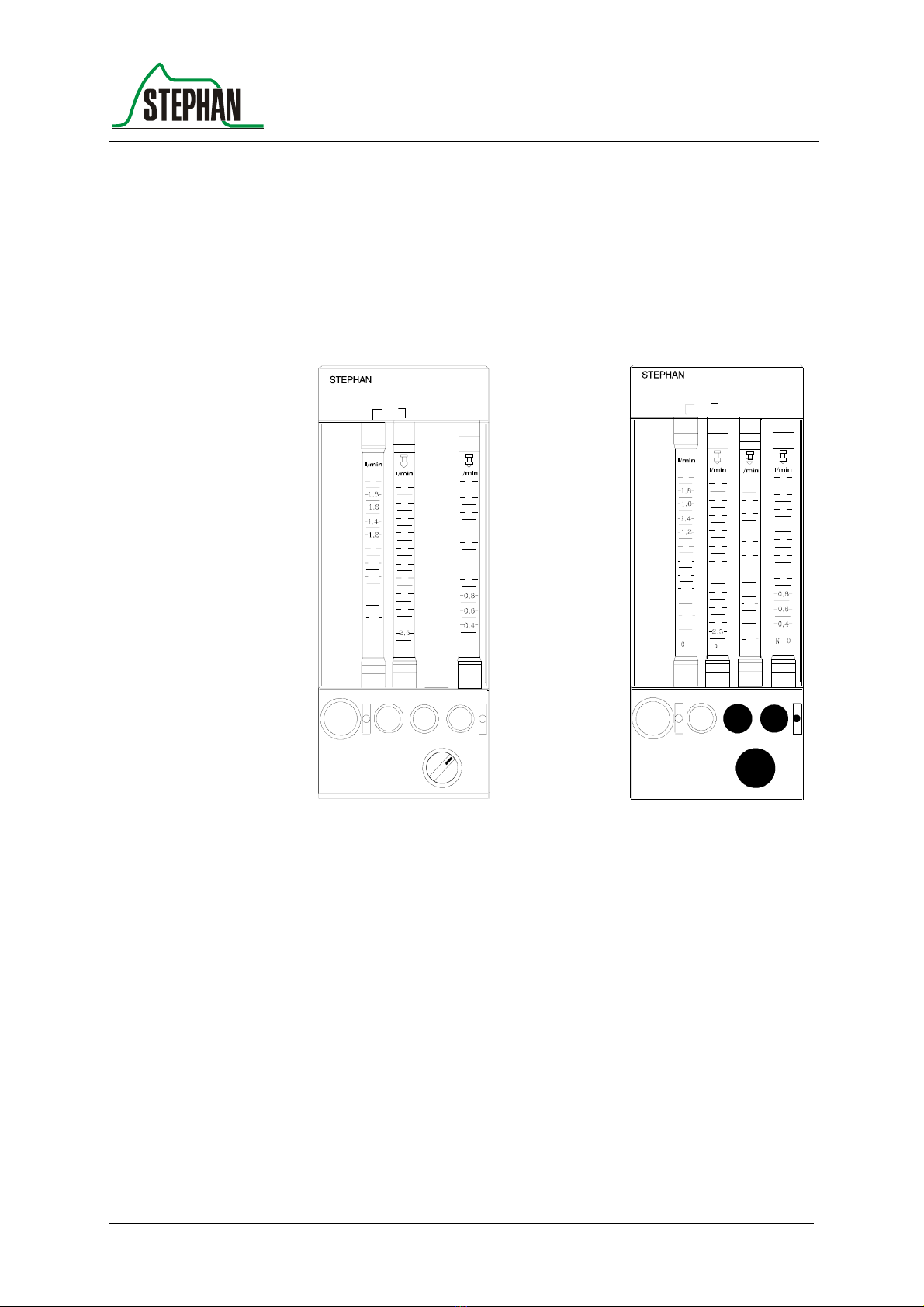
Fig. 1: GME 2 Art.Nr.: 1 150 61 070 GME 3 Art.Nr.: 1 150 61 071
The gas-mixing unit serves as proportioning device for medical gases
(e.g. oxygen, nitrous oxide and compressed air).The desired gases can be
mixed in any relation by means of the proportioning valves below the
flowmeter tubes. The types of gas can be clearly recognized on the
control knobs.
To prevent confusion, the control knob of the regulating valve for oxygen
differs haptically from the two other valves. Inadvertent shift of the
settings is avoided by a special twisting-prevention device.
The proportioning valves (control knobs) permit a continuous flow, when
they are rotated counterclockwise. The measuring area for O2consists of
two flowmeter tubes, so that an exact proportioning is guaranteed.
0
0
0,4
0 FLUSH
2
2
0,2
0,6
1
0,8
2
0,8
N0
2
AIR
2
0,6
0,4
0,2
AIR 2
5
4
3
2
6
2
4
11
6
2
4
6
9
8
7
12
10
88
12
10
12
11
10
AIR N 0
2
2
3Description of Design and Performance
12 SA-103-0109V1.3-HAO-GB ©F. Stephan GmbH
The high precision flowmeter tube (at the left) indicates the measuring
range from 0 to 2 l/min, the "rough" flowmeter tube (at the right)
indicates the flow quantities from 2 to 15 l/min.
Reading line is the upper edge of the float. Graduation of the lower scale
parts of the measuring tubes (AIR/N2O) is more closely stepped.
Because the dimensions of the lateral parts of the GME 2/3 can be altered
optionally, the use of flowmeter tubes of other manufacturers (e.g. Rota,
KDG and others) is possible.
Fig. 2: Gas Mixing Unit
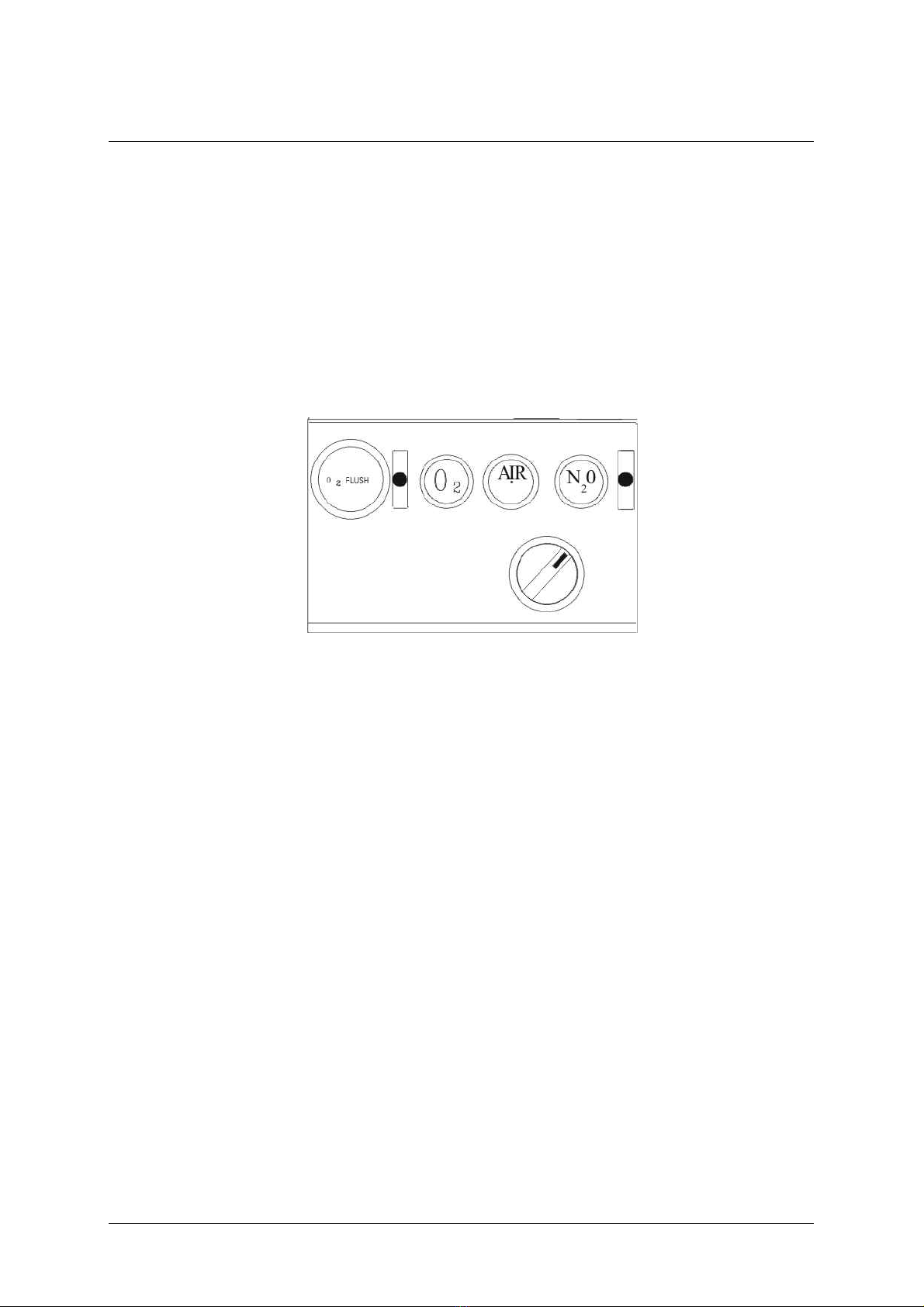
3.1.1 O2-Flush
Depressing the O2-flush-button effects a quick oxygen supply
(approximately 50 l/min) directly to the outlet for fresh gas ( not via the
vaporizer for anaesthetic agent).
Releasing the O2-flush-button effects return to the initial position.
3.1.2 AIR / N2O-Change-Over
The AIR/N2O-change-over-switch is situated below the respective control
knobs (AIR/N2O). It makes preselection of the gases AIR or N2O
possible. The appropriate proportioning of the gases is carried out by
means of the regulating valves O2-Failure Alarm.
In case of a decrease of pressure in the supply system (oxygen
lower than 2,8 bar ) an audible alarm sounds for at least 7 seconds.
No muting is possible.

®
3Description of Design and Performance
©F. Stephan GmbH SA-103-0109V1.3-HAO-GB 13
3.1.3 Nitrous Oxide Blocking
If pressure of oxygen further decreases to approximately 2 bar,the portion
of N2O is also reduced proportionally to the portion of oxygen. In case of
a total failure of oxygen supply, the flow of N2O is reduced to zero.
The readiness for service of the apparatus can only be restored by
providing the prescribed pressure of oxygen of at least 2 bar at the
connection with the supply system.


®
4Vaporizer, Vaporizer holding device
©F. Stephan GmbH SA-103-0109V1.3-HAO-GB 15
4 Vaporizer, Vaporizer holding device
4.1 Vaporizer
Check setting wheel and stop for performance
Check indication of filling level for damage
Check drain screw for easy running and tightness
Check performance of safety filling socket for performance
Check locking device of vaporizer
Verify concentration values of the vaporizer with the help of a testing
device for anaesthetic gases
maximum admissible tolerance in accordance with DIN 13252: +/-
20% of the set value or 0,2 Vol % absolute, always the higher value of
the two.
4.2 Vaporizer holding device
Check sealing valves for tightness
Exchange O-rings
Check for firm fit


®
5Cylinder Supply Unit
©F. Stephan GmbH SA-103-0109V1.3-HAO-GB 17
5 Cylinder Supply Unit
Performance test of the high-pressure gauges for N2O and O2
Check of the connections for supply cylinders
Check of correct coding of threads
Check of the packings of the supply cylinders
Check screw joints and pipe installations for tightness and damages
Check housing for damages
Check attached components for firm fit


®
6Circle System
©F. Stephan GmbH SA-103-0109V1.3-HAO-GB 19
6 Circle System
6.1 Design and Description of Performance
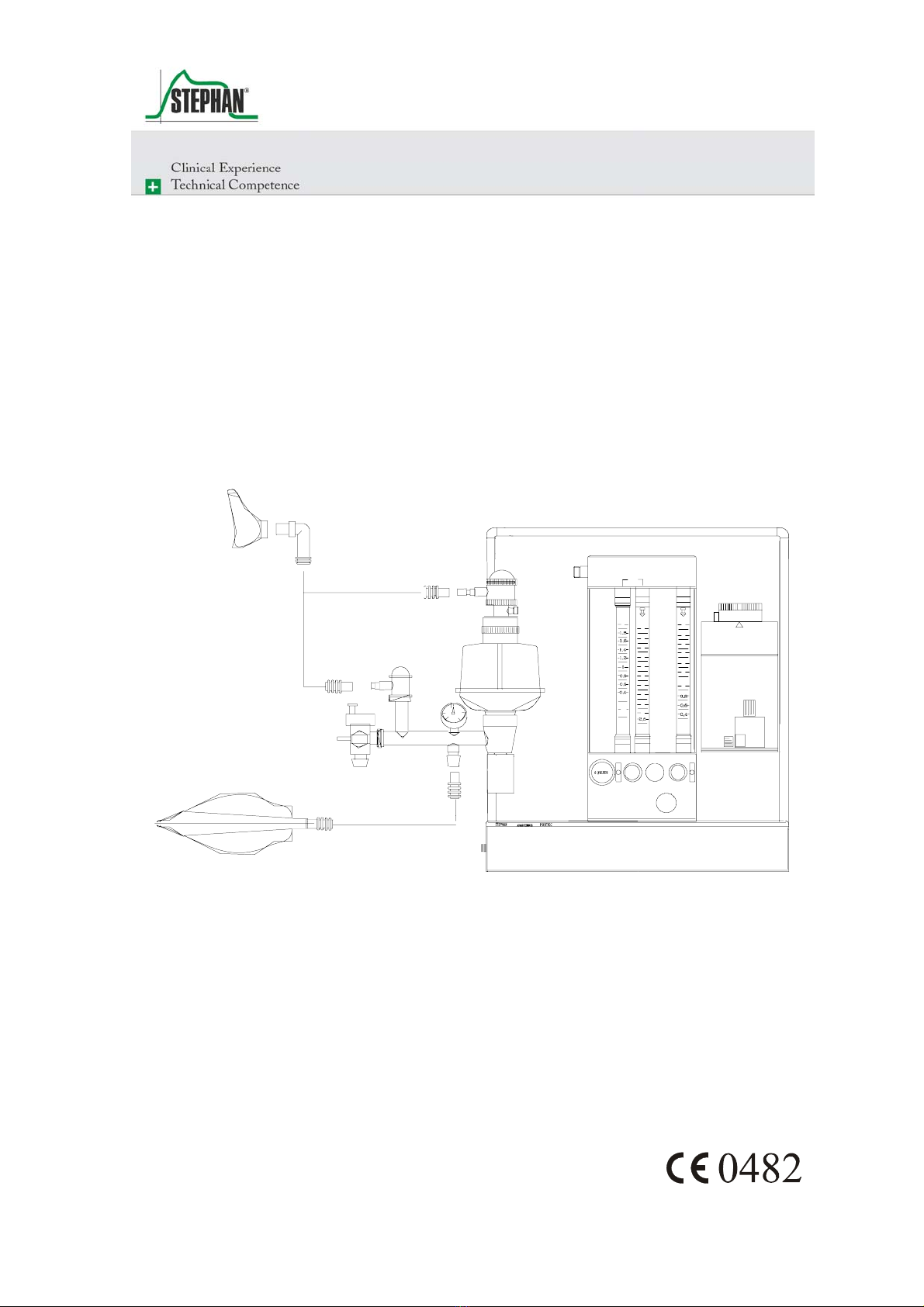
The circle system together with the patient forms a closed cycle, into
which fresh gas is fed via the fresh gas pipe line. Excess gas escapes
through the excess gas valve (10)from the cycle and is removed from the
field of activity of the anaesthetist by means of the suction system for
anaesthetic gas (13).During the inspiration phase, the gas contained in the
system is transported to the patients' lungs by effecting pressure,
produced either by the respirator or by manual operation of a respiratory
bag. The consequent PRESSURE RELIEF in the system during the
expiration phase and the increase of pressure in the lungs due to the
elasticity of the thorax makes the gas flow back out of the lungs. Thereby
it is the task of the inspiration valve (1) and the expiration valve (7) to
permit the flow of gas only in one direction and so to establish the cycle.
Prior to reaching the patient again, CO2is removed in the two absorbers
(2). Humidity and heat given off by the patient are fed back to him in
such a semi-closed system, which prevents desiccation and excessive
cooling of the airways. The fresh gas feeder is located on the lower end of
the holding tube. The adjustability of elevation and the possible
swivelling stand for a good adaptation to the local conditions of the
operating theatre. The respiratory pressure gauge(3), which can be
slipped onto the holding device of the circle system, has a measuring
range from - 10 to 100 mbar. It can be replaced by a blind plug.
As a standard, a mechanic volumeter (9) is installed below the expiration
valve, which measures all expiratory values of respiratory volume. The
measuring of O2-concentration, required
in accordance with DGAI, is carried out by means of a polarographic cell
(by Clark) (1) at the head of the inspiration valve. Moreover, the circle
system is provided with connection tapers in accordance with ISO
respectively DIN 13 252, so that corrugated tubes for the ventilation of
adults as well as tube systems for infants can be used. The excess valve
(10) serves to carry off spent respiratory gases. It can be operated in four
different adjustments.

6Circle System
20 SA-103-0109V1.3-HAO-GB ©F. Stephan GmbH
6.1.1 CL (closed)
The valve is completely closed. This setting is necessary for operation in
respirator mode. In this mode, the spent respiratory gases are evacuated
via the ejector on the patient component during the expiration phase.
6.1.2 Pressure Range from 5mbar to 50mbar
This setting is used to limit the maximum pressure during manual
ventilation. When the set pressure is reached, the valve evacuates.
6.1.3 Spontaneous Respiration
During spontaneous respiration of the patient under light anaesthesia, the
valve closes in the inspiration phase, the patient now breathes the fresh
gas provided by the apparatus. In the expiration phase, the valve opens
and evacuates the system until ambient pressure is reached.
This setting is to be used in case of assisted ventilation with the patient
triggering the respiration and the respirator deepening the respiration.
Aside of that, it is possible to switch to SP briefly in case of manual
ventilation in the pressure range of 5 to 50 mbar to evacuate an overfilled
respiratory bag.
6.1.4 VOL (volume-controlled ventilation)
With the valve setting VOL, the circle system is closed automatically to
guarantee supply of the patient with the desired respiratory working
volume. Spent and excess respiratory gases escape from the valve at the
end of the expiration phase. During the expiration phase, pressure in the
system never rises above 1,5 mbar.
This manual suits for next models
1
Table of contents
Other Stephan Medical Equipment manuals


