QA4 Surgery Trolley System – Powered Function, Version 2 Operating Instructions
Document No. 992010 Issue 8, 05.03.13 Page 6
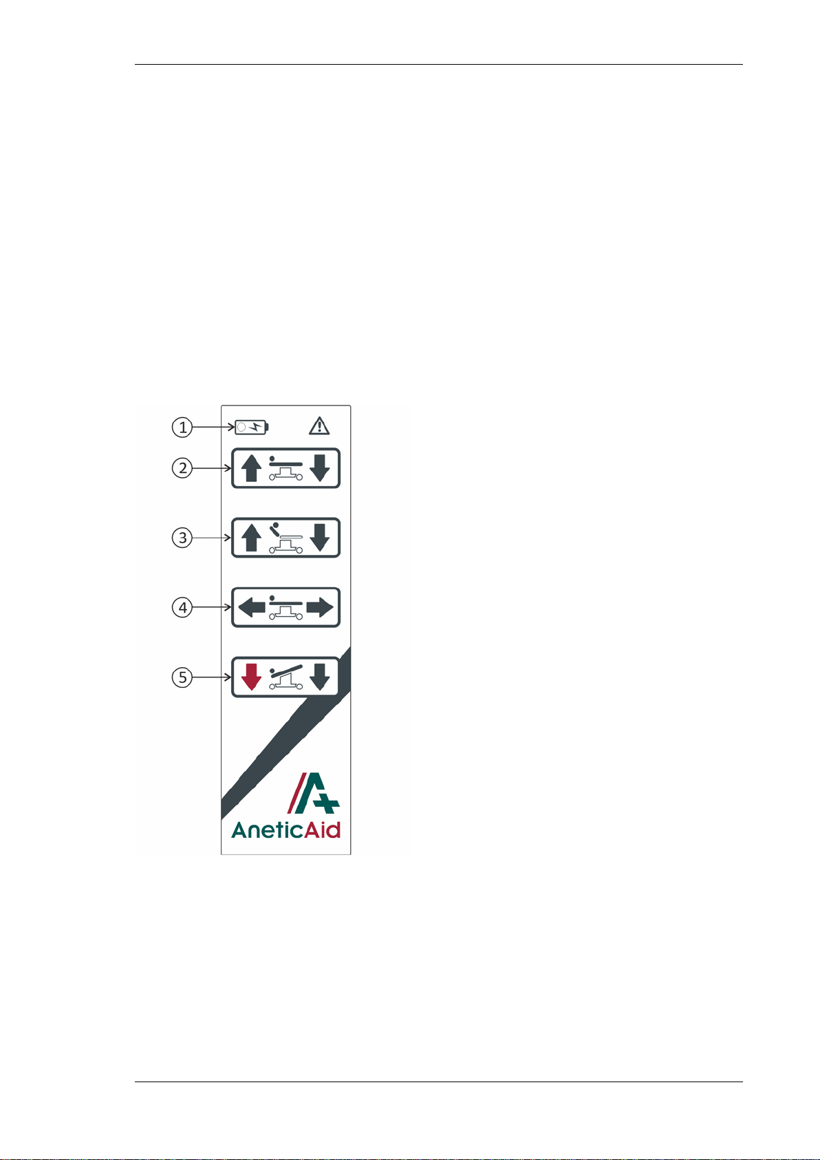
3.1.5. Using the Trendelenberg
Function
The patient platform can be
longitudinally tilted to provide a
trendelenberg (head down) or reverse
trendelenberg (leg down) position by
using one of the two down buttons on
the handset.
The head down trendelenberg button is
in-filled in red to indicate that this button
is used for emergency positioning.
CAUTION: Ensure that there are no
obstructions in the way before tilting the
patient platform.
CAUTION: Ensure that there is no
equipment stored in the base moulding
of the trolley before tilting the patient
platform (NOTE: This ONLY applies when
the trolley is at its lowest height).
3.2. Manual Trolley Functions
The following functions are manually
operated and are not powered from the
on-board battery supply or mains.
3.2.1. Using the Brakes
All four castors are braked simultaneously
by depressing either of the brake pedals
(no.2, fig.2) at any point along the length
of the pedal. The brakes are disengaged
by lifting either pedal.
3.2.2. Using the Steering Pedal
The trolley can be manoeuvred more
easily by engaging the steering
mechanism. The mechanism is engaged
by pressing the steering pedal (no.3,
fig.2) and disengaged by lifting the
pedal.
CAUTION: Applying the steering pedal
with excessive force, i.e. by standing on
the pedal, will cause permanent
damage to the mechanism.
CAUTION: The steering pedal is designed
to disengage automatically when the
trolley is pushed leg first over an
obstruction. Attempting to prevent this
will cause damage to the mechanism.
The 5th wheel should be allowed to
disengage and then can be reengaged
after the obstruction.
CAUTION: The steering wheel must be
disengaged manually when the trolley is
pushed head first over an obstruction, i.e.
a lift threshold, or damage may occur.
3.2.3. Using Lateral Tilt
Lateral tilt is achieved by rotating the
lateral tilt handle (no.4, fig.2) either
clockwise or anti-clockwise.
To use the lateral tilt handle; extend the
handle by pulling it away from the trolley,
and unfold the crank handle until it locks
into position. Return the handle to its
stored position when not in use.
CAUTION: The lateral tilt handle must be
stored away to ensure that the handle
does not get damaged.
Fig. 5
3.2.4. Using the Head Section
The head section is articulated by simply
pulling up on the head section tilt
actuation lever.
The head section is also designed to be
removed for specific theatre procedures;
i.e. gynae and urology, to give greater
anaesthetist access to the patient.
Removing the head section prior to
administering anaesthetic reduces the
length of the backrest and the need to
reposition the patient in theatre.
Removing the head section also gives