52 06/2011 Rev. 7.4
Model 2009
06/2011 Rev. 7.4 53
Model 2009
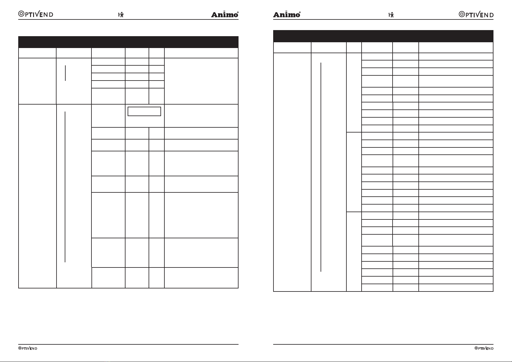
2.3 The service menu
Service menu
Main item Sub item Item Range Set Description
2.1 Quick recipe
* From software
V4.0
Recipe name 1
Recipe name 10
Cup volume
50-250 ml 120ml * 2.1 Quick recipe change into Quick
recipe Pro. Set here directly your
ingredient dispensing time (sec.)
Use this for setting the volume and
strength of coffee, milk, sugar and cocoa
easily per recipe (drink key).
Only the ingredients applicable to the
recipe are shown.
Ingredient 1
0,0 - 50,0 s
Ingredient 2
0,0 - 50,0 s
Ingredient 3
0,0 - 50,0 s
Ingredient 4
0,0 - 50,0 s
2.2 Button setting Button 1
Button 10
<Recipe> +
,
Recipe list see
section 3.3
Change any recipe buttons here that
standard factory settings. All settings
that correspond to selected recipes are
automatically loaded.
Recipe active Yes/no Yes Use this to place the product concerned
out of service.
Price 0,05-
100,00
0,10 For paid dispensing a price can be set
here for each product button.
Cup volume 50-250ml * 120ml Set the desired cup volume here. All other
parameters (e.g. coffee dosage) can be
adjusted automatically. This parameter is
linked to the cup volume item in the menu
2.1 Quick recipe!
Multicup 0-20 0 Set the number of cups that should be
dispensed when the key switch is in the
jug setting.
Key switch 0-1-2-3 0 / 1 Recipe button concerned works as follows:
0= key switch setting n/a
CUP (paid) or JUG* (paid)
1= key switch |: CUP (paid)
key switch –: JUG* (paid)
2= key switch |: no dispensing
key switch –: JUG* (paid)
3= key switch |: CUP (paid)
key switch –: JUG* (free)
(*when multicup is set to >1)
Push & Hold Yes-No No If set to yes: pressing this button starts the
hot/cold water dispensing and releasing it
stops the hot water dispensing.
Use this option only for DV4 , DV5 and
DV 6 in combination with a hot/cold water
recipe button.
Drip time 0-10 sec. 2 sec. The length of time that the product
continues to run from the brewer or mixer.
After this time has elapsed a new drink
selection can be made.
Service menu continued ….
Main item Sub item Sub Item Range Description
2.3 Recipe setting <Recipe name> 1
<Recipe name> 10
Unit 1 DV 1 WT 0,0-90,0 s Waiting time Water 1
DV 1 0-100 ml Dispensing amount Water 1
Rinse 1 WT 0,0-20,0 s Waiting time Rinsing Water 1
Rinse 1 0-15 ml Dispensing amount Rinsing Water 1 Auto-
matically deducted from Water 1
Ingredient 1 WT 0,0-90,0 s Waiting time Ingredient 1
Ingredient 1 0,0-50,0 s Product dispensing time Ingredient 1
Ingredient 2 WT 0,0-30,0 s Waiting time Ingredient 2
Ingredient 2 0,0-50,0 s Product dispensing time Ingredient 2
Mixer1 WT 0,0-90,0 s Waiting time Mixer 2
Mixer 1 0,0-50,0 s Mixing time Mixer 2
Unit 2 DV 2 WT 0,0-30,0 s Waiting time Water 2
DV 2 0-100 ml Dispensing amount Water 2
Rinse 2 WT 0,0-20,0 s Waiting time Rinsing Water 2
Rinse 2 0-15 ml Dispensing amount Rinsing Water 2 Auto-
matically deducted from Water 2
Ingredient 3 WT 0,0-30,0 s Waiting time Ingredient 3
Ingredient 3 0,0-50,0 s Product dispensing time Ingredient 3
Ingredient 4 WT 0,0-30,0 s Waiting time Ingredient 4
Ingredient 4 0,0-50,0 s Product dispensing time Ingredient 4
Mixer 2 WT 0,0-30,0 s Waiting time Mixer 2
Mixer 2 0,0-50,0 s Mixing time Mixer 2
Unit 3
*
DV 3 WT 0,0-30,0 s Waiting time Water 3
DV 3 0-100 ml Dispensing amount Water 3
Rinse 3 WT 0,0-20,0 s Waiting time Rinsing Water 3
Rinse 3 0-15 ml Dispensing time Rinsing Water 3
Automatically deducted from Water 3
Ingredient 5 WT 0,0-30,0 s Waiting time Ingredient 5
Ingredient 5 0,0-50,0 s Product dispensing time Ingredient 5
Ingredient 6 WT 0,0-30,0 s Waiting time Ingredient 6
Ingredient 6 0,0-50,0 s Product dispensing time Ingredient 6
Mixer 3 WT 0,0-30,0 s Waiting time Mixer 3
Mixer 3 0,0-50,0 s Mixing time Mixer 3
* Unit 3 is not used