The following routine maintenance items are only for reference, please refer
to relevant standards and operation instructions for operation;
Sunshade and rainproof measures shall be taken for the charging pile, and
it is recommended to install a canopy outdoors;
Regularly check whether the bolts of the charging pile are fastened, whether
the connecting wire is loose, and whether the connection is not firm, and
check whether there is short circuit;
Pay attention to lightning protection and ensure eective shielding and
reliable grounding of the charging pile;
When using, try to control the output voltage and current of the charging pile
within the nominal range, so as to ensure that the charging pile can work with
the maximum eciency;
When the charging pile is out of service, the charging output shall be stopped
first, then the power plug shall be pulled out and the power shall be cut o, then
the cable shall be wound, and the charging pile shall be put back to its
original position after the temperature of the charging pile drops to normal
temperature;
●
●
●
●
●
●
Notice
The charger must be grounded through the grounding conductor of the
permanent wiring system or equipment;
Please avoid installing in the direct sunlight or exposure environment, and try to
use the charger in a cool and ventilated place;
Do not install and use the charger near flammable, explosive, combustible
and chemical substances or steam;
Before installing or cleaning the charger, the power supply must be cut o to
ensure that there is no power input. Do not touch the heat source, dirt or water
source on the contact surface;
Please use the charger within the specified working parameters;
Only connect electric vehicles. Do not connect other loads (electric tools, etc.).
Do not use the charger for other purposes than charging or other vehicles that
do not support the AC charger standard of the country where the product is
located;
The charger must be checked regularly. If it is found to be defective, cracked,
worn, damaged and inoperable, the charger shall be stopped immediately and
the after sales service telephone shall be called;
Do not attempt to open, disassemble, modify or transform the charger without
a professional electrician. The charger is not a device that can be maintained
by users. Do not remove safety symbols, warning prompts, nameplates, signs
or pipeline marks;
If you or your car are exposed to rainstorm, lightning, heavy snow or other
severe weather conditions, do not use the charger to prevent any parts from
being damaged;
Please handle with care when transporting the charger. Do not subject it to
strong external force impact, and do not drag, twist or step on the charger and
cable to prevent damage to any parts. At any time, please avoid and prevent
the charger from being damaged by moisture, liquid and other foreign matters.
If there is water, damage or corrosion, please do not use it. Do not touch or
charge the cable and charging gun head with wires, tools or other sharp
hard objects;
If your EV is covered with a car cover or a car coat, please remove it before
charging the car;
Users may aect or impair the function of the charger during usage if he/she
wears any medical or implantable electronic device, such as cardiac
defibrillators, pacemakers, etc;
USER MANUAL 13
7. MAINTENANCE
7. MAINTENANCE
USER MANUAL 14
7.1 Maintenance
7.2 Important Matters
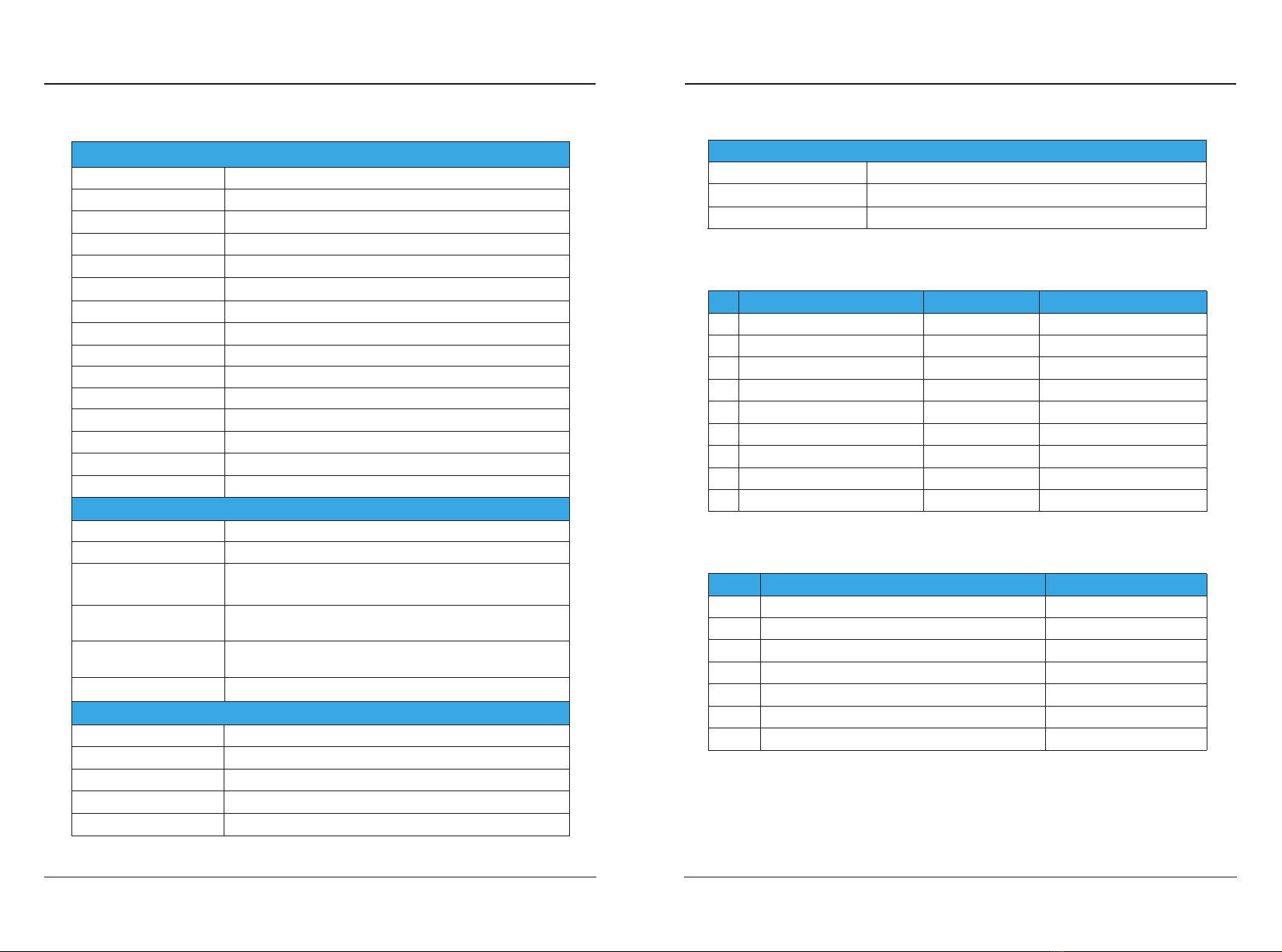
L1 KA1
AC220V
DC12V
KA2
KA1 KA2
L N
L2
PE
relay control relay control
MAIN CONTROL CIRCUIT
POWER MODULE
temperature control
LED
electricle
leakage detection
L1
L2
PE
CP
EV connector
overvoltage & under
voltage protection
12V+output
12V-
12V+output
12V-
power supply
The output side connects the EV connector
The input side is connected to the mains
To ensure that you can enjoy the warranty service, please ensure that the tear-
proof label on your charging pile is intact;
Your charging pile warranty is based on the date of purchase by the user and, if not
available, the date the unit left the factory;
Please show the original of the unit and invoice during warranty.
●
●
●
1)
2)
3)
4)
5)
6)
7)
8)
9)
10)
11)
12)
13)
14)