Ankom TDF Series Manual

Paddle Bar Replacement
TDF
Service Procedure TS021
Revised: 01/24/2017
ANKOM Technology 2052 O’Neil Road Email: service@ankom.comPhone: 315-986-8090 Fax: 315-986-8091
pg. 1 of 9
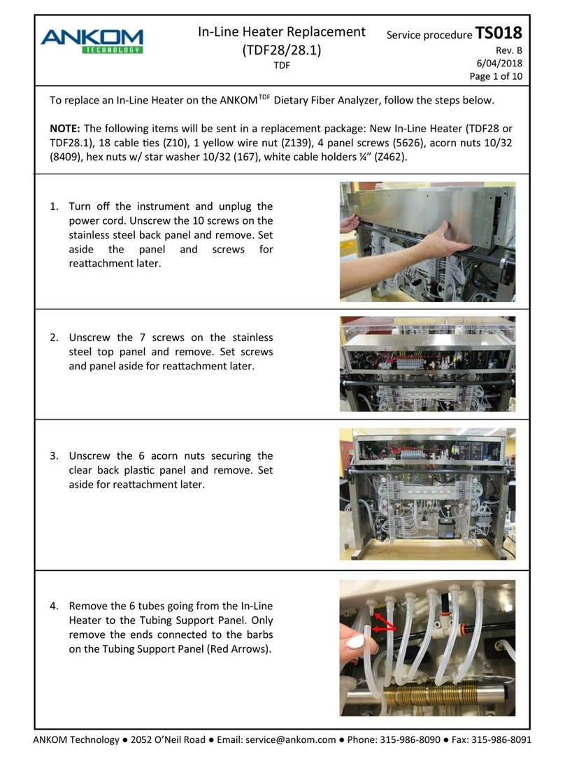
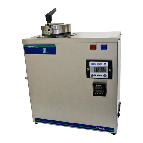
This procedure is to help facilitate the replacement of the TDF23 Paddle Bar Assembly on the ANKOMTDF Dietary Fiber
Analyzer.
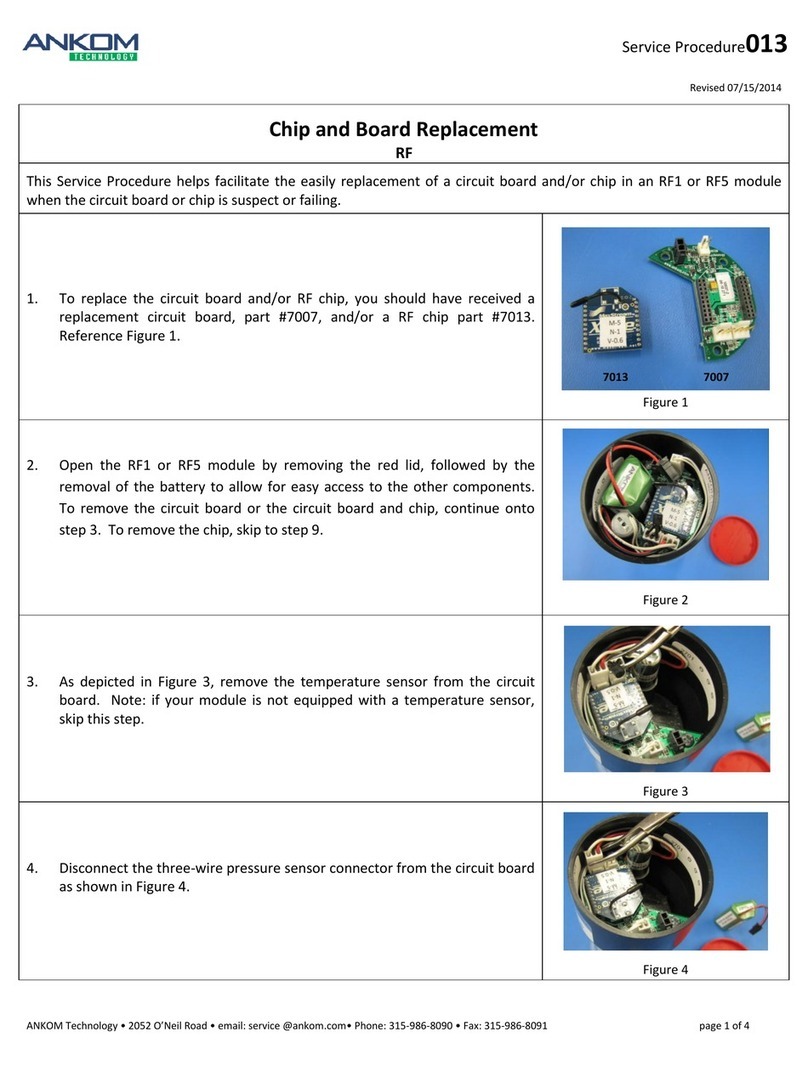
Note: The following items will be sent in a replacement package as part of the TDF23 Paddle Bar Replacement Kit.
New Paddle Bar Assembly
4 Shims (0.015)
5/32” Hex key wrench
Loctite
2 Screws #8269
3/32” Hex key wrench
1 Shoulder Screw
Depth gauge
1/8” Hex key wrench
1.
Prepare the instrument for service.
a. Power off the instrument.
b. Remove the clear back panel of the TDF instrument by
removing the six acorn nuts using a 3/8” nut driver
(provided with the original instrument purchase).
2.
Tilt the instrument forward (if necessary) for easy access
to the back of the TDF.
a. Unscrew the two black Service Access screws on the
upper right and left sides of the instrument (near the
ends of Clamp Bar A).
b. Remove the four front clamp bars and set them aside.
c. Clear the area in front and immediately behind the
instrument of any items that might be in the way.
d. Tilt the instrument forward, careful to guide it down
slowly to ensure no tubing gets caught or pinched in the
machine.
6 Acorn Nuts
Remove
Clamps
Service
Access
Screws
Tilt
Forward

Paddle Bar Replacement
TDF
Service Procedure TS021
Revised: 01/24/2017
ANKOM Technology 2052 O’Neil Road Email: service@ankom.comPhone: 315-986-8090 Fax: 315-986-8091
pg. 2 of 9
3.
Unplug the black 25 pin Cable Connector plug.
Twist counter-clockwise from the underside of the Electrical
Enclosure (right side from the front) and pull to release the
plug.
4.
Unscrew the Shoulder Screw that connects the cable block
to the mixer piston.
Using the 1/8” Hex key wrench, unscrew the Shoulder
Screw on the Paddle Bar Assembly sticking through the hole
in the front of the instrument, connecting to the brass Rod
End of the Mixer Piston. Set the Shoulder Screw aside for
later use.
5.
Unscrew the 4 screws holding the Paddle Bar Assembly
onto the front of the instrument.
a. Lift the instrument to its upright position.
b. Use the 5/32” Hex key wrench to remove the screws.
Be careful while doing this as the Paddle Bar Assembly
will fall out when the last screw is removed.
Twist
& Pull
Shoulder
Screw
Hold
Left side
Paddle Bar
Hinge Post
5/32”
Hex Key
Wrench

Paddle Bar Replacement
TDF
Service Procedure TS021
Revised: 01/24/2017
ANKOM Technology 2052 O’Neil Road Email: service@ankom.comPhone: 315-986-8090 Fax: 315-986-8091
pg. 3 of 9
6.
Gently feed the black 25 pin Cable Connector plug through
the hole in the front of the instrument, being careful not
to get it caught on the tubing and air lines.
7.
Set the faulty Paddle Bar Assembly aside for return to ANKOM.
8.
Prepare the new replacement Paddle Bar Assembly.
Remove the cable-tie from the Paddle Bar Hinge Post on the
left side. Be careful as the hinge block will fall off the Hinge
Pin if tilted.
9.
Install the new Paddle Bar Assembly.
Feed the black 25 pin Cable Connector through the hole in
the front of the instrument.
10.
Loosely install the four screws.
Line up the two Paddle Bar Hinge Posts with the four screw
holes to the right and left being sure to loosely install the
four screws with the 5/32” Hex key wrench.
Cable-tie
on
Left side
Hinge Post
Front view
Cable
Connector
Hole
Rear view
Cable
Connector
inserted
through hole
5/32”
Hex Key
Wrench
Cable
Connector

Paddle Bar Replacement
TDF
Service Procedure TS021
Revised: 01/24/2017
ANKOM Technology 2052 O’Neil Road Email: service@ankom.comPhone: 315-986-8090 Fax: 315-986-8091
pg. 4 of 9
11.
Place the four shims in their appropriate positions.
a. Set the four 0.015” Shim spacers (provided in the new
Paddle Bar kit) underneath the #1, 2, 5 & 6 paddles and
set on top of Clamp Bar B to properly distance the
Paddle Bar Assembly from Clamp Bar B. When doing
this, allow the paddles to rest on the shims while tilting
the paddles back so that the bottom front corner of each
paddle is the only part of the paddle that is touching the
shims. In this position the face of the paddles will not
be perfectly vertical but slightly tilted back at the
bottom.
b. With the paddles held in a tilted back position, tighten
the four screws in the Paddle Bar Hinge Posts using the
5/32” Hex key wrench.
c. Once the screws are tight, remove the four Shim spacers
from beneath the paddles.
12.
Plug the 25 pin Cable Connector into its socket in the
underside of the Electrical Enclosure.
a. Carefully tilt the instrument forward.
b. Make sure the cable is not caught up in the tubing or air
lines in the back of the instrument.
c. When plugging the connector in, align the pins to the
sockets within the connector and twist clock-wise until
it stops turning.
d. Check to make sure it cannot be pulled out (it should
lock in place).
13.
Finger-tighten the Shoulder Screw.
This will connect the cable block (on the Paddle Bar
Assembly sticking through the hole in the front of the
instrument) to the brass Rod End of the Mixer Piston in
order to secure the Paddle Bar while testing it in the
following steps.
Align
Cable
Connector
Sockets
Shoulder
Screw
Shim
Spacers
underneath
Paddle

Paddle Bar Replacement
TDF
Service Procedure TS021
Revised: 01/24/2017
ANKOM Technology 2052 O’Neil Road Email: service@ankom.comPhone: 315-986-8090 Fax: 315-986-8091
pg. 5 of 9
14.
Check the back stroke of the paddles.
a. Return the instrument to the upright position.
b. Using the depth gauge (provided in the new Paddle Bar
kit) with the Paddle Bar Assembly in the back stroke
position (this is its normal, at rest, position) rest the
squared-off end of the depth gauge against the bottom
edge of the #5 paddle.
c. Measure the distance from the bottom edge of this
paddle to the face of the orange gasket on Clamp Bar B.
This distance should be 10/32”. If this distance is not
correct contact ANKOM Technology for instructions on
how to make an adjustment.
Depth
Gauge
10/32”
Distance
10/32”
Distance
4/32” –5/32”
Distance

Paddle Bar Replacement
TDF
Service Procedure TS021
Revised: 01/24/2017
ANKOM Technology 2052 O’Neil Road Email: service@ankom.comPhone: 315-986-8090 Fax: 315-986-8091
pg. 6 of 9
15.
Check the forward stoke of the paddles.
a. Rest the squared-off end of the depth gauge against the
face of the orange gasket on Clamp Bar B just in front
of paddle #5.
b. Using either paddle #1 or #6 in your opposite hand,
rotate the paddles forward so that they extend to their
forward position.
c. Looking straight down on paddle #5, measure the
distance that the bottom edge of this paddle extends
beyond the orange gasket. This distance should be
4/32” - 5/32”. If this distance is not correct contact
ANKOM Technology for instructions on how to make
an adjustment.
Rotate
Paddles
Forward
4/32” - 5/32”
Distance
10/32”
Distance
4/32” –5/32”
Distance
Depth
Gauge

Paddle Bar Replacement
TDF
Service Procedure TS021
Revised: 01/24/2017
ANKOM Technology 2052 O’Neil Road Email: service@ankom.comPhone: 315-986-8090 Fax: 315-986-8091
pg. 7 of 9
16.
Secure the Shoulder Screw in place.
a. Tilt the instrument forward to access the back once
again.
b. Remove the Shoulder Screw installed finger-tight in the
previous step.
c. Apply a drop of Loctite 242 (provided in the new
Paddle Bar kit) to the threads of this screw.
d. Re-install the screw (do Not to get the Loctite on the
brass Rod End of the Mixer Piston) and tighten with the
⅛” Hex key wrench.
e. Return the instrument to its upright position.
f. Reinstall the two Service Access screws.
Depth
Gauge
Apply
Loctite
1/8”
Hex key
Wrench
Service
Access
Screws

Paddle Bar Replacement
TDF
Service Procedure TS021
Revised: 01/24/2017
ANKOM Technology 2052 O’Neil Road Email: service@ankom.comPhone: 315-986-8090 Fax: 315-986-8091
pg. 8 of 9
17.
Adjust the reported temperatures on the Touch Screen
Display with a calibrated thermometer accurate to at least
0.2˚C.
a. Obtain a calibrated thermometer and place it in the
immediate environment of the paddles.
b. Allow the temperature reading to equilibrate with the
environment.
c. Turn the TDF instrument on.
c-1. From the Select a Function screen, press Diagnostics
c-2. Service Mode
c-3. Temperature Sensor Corrections
c-4. Enter temperature offsets into the fields for each
station. For example, if the calibrated thermometer is
showing a temperature of 23.2˚C but the Uncorrected
temperature value for station 1 is showing a
temperature of 24.0˚C, enter an offset of -0.8˚C. If the
Uncorrected temperature value for station 2 is
showing a temperature of 23.0˚C, enter an offset of
0.2˚C. Whatever number is entered as the offset
(whether positive or negative) will be added to the
uncorrected value.
c-5. Write down the offset numbers you put in for each
Paddle Bar to later ensure they save to the instrument.
c-6. Select Save to Permanent Memory and exit out of
Diagnostics.
d. Turn the instrument off and then on again to check to
ensure the corrected value information saved properly.
e. Follow the above screen display selections again and check
to ensure the Temperature Sensor Corrections match those
that you wrote down after adjusting.
Thermometer

Paddle Bar Replacement
TDF
Service Procedure TS021
Revised: 01/24/2017
ANKOM Technology 2052 O’Neil Road Email: service@ankom.comPhone: 315-986-8090 Fax: 315-986-8091
pg. 9 of 9
18.
Reinstall the back panel.
Replace the clear back panel of the TDF instrument securing it with the six acorn nuts removed in the first step.
With this completed you are now ready to return your TDF instrument to service. Contact ANKOM Technology for
instructions on returning the faulty Paddle Bar Assembly.
Other manuals for TDF Series
2
This manual suits for next models
1
Other Ankom Measuring Instrument manuals