manuals.online logo
Brands
  1. Home
  2. •
  3. Brands
  4. •
  5. ANTAIRA
  6. •
  7. Network Router
  8. •
  9. ANTAIRA LNP-2004G-SFP Series User manual

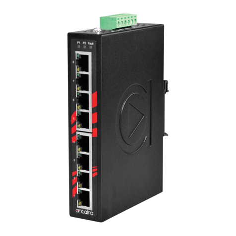
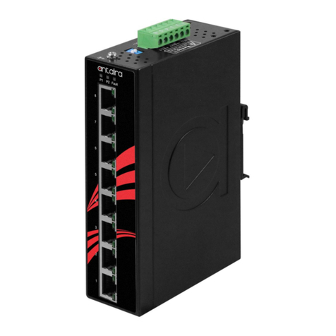
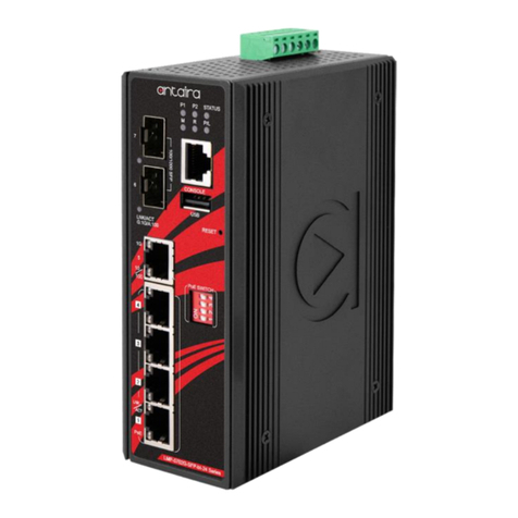
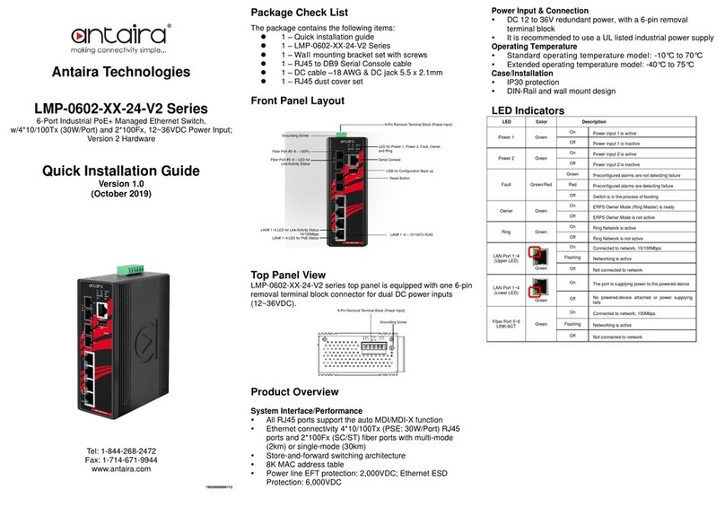
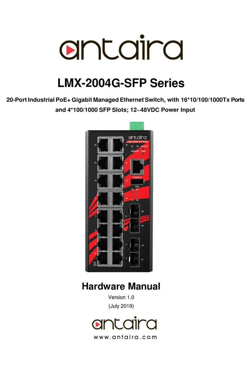
ANTAIRA LNP-2004G-SFP Series User manual

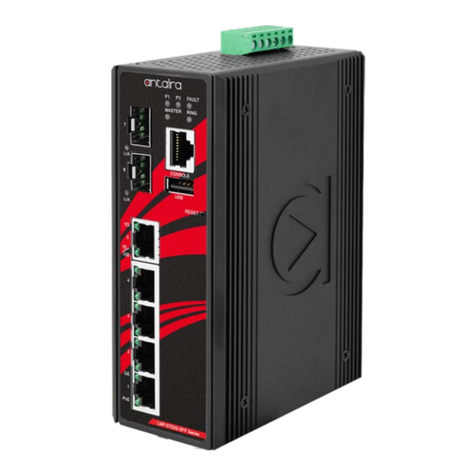
Antaira Technologies
LNP-2004G-SFP Series
20-
Port Industrial PoE+ Unmanaged Gigabit EthernetSwitch,
w/16*10/100/1000Tx (30W/Port) + 4*100/1000 SFPSlots
Package Check List
The package contains the following items:
1 –Quick installation guide
1 –LNP-2004G-SFP(-T)
1 –Wall mounting bracket set with screws
1 –DC cable –18 AWG & DC jack 5.5 x2.1mm
1 –RJ45 dust cover set
Front Panel Layout
6-Pin Removal Terminal Block (Power Input)
Grounding Screw
LED for Power 1, Power 2 andFault
LAN# 1~16 –LED for PoEStatus
Power Input & Connection
DC 48 to 55V redundant power, with a 6-pin removal
terminal block
It is recommended to use a UL listed industrial powersupply
Operating Temperature
Standard operating temperature model: -10°C to 65°C
Extended operating temperature model: -40°C to 75°C
Case/Installation
IP30 protection
DIN-Rail and wall mount design
LED Indicators
Quick Installation Guide
Version 1.1
(July 2020)
LAN# 1~16 –LEDfor Link/Activity Status
1000Mbps
LAN# 1~16 –LED for Link/Activity Status
10/100Mbps
LAN# 1~16 –10/100/1000Tx RJ45
SFP# 17~20 –LED for Link/Activity Status
SFP# 17~20 –100/1000 SFP Slots
Top Panel View
LNP-2004G-SFP series’ top panel is equipped with one 6-pin
removal terminal block connector for dual DC power inputs
(48~55VDC).
Tel: 1-844-268-2472
Fax: 1-714-671-9944
www.antaira.com
19020000000075
6-Pin Removal Terminal Block (Power Input)
Product Overview
System Interface/Performance
All RJ45 ports support the auto MDI function
Embedded 16*10/100/1000Tx (PSE: 30W/Port) and
4*100/1000 SFP slots
Store-and-Forward switching architecture
8K MAC Address Table
Supports 9,216bytes Jumbo Frame
512Kbytes memory buffer
LED
Color
Description
Power 1
Green
On
Power input 1 is active
Off
Power input 1 is inactive
Power 2
Green
On
Power input 2 is active
Off
Power input 2 is inactive
Fault
Red
On
Power input 1 or 2 is inactive
Off
Both power input 1 and 2 are active
PoE Indicator
(Port 1~16)
Green
On
The port is supplying power to the powered-device
Off
No powered-device attached or power supplying fails
LAN Port
(Port 1~16)
Green
On
Connected to network, 1000Mbps
Flashing
Networking is active
Off
Not connected to network
Green
On
Connected to network, 10/100Mbps
Flashing
Networking is active
Off
Not connected to network
SFP Port
LINK/ACT
(Port 17~20)
Green
On
Connected to network, 1000Mbps
Flashing
Networking is active
Off
Not connected to network
Amber
On
Connected to network, 100Mbps
Flashing
Networking is active
Off
Not connected to network
Grounding Screw
Quick Installation
Ethernet Ports
RJ45 Ports (Auto MDI)
All RJ45 ports are auto-sensing for 10Base-T, 100Base-TX, or
1000Base-T device connections. Please follow the wiring pin
assignment table for Ethernet port installation.
RJ45 Ethernet Port Pin Outs
Pins
T568A Color
T568B Color
10Base-T,
100Base-TX
1000
Base-T(X)
Pin 1
white/green stripe
white/orange stripe
Rx+
TP0+
Pin 2
green solid
orange solid
Rx-
TP0-
Pin 3
white/orange stripe
white/green stripe
Tx+
TP1+
Pin 4
blue solid
blue solid
unused
TP2+
Pin 5
white/blue stripe
white/blue stripe
unused
TP2-
Pin 6
orange solid
green solid
Tx-
TP1-
Pin 7
white/brown stripe
white/brown stripe
unused
TP3+
Pin 8
brown solid
brown solid
unused
TP3-
Power Input Wiring
Please follow the steps below to insert the power wire:
1. Insert the positive and negative wires into the PWR1
(V1+, V1-) and PWR2 (V2+, V2-) contacts on the
terminal block connector as shown below in Figure 1.
2. Tighten the wire-clamp screws to prevent the wires
from loosening, as shown below in Figure 2.
Figure 1 Figure 2
Industrial Switch Mounting
DIN-Rail Mounting
The DIN-Rail bracket is pre-installed on the industrial Ethernet
switch from the factory. Please refer to Figure 3 for a DIN-Rail
bracket installation reference.
Follow the steps below for installing
the industrial switch on the DIN-
Rail track:
1. Insert the top of the DIN-Rail
on to the track as shown in
Figure 4.
2. Lightly pull down the bracket
on to the rail as shown in
Figure 5.
3. Check if the bracket is
mounted tightly on the rail.
4. To remove the industrial
Ethernet
switch
from the rail, do the opposite from the steps above.
Figure 4
Wall Mounting
Follow the steps below to mount the industrial Ethernet switch
using the wall mounting bracket as shown below in Figure 6.
1. Remove the DIN-Rail bracket from the industrial Ethernet
switch by loosening the screws.
2. Place the wall mounting
brackets on the top and
bottom of the industrial
Ethernet switch.
3. Use the screws to screw the
wall mounting bracket onto the
industrial Ethernet switch.
4. Use the hook holes at the
corners of the wall mounting
bracket to hang the industrial
Ethernet switch on the wall.
5. To remove the wall mount
bracket, do the opposite from
the steps above.
Field Maintenance and Service
If the device requires servicing of any kind, the user is
required to disconnect and remove it from its mounting. The
initial installation should be done in a way that makes this
as convenient as possible.
Voltage/power lines should be properly insulated as well as
other cables. Be careful when handling them so as to not
trip over.
Do not under any circumstance insert foreign objects of any
kind into the heat dissipation holes located in the different
faces of the device. This may not only harm the internal
layout, but might cause harm to user as well.
Do not under any circumstance open the device for any
reason. Please contact your dealer for any repair needed or
follow the instructions within the manual.
Warranty Policy
Warranty Conditions
Products supplied by Antaira Technologies are covered in this
warranty for sub-standard performance or defective
workmanship. The warranty is not, however, extended to
goods damaged in the following circumstances:
(a) Excessive forces or impacts
(b) War or an Act of God: wind storm, fire, flood, electric
shock, earthquake
(c) Use of unqualified power supply, connectors, or
unauthorized parts/kits
(d) Replacement with unauthorized parts
RMA and Shipping Costs Reimbursement
Customers shall always obtain an authorized "RMA" number
from Antaira before shipping the goods for repair or
replacement.
Within the warranty period (based on the invoice date), all
parts and labor are free of charge to the customers.
Customers are responsible for the cost of parts and labor, if
the products are out of warranty.
For RMA service, customers are responsible for the
shipping expense for shipping the RMA unit(s) to Antaira.
Antaira is responsible for the shipping expense via a ground
service for the return repair/replace unit(s) back to
customers.
Limited Liability
Antaira would not be held responsible for any consequential
losses from using Antaira’s product.
Warranty Period
5-Year Warranty
Antaira’s Customer Service and Support
Antaira’s Technical Service & Support Centers:
+ 844-268-2472 (Antaira US Headquarter)
+ 48-22-862-88-81 (Antaira Europe Office)
+ 886-2-2218-9733 (Antaira Asia Office)
Antaira’s Web Sites & Repair/Support Emails:
www.antaira.com / [email protected]
www.antaira.eu / [email protected]
www.antaira.com.tw / [email protected]
*Any changes will be announced on the Antaira website.
Figure 3
Figure 6
Figure 5

Other manuals for LNP-2004G-SFP Series

1

Other ANTAIRA Network Router manuals

ANTAIRA LMX-0602 Series User manual

ANTAIRA

ANTAIRA LMX-0602 Series User manual

ANTAIRA LNP-C500G-T User manual

ANTAIRA

ANTAIRA LNP-C500G-T User manual

ANTAIRA LMP-0702G-SFP-bt-24-V2 Series User manual

ANTAIRA

ANTAIRA LMP-0702G-SFP-bt-24-V2 Series User manual

ANTAIRA LMP-0601G-SFP-24-V2 Series User manual

ANTAIRA

ANTAIRA LMP-0601G-SFP-24-V2 Series User manual

ANTAIRA LNX-501AG-SFP-T User manual

ANTAIRA

ANTAIRA LNX-501AG-SFP-T User manual

ANTAIRA LMX-0601G-SFP Series User manual

ANTAIRA

ANTAIRA LMX-0601G-SFP Series User manual

ANTAIRA ARS-7235-5E-AC Series User manual

ANTAIRA

ANTAIRA ARS-7235-5E-AC Series User manual

ANTAIRA ARY-7235-AC-PD User manual

ANTAIRA

ANTAIRA ARY-7235-AC-PD User manual

ANTAIRA LNP-1202G-SFP Series User manual

ANTAIRA

ANTAIRA LNP-1202G-SFP Series User manual

ANTAIRA LMP-1600G-M12-67-110 Series User manual

ANTAIRA

ANTAIRA LMP-1600G-M12-67-110 Series User manual

ANTAIRA LMP-0600 Series User manual

ANTAIRA

ANTAIRA LMP-0600 Series User manual

ANTAIRA ARS-7235-5E-AC Series User manual

ANTAIRA

ANTAIRA ARS-7235-5E-AC Series User manual

ANTAIRA LNX-1600G Series User manual

ANTAIRA

ANTAIRA LNX-1600G Series User manual

ANTAIRA ARX-7234-AC-PD-T User manual

ANTAIRA

ANTAIRA ARX-7234-AC-PD-T User manual

ANTAIRA LNX-1202G-SFP Series User manual

ANTAIRA

ANTAIRA LNX-1202G-SFP Series User manual

ANTAIRA LMP-0702G-SFP-V2 Series User manual

ANTAIRA

ANTAIRA LMP-0702G-SFP-V2 Series User manual

ANTAIRA LMP-1202M-SFP Series User manual

ANTAIRA

ANTAIRA LMP-1202M-SFP Series User manual

ANTAIRA LNX-800AG User manual

ANTAIRA

ANTAIRA LNX-800AG User manual

ANTAIRA LNX-500A User manual

ANTAIRA

ANTAIRA LNX-500A User manual

ANTAIRA LNP-0500G-BT Series User manual

ANTAIRA

ANTAIRA LNP-0500G-BT Series User manual

ANTAIRA LMP-1202G-SFP Series User manual

ANTAIRA

ANTAIRA LMP-1202G-SFP Series User manual

ANTAIRA LNP-C500G User manual

ANTAIRA

ANTAIRA LNP-C500G User manual

ANTAIRA LMP-0602 Series User manual

ANTAIRA

ANTAIRA LMP-0602 Series User manual

ANTAIRA LMP-0601G-SFP-V2 Series User manual

ANTAIRA

ANTAIRA LMP-0601G-SFP-V2 Series User manual

Popular Network Router manuals by other brands

RuggedCom RUGGEDSWITCH RS900G installation guide

RuggedCom

RuggedCom RUGGEDSWITCH RS900G installation guide

Draytek Vigor2760 quick start guide

Draytek

Draytek Vigor2760 quick start guide

Fritz! FRITZ!Box 6590 quick guide

Fritz!

Fritz! FRITZ!Box 6590 quick guide

Nortel NN46110-600 user manual

Nortel

Nortel NN46110-600 user manual

Korenix JetNet 6059G Quick installation guide

Korenix

Korenix JetNet 6059G Quick installation guide

Devolo dLAN 200 AV Wireless G user manual

Devolo

Devolo dLAN 200 AV Wireless G user manual

Mdex MX560 Setup guide

Mdex

Mdex MX560 Setup guide

DSE XH6830 installation guide

DSE

DSE XH6830 installation guide

More BYO Setup

More

More BYO Setup

ICP DAS USA MSM Series MSM-6226 user manual

ICP DAS USA

ICP DAS USA MSM Series MSM-6226 user manual

D-Link DIR-840 user manual

D-Link

D-Link DIR-840 user manual

Intel 410 Quick start and user guide

Intel

Intel 410 Quick start and user guide

Airlink101 AR570WV2 Quick installation guide

Airlink101

Airlink101 AR570WV2 Quick installation guide

Gigaset SE505 manual

Gigaset

Gigaset SE505 manual

SkyStream NETWORKS SMR-24 user guide

SkyStream NETWORKS

SkyStream NETWORKS SMR-24 user guide

RouterBOARD 2011U Series Quick setup guide and warranty information

RouterBOARD

RouterBOARD 2011U Series Quick setup guide and warranty information

Microsens MS657140X user manual

Microsens

Microsens MS657140X user manual

RouterBOARD 951Ui-2HnD Quick setup guide and warranty information

RouterBOARD

RouterBOARD 951Ui-2HnD Quick setup guide and warranty information

manuals.online logo
manuals.online logoBrands
  • About & Mission
  • Contact us
  • Privacy Policy
  • Terms and Conditions

Copyright 2025 Manuals.Online. All Rights Reserved.