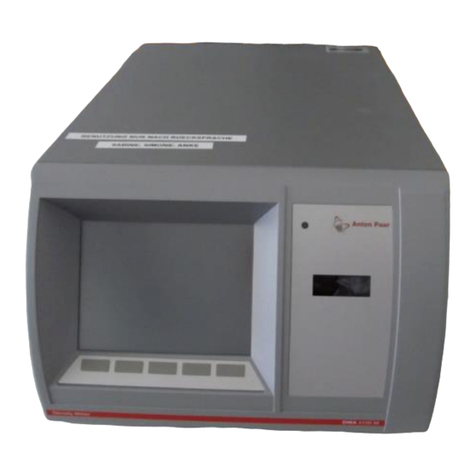
Anton Paar DMA 4100 M User manual

Measure
what is measurable
and make measurable
that which is not.
Galileo Galilei (1564-1642)
Instruction Manual
DMA 4100 M
DMA 4500 M
DMA 5000 M
instrument software version: from 2.70
(original instruction)


Instruction Manual
DMA 4100 M
DMA 4500 M
DMA 5000 M
instrument software version: from 2.70
(original instruction)

Disclaimer
This document may contain errors and omissions. If you discover any such errors or if you would like to see
more information in this document, please contact us at our address below. Anton Paar assumes no liability
for any errors or omissions in this document.
Changes, copyright, trademarks etc.
This document and its contents may be changed or amended by Anton Paar at any time without prior notice.
All rights reserved (including translation). This document, or any part of it, may not be reproduced, changed,
copied, or distributed by means of electronic systems in any form (print, photocopy, microfilm or any other
process) without prior written permission by Anton Paar GmbH.
Trademarks, registered trademarks, trade names, etc. may be used in this document without being marked
as such. They are the property of their respective owner.
Further information
Published and printed by Anton Paar GmbH, Austria
Copyright © 2015 Anton Paar GmbH, Graz, Austria
Address of the instrument producer: Anton Paar GmbH
Anton-Paar-Str. 20
A-8054 Graz / Austria – Europe
Tel: +43 (0) 316 257-0
Fax: +43 (0) 316 257-257
E-Mail: [email protected]
Web: www.anton-paar.com
Date: 04 August 2015
Document number: C76IB003EN-N

C76IB003EN-N 5
Contents
1 About the Instruction Manual ................................................................................................................ 7
2 Safety Instructions.................................................................................................................................. 8
3 Measuring Principle.............................................................................................................................. 10
4 The Instrument – Overview.................................................................................................................. 11
5 Checking the Supplied Parts ............................................................................................................... 12
6 Functional Components....................................................................................................................... 15
6.1 View of the Front and Right Side .................................................................................................... 15
6.2 View of the Left Side ....................................................................................................................... 15
6.3 Rear View ....................................................................................................................................... 16
6.4 Operating Elements on the Main Screen ........................................................................................17
6.5 Operating Elements on the Menu Screen....................................................................................... 19
7 Installing the Instrument ...................................................................................................................... 20
7.1 The Right Place .............................................................................................................................. 20
7.2 Mounting the Injection Adapters ..................................................................................................... 20
7.3 Checking for Leak Tightness .......................................................................................................... 21
7.4 Mounting the Hoses ........................................................................................................................ 21
7.5 Switching the Instrument On/Off ..................................................................................................... 22
7.6 Instrument Settings and First Checks ............................................................................................. 22
8 Checking, Adjusting, and Calibrating................................................................................................. 23
8.1 Definitions ....................................................................................................................................... 23
8.2 Checks ............................................................................................................................................ 23
8.2.1 Editing the Check Settings...................................................................................................... 23
8.2.2 Performing Density Checks .................................................................................................... 24
8.2.3 Viewing, Printing, or Exporting Current Check Data............................................................... 25
8.3 Adjustments .................................................................................................................................... 26
8.3.1 Performing an Air/Water Adjustment ...................................................................................... 26
8.3.2 Performing a Temperature Range Adjustment ....................................................................... 27
8.3.3 Performing a High Density/High Viscosity Adjustment (DMA 5000 M only) ........................... 27
8.3.4 Performing an Atmospheric Pressure Sensor Adjustment ..................................................... 28
8.3.5 Performing Special Adjustments.............................................................................................28
8.3.5.1 Special Adjustments ....................................................................................................... 28
8.3.5.2 Special Adjustment for the Canadian Excise Alcohol Table ........................................... 29
8.3.6 Viewing, Printing or Exporting Adjustment Data ..................................................................... 29
8.3.7 Viewing, Printing or Exporting Adjustment History: KB Graph................................................ 30
8.3.8 Resetting the Adjustment Data to Factory Adjustment ........................................................... 30
8.3.9 Adjustment Analysis ............................................................................................................... 30
8.4 Calibrating....................................................................................................................................... 31
9 Defining and Using Methods ............................................................................................................... 32
9.1 Measuring Methods ........................................................................................................................ 32
9.2 Changing Methods.......................................................................................................................... 33
9.2.1 Defining the Measurement Settings of the Density Module.................................................... 33
9.2.2 Defining the Measurement Mode............................................................................................ 34
9.2.2.1 Defining Formula Parameters......................................................................................... 36

6C76IB003EN-N
10 Measuring............................................................................................................................................ 37
10.1 Sample Name ............................................................................................................................... 37
10.2 Filling Samples.............................................................................................................................. 37
10.3 Performing Measurements............................................................................................................ 39
10.4 Filling and Measurement Errors .................................................................................................... 40
10.4.1 Status Messages .................................................................................................................. 40
10.4.2 Error Messages..................................................................................................................... 40
11 Cleaning and Storing the Instrument................................................................................................41
11.1 Cleaning and Drying the Measuring Cell ......................................................................................41
11.2 Storing the Instrument................................................................................................................... 42
11.3 Cleaning the Instrument Housing and Touch Screen ................................................................... 42
11.4 Repair ........................................................................................................................................... 42
Appendix A: Technical Data.................................................................................................................... 43
A.1: Measuring Performance ................................................................................................................ 43
A.2: General Technical Data ................................................................................................................. 44
A.3: Wetted Parts.................................................................................................................................. 45
Appendix B: Measuring Special Samples.............................................................................................. 46
B.1: Degassing Samples....................................................................................................................... 46
B.2: Special Filling Techniques............................................................................................................. 46
Appendix C: Measuring under Special Conditions............................................................................... 48
C.1: Measuring at High Humidity/Low Temperature Conditions ........................................................... 48
C.2: Measuring at Low/High Temperatures ..........................................................................................49
C.3: Measuring at High Pressures ........................................................................................................ 50
Appendix D: Camera Settings................................................................................................................. 51
D.1: Adjusting the Camera Position ...................................................................................................... 51
D.2: Setting the Camera Illumination .................................................................................................... 51
D.3: Saving a Camera Picture .............................................................................................................. 51
Appendix E: Trouble Shooting ............................................................................................................... 52
Appendix F: Output Quantities and Live Raw Data.............................................................................. 55
F.1: Output Quantities........................................................................................................................... 55
F.2: Live Raw Data ............................................................................................................................... 61
Appendix G: List of Quick Settings Parameters...................................................................................62
Appendix H: Density Tables.................................................................................................................... 64
Appendix I: Instrument Software Versions............................................................................................67
Appendix J: Calibration Approval .......................................................................................................... 71
Appendix K: Declaration of Conformity................................................................................................. 72
Appendix L: Menu Tree ........................................................................................................................... 73

1 About the Instruction Manual
C76IB003EN-N 7
1 About the Instruction Manual
This instruction manual informs you about the
installation and the safe handling and use of the
product. Pay special attention to the safety
instructions and warnings in the manual and on the
product.
The instruction manual is a part of the product. Keep
this instruction manual for the complete working life
of the product and ensure that it is easily accessible
for all people involved with the product. If you
receive any additions to or revisions of this
instruction manual from Anton Paar GmbH, these
must be treated as part of the instruction manual.
Conventions for safety messages
The following conventions for safety messages are
used throughout this instruction manual:
TIP: Tip gives extra information about the situation
at hand.
Typographical conventions
The following typographical conventions are used
throughout this instruction manual:
DANGER
Danger indicates a hazardous situation which, if
not avoided, will result in death or serious injury.
WARNING
Warning indicates a hazardous situation which, if
not avoided, could result in death or serious
injury.
CAUTION
Caution indicates a hazardous situation which, if
not avoided, could result in minor or moderate
injury.
NOTICE
Notice indicates a situation which, if not avoided,
could result in damage to property.
Convention Description
<key> The names of keys and
buttons are written between
angle brackets.
menu level 1 >
menu level 2
Menu paths are written in
italics. Menu levels are
connected by a closing
angle bracket.

2 Safety Instructions
8C76IB003EN-N
2 Safety Instructions
• Read this instruction manual before using the
instrument.
• Make this instruction manual easily accessible
to all persons working with the instrument.
• Follow all hints and instructions in this instruc-
tion manual to ensure the correct use and safe
functioning of the instrument.
2.1 Liability
• This instruction manual does not claim to
address all safety issues associated with the
use of the instrument and samples. It is your
responsibility to establish health and safety
practices and to determine the applicability of
regulatory limitations.
• Anton Paar GmbH warrants the proper
functioning of the instrument only if no
modifications are made to mechanics,
electronics, module firmware, or instrument
software.
• Use the instrument only for the purpose
described in the instruction manual. Anton Paar
GmbH is not liable for damages caused by
incorrect use of the instrument.
• The results delivered by the instrument depend
not only on the correct functioning of the
instrument but also on various other factors. We
therefore recommend that you have the results
checked (e.g. plausibility tested) by skilled
personnel before consequential actions are
taken based on the measured data.
2.2 Installation and Use
• The installation procedure shall be carried out
only by authorized personnel who are familiar
with the installation instructions.
• Use only accessories or consumables supplied
or approved by Anton Paar GmbH.
• Ensure that all operators have been trained
beforehand to use the instrument safely and
correctly.
• Ensure that the instrument is sufficiently
supervised during operation.
• In case of damage or malfunction, do not
continue operating the instrument. Do not
operate the instrument under conditions which
could result in damage to goods or injuries or
loss of life.
• If liquid has been spilled over the instrument,
disconnect the instrument from the mains
supply. Clean and dry the housing of the
instrument. If you have a suspicion that liquid
got into the instrument, have the instrument
cleaned and checked for electrical safety by a
service technician.
Operation in areas with risk of explosion
• The instrument is not explosion-proof and
therefore must not be operated in areas with risk
of explosion.
General precautions
• Observe and adhere to your national safety
regulations regarding the handling of all
substances associated with your measurements
(e.g. use safety goggles, gloves, respiratory
protection, etc.).
• Before a measurement, check the wetted parts
of the instrument for chemical resistance to the
samples and cleaning agents used.
• Take care that the liquids (samples and cleaning
agents) or gases that you use are chemically
compatible when they come into contact with
each other. They shall not react exothermally or
produce solid particles which might stick to the
inner walls of the measuring cells.
• Before you start a measurement or cleaning
procedure, take care that all parts, especially
the measuring cells, the injection adapters, the
hoses, and the waste vessel, are properly
connected and in good condition.
• Before you start a measurement or cleaning
procedure, check the injection adapters for leak
tightness.
• Take measures that spilled liquids cannot get
into plug connections or venting slots of
electrical appliances.
• Connect the measuring system to the mains
supply via a safety switch located at a safe
distance from the instruments. In an emergency,
turn off the power using this switch instead of
the power switch on the instruments.
2 Safety Instructions
C76IB003EN-N 9
Precautions for flammable samples and
cleaning agents
• Keep potential sources of ignition, like sparks or
open flames, at a safe distance from the
instrument.
• Place the instrument on a laboratory bench
made of fireproof material, preferably bricks,
ceramics, or stoneware.
• Store only the minimum required amount of
sample, cleaning agents, and other flammable
materials near the instrument.
• Do not spill sample/cleaning agents or leave
their containers uncovered. Immediately remove
spilled sample/cleaning agents.
• Ensure that the setup location is sufficiently
ventilated. The environment of the instrument
must be kept free of flammable gases and
vapors.
• Provide fire-extinguishing equipment.
Transport
• Empty the measuring cell and all hoses before
you move or lift the instrument.
• To move or lift the instrument, grasp the ledge
on top of the instrument’s back side with one
hand. Place the other hand under the display on
the front side. There is a hollow for your fingers.
• Carry the instrument in front of you and keep it
close to your body.
2.3 Maintenance, Service, Repairs
• Service and repair procedures may be carried
out only by authorized personnel or by Anton
Paar GmbH.
• For repairs, contact your local Anton Paar
representative. The instrument must not be
returned without the filled out "Safety
Declaration for Instrument Repairs" and must be
cleaned before return.
• You must not return instruments which are
contaminated by radioactive materials,
infectious agents, or other harmful substances
that cause health hazards.
2.4 Disposal
• Concerning the disposal of the instrument,
observe the legal requirements in your country.

3 Measuring Principle
10 C76IB003EN-N
3 Measuring Principle
Definition of density and specific gravity
The density ρof a sample is defined as mass
divided by volume:
The specific gravity SG is calculated by dividing the
density of a sample by the density of pure water at
20 °C:
Density and Specific Gravity values are highly
temperature-dependent.
The oscillating U-tube method
The sample is introduced into a U-shaped
borosilicate glass tube that is being excited to
vibrate at its characteristic frequency. The
characteristic frequency changes depending on the
density of the sample. Through a precise
determination of the characteristic frequency and a
mathematical conversion, the density of the sample
can be measured.
The density is calculated from the quotient of the
period of oscillations of the U-tube and the reference
oscillator:
Concentration measurement
In binary mixtures, the density of the mixture is a
function of its composition. Thus, the density value
of a binary mixture can be used to calculate its
composition with the aid of density/concentration
tables.
This is also possible with so-called quasi binary
mixtures. These are mixtures containing two major
components and some additional components
which are present in very small concentrations
compared to the two main components. Many
decarbonated soft drinks, for example, can be
considered to be quasi binary solutions of sugar in
water because the concentration of flavors and
acids are very small compared to sugar and water.
Thus, the sugar concentration can be measured
with a density meter.
Note that the accuracy of the concentration
measurement depends not only on the accuracy of
the instrument, but also on the slope of the
density/concentration correlation. This means, for
example, that a density measurement with an
accuracy of ±0.00001 g/cm3will be converted into
an ethanol value with a significantly smaller
accuracy of ±0.025 % w/w. The accuracy of some
typical concentration measurements is given in
appendix A.1.
KA, KB .... apparatus constants
Q ............. oscillation period of the U-tube divided by
the oscillation period of the reference
oscillator
f1, f2........ correction factors for temperature,
viscosity, and nonlinearity
m
V
-----
=
SG Sample
Water
--------------------
=
density KA Q2f1KB f2
–=

4 The Instrument – Overview
C76IB003EN-N 11
4 The Instrument – Overview
The density and concentration meters of the DMA M
series have been developed to combine highest
precision with easy operation and robust design.
Measurement is based on the oscillating U-tube
method that has been invented at a research
institute in Graz, Austria, and first introduced onto
the market by Anton Paar in 1967.
Features and Benefits
Accuracy
Your DMA M series instrument is equipped with the
world’s most advanced digital density measurement
technology:
• The period of oscillation of the U-tube is
measured by optical pickups.
• Two integrated Pt 100 platinum thermometers
together with Peltier elements provide an
extremely precise thermostatting of the sample.
• ThermoBalance™: An additional reference
oscillator provides long-term stability and
enables precise measurements over the whole
temperature range of the instrument with only
one adjustment at 20 °C.
• Viscosity-related errors are automatically
corrected over the full viscosity range by
measuring the damping effect of the viscous
sample which is subsequently taken account of
in the calculation of the definitive density value.
• With DMA 5000 M, the precision for samples
with high viscosity and high density can be
increased by special adjustments with
standards of high viscosity and high density.
• The built-in atmospheric pressure sensor
enables correct air adjustment, as the air
density is dependent on the atmospheric
pressure.
Error detection
A major source of measuring errors with density
meters are gas bubbles in the measuring cell. This
issue is addressed by Anton Paar with two new
features:
• FillingCheck™: The instrument automatically
detects inhomogeneities and gas bubbles in the
whole measuring cell by an advanced analysis
of its oscillation pattern. Where necessary, a
warning message is generated in real time for
every single measurement.
• U-View™: Real-time images by a camera with
zoom function enable you to visually inspect the
measuring cell.
User interface
The touch screen user interface facilitates easy and
intuitive operation in routine applications as well as
in demanding scientific research work:
• For the most common applications, 10
measuring methods are predefined. Just select
the method fitting your application, or create
your own methods.
• Density values are automatically converted into
concentration values for a large number of
factory-programmed substances. You can add
further substances as required by yourself.
• Optionally operate DMA 4100/4500/5000 M via
external keyboard, mouse, or bar code reader.
• Optionally connect an external monitor or touch
screen (VGA interface).
Compact and robust design
The instruments of the DMA M series keep up the
tradition of the legendary previous DMA generations:
• Compact design
• Sealed housing
• Robust housing materials: coated aluminum
(top and sides), aluminum (base and back), and
polystyrene/butadiene (front)

5 Checking the Supplied Parts
12 C76IB003EN-N
5 Checking the Supplied Parts
DMA 4100/4500/5000 M has been tested and
packed carefully before shipment. However,
damage may occur during transport.
1. Keep the packaging material (box, foam piece,
transport protection) for possible returns and for
further questions from the transport or insurance
company.
2. Check the delivery for completeness by
comparing the supplied parts to those listed in
table 5-1.
3. If a part is missing, contact your Anton Paar
representative.
4. If a part is damaged, contact the transport
company and your Anton Paar representative.
Table 5-1: Supplied parts
Symbol Pcs. Article description Mat. no.
1 DMA 4100 M
DMA 4500 M
DMA 5000 M
153058
153059
153060
1 Power cord
Europe
or USA
or UK
or Thailand
65146
52656
61865
79730
1 Instruction manuals English
• Instrument
• General Software Functions
or
Instruction manuals German
• Instrument
• General Software Functions
80812
135322
87090
135321
1 Density standard ultra-pure water 5x10 mL with
certificate
96044
1 Waste vessel 500 mL 6210

5 Checking the Supplied Parts
C76IB003EN-N 13
1 Accessory kit DMA / DMA M 159958
containing:
2 m Hose 3x5 mm silicone (transparent)
only for pressures up to 0.4 bar rel.
50814
7 Syringe 2 mL Luer 51974
2 Injection adapter Luer black 159026
2 Male Luer plug PTFE 63865
3 Adapter Luer cone PTFE
only for pressures up to 0.4 bar rel.
63863
1 Adapter UNF 1/4″Luer male 64793
1 Hose clamp 21531
1 Phillips screwdriver PH-0x40 75030
Table 5-1: Supplied parts
Symbol Pcs. Article description Mat. no.

5 Checking the Supplied Parts
14 C76IB003EN-N
Table 5-2: Optional parts
Article description Mat. no.
Data handling
Keyboard German USB 80809
Keyboard USA USB 80807
Printer RS-232C incl. cable 9600N81 44737
Printer Epson TM-U220D 93362
RS-232 connection cable D-Sub 9-pin, 3 m 70429
Gender changer DB9M/DB9M 302592
Automatization
Sample changer Xsample 122 46534
Sample filling unit Xsample 22 81340
Sample changer Xsample 452 46535
Sample changer Xsample 530 105700
Filling and rinsing unit Xsample 352 81338
Sample handling unit Xsample 52 81339
Heated sample changer Xsample 452 H 84806
Heated filling and rinsing unit Xsample 352 H 84808
Protection
Protecting cover for keyboard 13350
Protection cap for USB interfaces 156194
Special funnel protection 82448
Special application accessories
Aerosol adapter 74650
Cooling kit DMA M 80810
Drying cartridge (with silica gel) 65085
Heating attachment for DMA M 83161
Syringes
Syringe 2 mL Luer (1 pc.) 51974
Syringes 2 mL Luer (10 pcs.) 58802
Syringes 2 mL Luer (1000 pcs.) 66399
Syringes 5 mL Luer (100 pcs.) 6772

6 Functional Components
C76IB003EN-N 15
6 Functional Components
6.1 View of the Front and Right Side
Fig. 6-1: View of the front and right side of the DMA M
6.2 View of the Left Side
Fig. 6-2: View of the left side
1 Power on LED
2 Color PCAP touch screen
3 Xsample slot cover plate
4 Sample inlet and outlet
5 Air pump outlet
2
1
3
4
5
1 Blind covers for inlet and outlet of the optional cooling kit
2 USB interfaces
3 Protection cover for the USB interfaces
123

6 Functional Components
16 C76IB003EN-N
6.3 Rear View
Fig. 6-3: Rear view
1 S-BUS interfaces
2 USB interface
3 VGA interface
4 RS-232 interface (COM)
5 Ethernet interface
6CANinterface
a
7 "DRY AIR IN AIR PUMP" connector
8 "DRY AIR IN BLOCK" connector
a for the connection of further measuring modules
9 Power switch
10 Fuse holder
11 Power inlet
12 UL test mark
13 Type plate with serial number
14 Fan
15 Carrying ledge
12
3
4
5
6
7
8
91011
14
15
1213

6 Functional Components
C76IB003EN-N 17
6.4 Operating Elements on the Main Screen
Fig. 6-4: Main screen example
Header
On the left side of the header, you find the name of
the currently active method and the sample number.
On the right side of the header, you find a clock and
the user indicator. The user indicator indicates the
type of user that is currently logged on.
Content area
In the content area, the measuring values are
displayed in small, medium, or large output fields.
The layout of the content area can be defined in the
settings of the current method according to your
needs.
The progress bar at the bottom of the content area
indicates whether the instrument is currently
measuring or whether a measurement has finished.
Monitor mode
If you have not started a measurement yet, or if you
have terminated a measurement by tapping <Stop>,
the instrument is in the monitor mode and shows a
continuous reading of the current measuring values.
Measuring mode
If you have started a measurement, a continuous
reading of the current measuring values is shown
until the measurement is finished. The final values
stay frozen on the screen until the next
measurement is started. To unfreeze the screen
and change to monitor mode, tap in the quick
access area.
Buttons area
The buttons on the main screen have the following
functions:
1 Header
2 Output field
3 Content area
4 Progress bar
5 Buttons area
6 Quick access area
1
2
3
4
5
6
Button Function
<Menu> Opens the main menu
<Quick Settings> Opens the quick settings list
(only available in the "No
Sample List" mode instead
of the <Sample List> button)
<Sample List> Opens the current sample
list
<Method> Opens the method list (to
select a method)
<Start> Starts a measurement
<Stop> Stops and aborts a
measurement

6 Functional Components
18 C76IB003EN-N
Quick access area
Fig. 6-5: Expanded quick access area
• To expand the quick access area, tap the
icon on the quick access bar on the main
screen.
• To collapse the quick access area, tap the
icon in the upper right corner of the expanded
quick access area.
• To browse items, use the page navigation
in the header of the expanded
quick access area.
• To rearrange the items in the quick access area,
tap (settings) in the upper left corner of the
expanded quick access area. For details, see
the General Software Functions Manual,
section 4.8.
Function
Opens the message list.
The general instrument status as well as
all measuring errors that have occurred
during the measurements of the currently
active sample list are described in this list.
The button changes its appearance
depending on the current error status:
Green OK sign:
The general instrument status and the
error status of all measured samples of
the current sample list are OK.
Yellow warning sign:
• The instrument (or system) has a minor
problem (e.g. an air or water check is
overdue, there is a printer problem etc.).
• There has been a filling error with one or
more samples of the currently active
sample list.
Red error sign:
• The instrument (or system) has a major
problem that needs to be fixed before
you continue with measurements
(e.g. the sample changer is blocked).
• One or more samples of the current
sample list could not be measured (e.g.
the measuring cell is partly empty so
that it cannot oscillate).
To reset the message list button to the
green OK sign, confirm all error messages
by tapping on the <X> button on the right
side of the message. To confirm all
messages in the list in one step, tap
"Delete all" at the end of the list.
The message list button will also be reset
to the green OK sign if you delete the
currently active sample list, see General
Software Functions Manual, section 7.6.
U-View™: Opens the live camera view of
the measuring cell.
Starts/stops the air pump.
The air pump is off.
The air pump is on.
Unfreezes the screen after a finished
measurement.
The screen is frozen.
The screen is unfrozen. A continuous
reading of the current measuring values is
shown.
Displays information on using favorites.

6 Functional Components
C76IB003EN-N 19
6.5 Operating Elements on the Menu Screen
To access the menu, tap <Menu> on the main screen.
Fig. 6-6: Menu screen examples
Header
On the left side of the header, you find the
navigation path to your current position in the menu.
You can go back to any menu position in your
current path by directly tapping on the respective
box of the navigation path. For details on using the
<Add to Favorites> button, see the General
Software Functions Manual, section 4.8.
Content area
In the content area, you find the menu options of the
current menu level and the menu dialogs.
Buttons area
The buttons on menu screens have the following
functions:
A1 Header
A2 Menu level 1
A3 <Back> button
A4 <Home> button
A5 Content area
B1 <Add to Favorites> button
B2 Buttons area
B3 Content area
A1
A2
A3
A4
A5
B2
B1
B3
Button Function
<Back> Moves to the next higher menu
level.
<Home> Returns to the main screen.
Buttons at
the bottom of
screens
Functions depending on the
current menu or dialog

7 Installing the Instrument
20 C76IB003EN-N
7 Installing the Instrument
To install the instrument, put it on a bench, mount
injection adapters and hoses, and connect the
instrument to the mains supply. Define general
instrument settings and perform an air/water check
to check the validity of the factory adjustment.
For the installation of an Xsample filling module, see
the respective instruction manual.
7.1 The Right Place
DMA 4100/4500/5000 M is designed for operation
under typical laboratory bench top conditions.
To guarantee temperature stability, do not place the
instrument:
• near a heat source
• in a drafty place (e.g. near an air conditioner)
• on a vibrating surface or close to vibrating
equipment
• in direct sunlight
7.2 Mounting the Injection Adapters
1. Take two injection adapters Luer with screws
from the accessory kit.
2. Pull out the black plastic transport plugs from
the tips of the injection adapters.
TIP: Keep the plastic transport plugs for later use.
They can be used as an injection adapter tool to
widen the tips of the adapters in case of leaks.
Fig. 7-1: Mounting the injection adapters Luer
3. Carefully insert the injection adapters into the
openings of the adapter holding plate on the
right side of the instrument, see Fig. 7-1.
4. Push both adapters towards the holding plate
with moderate force.
5. Insert the screws through the bore holes of the
adapters and screw them cautiously into the
adapter holding plate until some resistance
against further turning can be felt.
WARNING
Using hazardous or flammable chemicals as
samples or cleaning liquids could lead to
damage of the instrument and cause serious
injuries unless special precautions are taken.
• Observe the safety instructions in the section
"Special precautions for flammable chemicals"
in section 2.
NOTICE
• Ensure that the power plug and the power
switch are always easily accessible so that the
instrument can be easily disconnected from
the mains supply at any time.
• A strong built-in cooling fan dissipates heat
through the bottom and the rear of
DMA 4100/4500/5000 M. Ensure that the air
flow is not blocked, and provide for a minimum
distance of 10 cm (4 in) to walls behind and
beside the instrument.
• High humidity or a measuring temperature that
is significantly below the ambient temperature
may lead to condensation within the
measuring cell. Install a drying cartridge to
avoid condensation, see appendix C.1.
CAUTION
If the screw for fastening the adapter is
overtightened, the density measuring cell may
be damaged. Harmful liquids leaking from the
instrument may cause injuries.
• Tighten the screw until some resistance
against further turning can be felt, and then
stop to tighten the screw.
The gap left between the holding plate and the
adapter, where the thread of the screw can be
seen, is approx. 3–8 mm (approx.
0.12–0.31 in).
Other manuals for DMA 4100 M
2
This manual suits for next models
2
Table of contents
Other Anton Paar Measuring Instrument manuals

Anton Paar
Anton Paar SVM 2001 Original instructions

Anton Paar
Anton Paar DMA 35 Manual

Anton Paar
Anton Paar ViscoQC 300 Series Original instructions

Anton Paar
Anton Paar DMA 35N User manual

Anton Paar
Anton Paar DMA 35 Manual

Anton Paar
Anton Paar DMA 4100 M Original instructions

Anton Paar
Anton Paar SmartRef Original instructions

Anton Paar
Anton Paar DMA 4100 M User manual

Anton Paar
Anton Paar TCU 1000 User manual

Anton Paar
Anton Paar PA 5 User manual