AON Inni-Robo User manual

INNI-ROBO_USER MANUAL_191225PS
User Manual
BIO-CERAMIC DLP 3D PRINTER
INDUSTRIAL

2
TABLE OF
CONTENTS
Chapter 1 Safty Precautions 3
Chapter 2
Introduction to INNI-ROBO 3D Printer (ACP-M11B)
4~8
What is INNI-BORO 3D Printer?4
Special features 5
List of components 6~7
Accssories 8
Chapter 3 INNI-ROBO 3D Printer Usage Guide 9~23
Setting Up the Printer 10~13
Setting Up the Network 14~15
Using the Slicer Program 16~17
Using the Touch Screen Functions 18~23
Software & Firmware Update 23
Chapter 4 Troubleshooting 24
Chapter 5 Product Specifications 25
Chapter 6 Product Warranty 26~27
2

3
INNI-ROBO_USER MANUAL_191225PS
※Please follow safety instructions at all times.
Read the following precautions carefully and familiarize yourself with the INNI-ROBO 3D Printer User
Manual before setting up and using the printer. Failure to comply with the given warnings can lead to
serious injury, fire, or equipment and/or property damage.
•Make sure that the printer and all accessories are physically intact and free of damage.
•Do not destroy or alter the printer’s power cable. Use the proper voltage (220V) when connecting to a power
source.
•Parts of the printer have sharp edges/corners. Be careful to avoid injury or printer damage when using.
•Do not place a foreign object inside the printer as this will incur the risk of injury or property damage.
•Select the installation site carefully to avoid causing injury to children or pets.
•Avoid operating the printer with wet or dirty hands as the introduction of water or other foreign liquid to the printer’s
metal and other conductive surfaces can cause fire or electric shock.
•Do not install the printer outdoors or in an area that is poorly ventilated, humid, or dusty.
•Do not disassemble or alter the printer except as specified in the operation manual since doing so may cause user
injury and/or printer damage. Any such problem will not be covered under warranty.
1. Safety Precautions

4
2. Introduction to INNI-ROBO 3D Printer
2. Introduction to INNI-ROBO 3D Printer (ACP-M11B)
INNI-ROBO 3D Printer is especially designed to produce artificial teeth.
Using ROBO-ICM (ICM-W500), a zirconia slurry designed exclusively for INNI-ROBO 3D Printer, and digital
light processing, any industrial configuration can be recreated before your very eyes, one layer at a time.
A 7-inch color touch screen is provided at the front of the printer for easier use.
Smart, comfortable design
Introduction to INNI-ROBO 3D Printer (ACP-M11B)

5
INNI-ROBO_USER MANUAL_191225PS
One star feature of INNI-ROBO 3D Printer is its automatic bed leveling
function, which allows for hassle-free operation and precision.
Automatic leveling function
Special features
Another key feature of INNI-ROBO 3D Printer is the special modeling bed film that makes up the base of the
modeling bed. Detachable and reversible, it allows for optimized light refraction to achieve higher durability in the
printed output and is designed to release the finished product cleanly and easily.
3D Modeling Bed Film
* For film exchange or install the modeling bed,
please refer to the video. www.aoninni.com
Modeling bed
Modeling bed flim
Modeling bed
bracket
Bracket bolts
Build platform
Liquid zirconia material designed to be used exclusively by INNI-ROBO 3D
Printer.
* Important note : For the shrinkage percentage, please refer to the label
on the bottle.
Zirconia slurry (ROBO-ICM)

6
2. Introduction to INNI-ROBO 3D Printer
NO Name Description
1LCD console LCD touch screen panel
2Power button Power switch next to the LCD console
3Main door Outward swinging door; blocks UV rays during printing
4USB ports Connection for a USB memory stick or external hard drive
5Ethernet port Connection for a computer (recommended)
6Main power switch Main switch for the power source to the printer
7Power socket 220V connection socket
8Handle Used for lifting and moving the printer
9Air vents Ventilation openings
10 Main door panel For viewing the printing process
Outer components
③
Main door
①
LCD console
⑩
Main door panel
⑨
Air vents
⑦
Power socket
⑥
Main power
switch
⑤
Ethernet port
⑧
Handle
②
Power button
④
USB ports
List of components

7
INNI-ROBO_USER MANUAL_191225PS
NO Name Description
1LM GUIDE Guide for the z-axis stage
2Knob-L30 Fixture for the build platform
3Blade support Attachment support for the mixing blade
4Knob-Blade Fixture for the mixing blade
5Blade For the mixing the slurry inside the modeling bed
6Modeling bed Container for the slurry
7VR15 Leveler for the printer
8Knob-L15 Fixture for the platform plate
9Ball screw Controller for the z-axis stage
10 Z-axis main stage arm Attachment support for the build platform using Knob-L30
11 Z-axis stage Connecting stage between the LM guides and ball screw
12 Knob-L20 Fixture for the modeling bed
Internal components
①LM GUIDE
② Knob-L30
⑦ VR15
⑥ Modeling bed
⑤ Blade
④ Knob-Blade
③ Blade support
⑧ Knob-L15
⑨ Ball screw
⑩ Z-axis main
stage arm
⑪ Z-axis stage
⑫ Knob-L20

8
2. Introduction to INNI-ROBO 3D Printer
Item Product code Item Product code
Scraper
Used to detach the printed
model moldings
AS11-1001P
Modeling bed lm
spares
(10 total)
AS11-1001P
ROBO-ICM
Zirconia slurry for
INNI-ROBO 3D Printer use
ACP11-10001Y Power cable
Main power cord ACP11-10001Y
Build platform AB11-40000A
Ethernet cable
Used to connect a computer
to INNI-ROBO 3D Printer
AB11-40000A
Item Item
Safety glasses
Protection for the eyes
Hex key (2.5mm)
Used to change
the modeling bed film
Latex gloves
Protection for the hands
Sprayer
Used to clean the build
platform/modeling bed
Spatula
Used for mixing
Hex key (3.0mm)
Used to attach/detach
the main door of the printer
Nipper
Used to remove
the support on the printed output
Sieve
Used to filter out residue
* To purchase, please contact AON Call Center at (+82 70 4304 4996).
The following is a list of the accessories included with product purchase. This list is subject to change without notice.
See homepage (http://www.aoninni.com) for additional purchase options.
Accessories (included)
The following is a list of the extra accessories available for INNI-ROBO 3D Printer.
Accessories (for purchase)
2.5mm
3.0mm
Accesories

9
INNI-ROBO_USER MANUAL_191225PS
3. INNI-ROBO 3D Printer Usage Guide
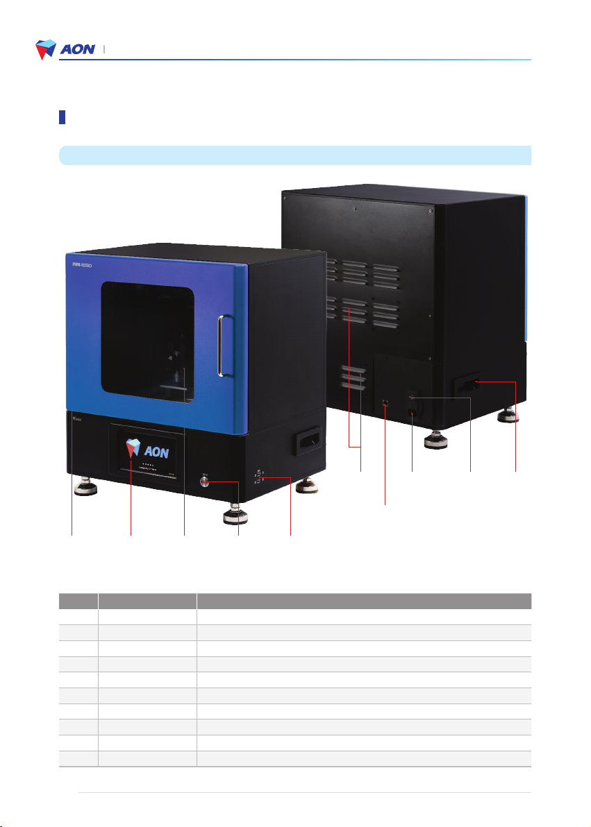
1) Please install the printer in a climate controlled environment (20-40°C) without exposure to water or direct sunlight.
Be sure to use the proper voltage (220V) and to flip the main power switch on the backside of the printer to the
ON position.
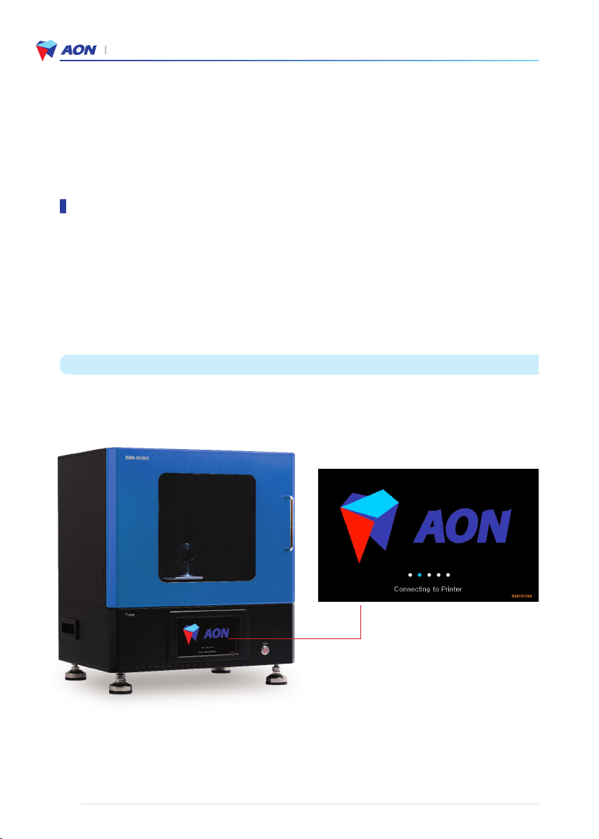
2) Locate the power button next to the LCD console on the front of the printer. Push this button for one or more
seconds until a click is heard. The touch screen panel will display AON’s logo upon start up.
Note: INNI-ROBO 3D Printer is only compatible with Windows 7 or higher.
3) Upload the printing file to Aon Slicer program as the form of a file (* .stl) for manufacturing industrial products with
INNI–ROBO 3D printers and ROBO-ICM (Zirconia slurry).
Note: To create or edit a printing file, you must use AON slicer software.
4) Set the layer thickness to 50μm and the curing conditions to 15 seconds.
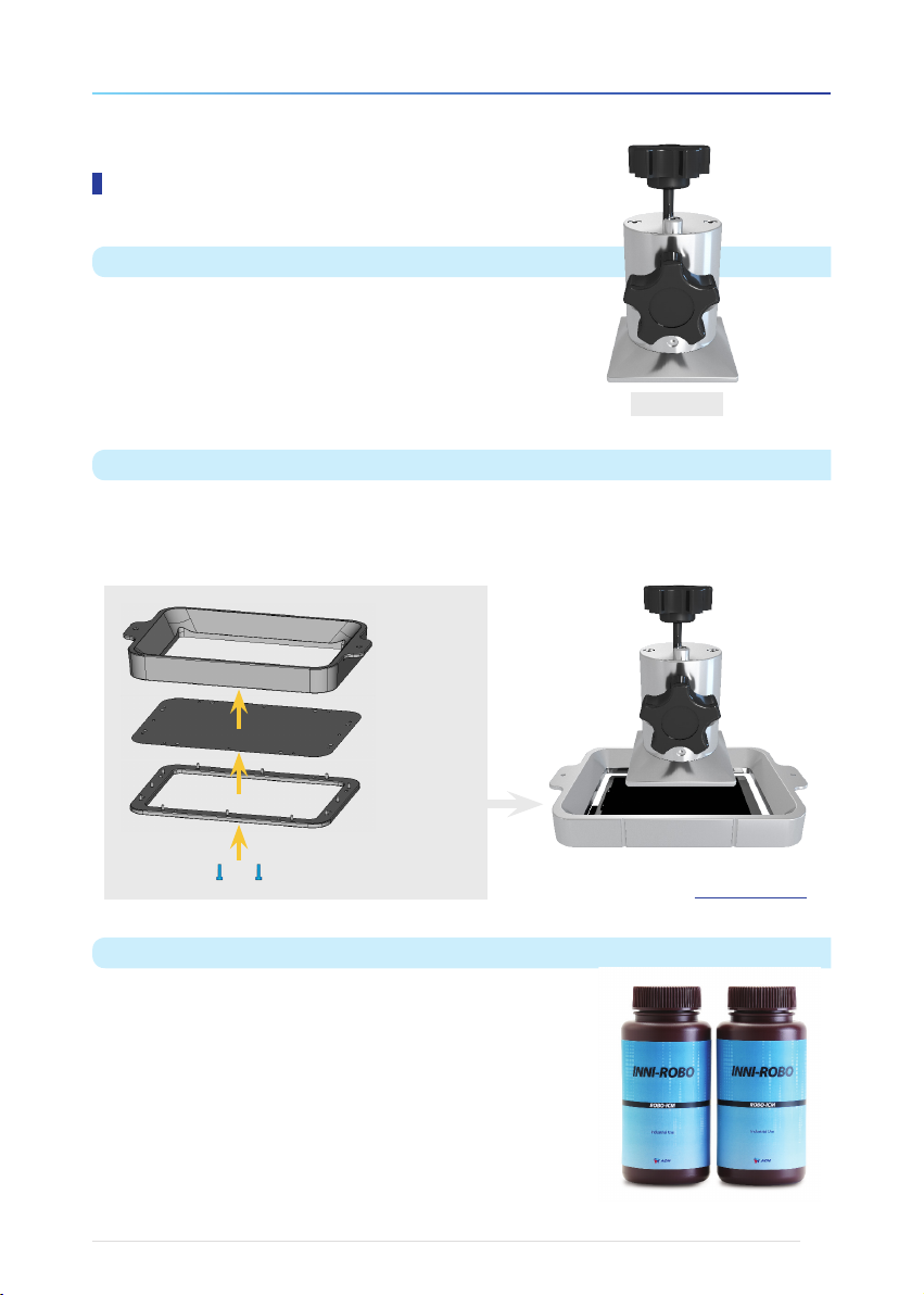
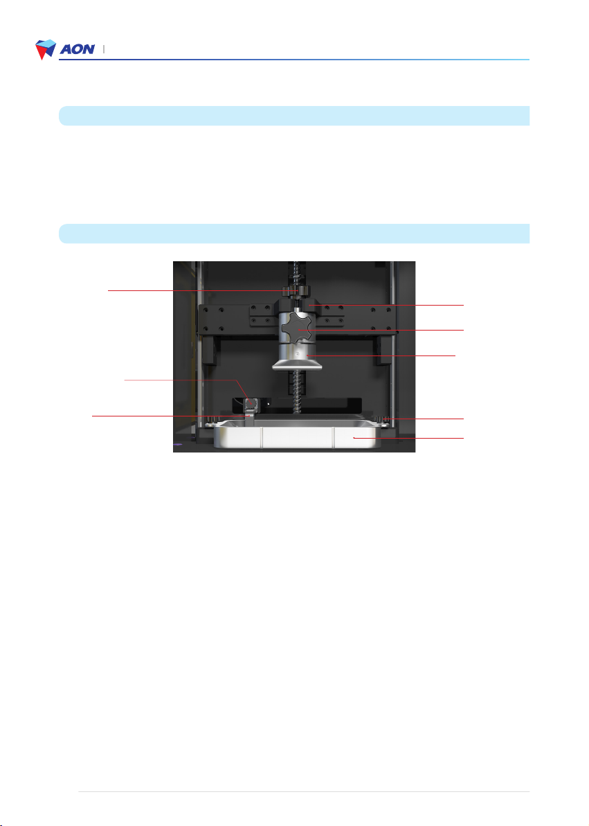
5) Add the zirconia slurry (ROBO-ICM) into the INNI-ROBO 3D Printer modeling bed and implement Preheat and
Blade Mixing before printing.
6) The build platform will lower, automatically adjusting to the correct height, and the 3D printing process will begin.
Layers (displayed as an image on the touch screen) are laminated one at a time and cured via UV LED light. This
laminating and curing process repeats until the industrial material shape specified for printing has been created.
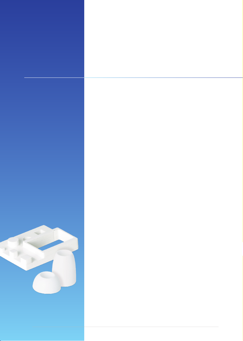
7) The printed output should detach easily from the base of platform plate. Remove the support that is attached
underneath and finish it off with a cleaning and final heat treatment, leaving just the solid material.
8) Printed productions made by INNI–ROBO 3D printers are used for cutting-edge industrial materials.
9) INNI-ROBO 3D Printer must use AON’s exclusive zirconia slurry ROBO-ICM to produce the desired industrial
materials. Using other products will cause damage to the printer in which case AON cannot be held responsible.
* Please refer to the video for more details. AON Call Center (+82 70 4304 4996)
* If you have further questions, contact our Call Center (+82 70 4304 4996) or send a message to our Support
Team (http://aoninni.com).
User Guidelines

10
3. INNI-ROBO 3D Printer Usage Guide
Confirm that the bottle of zirconia slurry is labeled ROBO-ICM.
1) Confirm that the printer looks intact and ready for use.
2) Open the bottle of zirconia slurry (ROBO-ICM) and check the contents for impurities.
Precautions
Pre-check before printing
1. Install the printer
1) Build platform
After loosening Top fixture (①KNOB-L30), attach the build platform to the platform holder (①-1 Z-AXIS MAIN
STAGE ARM)
2) Middle fixture (②KNOB-L15)
Loosen the middle fixture and check for suitable spring strength and operation
(Two full turns of the fixture should allow the platform plate to move easily in all directions).
* This is an important step prior to initiating preheat or blade mixing.
3) Modeling Bed : Assemble the modeling bed (③+③-1) to the printer
4) Blade : Assemble blade (④+④-1) to the modeling bed
2. Prepare printing - Zirconia slurry (ROBO-ICM)
1) Add Zirconia slurry at least 150g to the modeling bed.
2) Preheat : AON Slicer →Set up →Position control →Preheat 10min
* When preheat, a light will turn on inside the printer on the left side and platform moves to the home position.
* During the preheating process, do not use any other printer operation
3) Blade mixing : AON Slicer →Set up →Position control →Blade mixing
4) Touch screen of printer →Position control →Home position →Tighten the middle fixture (②KNOB-L15) →
Plates →Start print
* Please check that the middle fixture (②KNOB-L15) must be tightened before printing.
* Please refer to the video for more details. www.aoninni.com
① KNOB-L30
④ Blade
④ -1 KNOB-Blade
③-1 KNOB-L20
Platform plate
①-1 Z-AXIS MAIN
STAGE ARM
② KNOB-L15
③ Modeling bed

11
INNI-ROBO_USER MANUAL_191225PS
1. Plug in the power cable and connect to power source and flip the main power switch to ON [ I ].
2. Press the power button next to the touch screen console on the front of the printer for 3~4 sec.
Hold and wait for the AON logo to appear.
Checklist
• Make sure the power cable and plug are free from defect/damage before connecting.
• Make sure the plug outlet is clear of any debris before connecting the power cable.
• Avoid twisting or bending the power cable as much as possible.
• Do not turn off the printer while in operation as this may cause defective printer output and/or malfunction.
• To disconnect, pull on the main body of the plug, not on the cable.
Setting up the printer

12
3. INNI-ROBO 3D Printer Usage Guide
• Click to move the build platform into neutral position (zero).
• Use the arrows to check that the build platform moves up and down the z-axis.
3. Click the icon you are going to use.
※After 10 seconds has elapsed from the main screen, the screen moves to Home Position setting screen automatically.
4. Position Control screen
Home Position Setting
Setting up the printer

13
INNI-ROBO_USER MANUAL_191225PS
5. Check the file and print
Click Paltes from the main screen
After pressing the power button (ON/OFF) on the front of the printer, check that the AON screen turns off. (Press and
hold the power button for more than 3 seconds.)
※
If the back of the printer is powered on even after the screen is turned off, the front power button will flash red.
If you want to turn off the printer completely, flip the main power switch to ON [ O ] on the back.
Turning off the printer
• Plates screen
Choose file →Check model →Print
Do NOT turn off the printer while the printer is in operation.
• Choose the file to print

14
3. INNI-ROBO 3D Printer Usage Guide
Recommended : Use an Ethernet(Wired) connection when connecting the 3D printer and the PC.
• When connecting the 3D printer to the PC for the first time, make sure to use the Ethernet connection and you
may connect Wi-Fi additionally.
Precaution : Printer may have an error If Wi-Fi connection is lost or weak
6. Press the play button or ‘Connect’.
1.Press the wi-fi icon to begin. 2. Press on ‘Scan wifi’.
3. Choose an available wi-fi network. 4. Touch the blank to fill in the password.
5. Enter the password for the network.
Wired network connection (Ethernet)
Connect the cable to the Ethernet ports to
the PC and on the back of the printer.
For more details, please refer to P.17 in this
manual.
Wireless network connection (Wi-Fi)
Setting up the network (Access to AON Slicer)

15
INNI-ROBO_USER MANUAL_191225PS
1. Check via 3D printer
Touch Screen of the printer →Click WiFi icon
→Check IP address →Enter the IP Address
into a web browser
①Click Wi-Fi on the top right of the screen
③Confirm the Wi-Fi signal if connection is successfully made (See the image below).
2. Check via IP Scanner
Access to www.advanced-ip-scanner.com →
Download “Advanced IP Scanner” →Click “Scan” →
Find the IP Address which has the manufacturer “Raspberry
Pi Foundation” →Enter the IP Address into a web browser
②A list of networks will appear. Choose a network and
input the password. Click on the ‘Connect’ button.
※When entering the IP address in a web browser, do not enter the last two digits.
After connecting the printer and the PC, check the IP address, enter it into a web browser, and access AON Slicer
(Software).
Printer IP address
Wi-Fi connection on AON Slicer

16
3. INNI-ROBO 3D Printer Usage Guide
1. AON Web Browser :
Click on the ‘INNICERA Profile’ button to bring up the Settings page and check that the printer’s profile.
* DO NOT change these settings or else malfunction may occur.
2. Z-axis controls :
Click on " Setup", then " Position control". The following screen will appear.
A
C
B
Using the slicer program
Zone A
• Digitized distance of the z-axis
according to the current position of the
build platform
Zone B
• Preheat : Preheats the zirconia slurry
(ROBO-ICM) for viscosity control
• Blade : Controls the levelness and
viscosity of the zirconia slurry
• Home_position : Resets the position of
the build platform and modeling bed
• Emergency_Stop : Stops all operations
(turn the printer off and on again when
you want to restart).
Zone C
• Manual controls to move the build
platform (Home Positon) to the desired
position

17
INNI-ROBO_USER MANUAL_191225PS
3. UV LCD projector :
Click on " Setup", then " Projector Calibration". The following screen will appear.
4. Printing files :
Click on "Plates". The following screen will appear.
For the selected file output, be sure to click the ‘Regenerate’ button to rework the slicing.
The file can be reliably used after refreshing.
For more details, please refer to the AON Slicer user manual and video, www.aoninni.com

18
3. INNI-ROBO 3D Printer Usage Guide
• Selection of stacked layers (Printing files)
• Selection of INNICERA profiles and/or conditions
• Status check for the inner printer panel (UV LCD projector)
• Controls for positioning the build platform
2. Home screen appears after system start-up. Select printer functions from this screen.
1. The display below appears when the power is turned on.
Using the touch screen functions

19
INNI-ROBO_USER MANUAL_191225PS
Touch the 'Plates' icon to begin.
3. To use Plates functions
3-1. File selection screen
3-2 Add new printing file screen
• Return to the previous screen
• Return to Home screen
• Add files (*.stl) from external
storage (USB or Hard Disk)
❶Plate File : Add files
❷Plate Name : Input file name
❸INNICERA Profile : Choose the condition
Check Used Disk Space when you import
files from USB
1
2
3

20
3. INNI-ROBO 3D Printer Usage Guide
3-3. Choose the file you want to print
3-4. Choose INNICERA Profile condition after selecting file.
3-5. Preview your selection before printing
It enables you check the file you added and start printing on Plates screen
• ❶After clicking the Plate file blank,
choose file.
Using the touch screen functions
• ❸After clicking INNICERA Profile blank,
choose the condition.
• Choose the appropriate INNICERA profile
> > Completed.
Submit
Table of contents
Other AON 3D Printer manuals