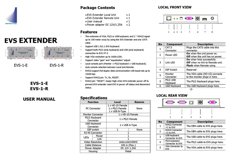
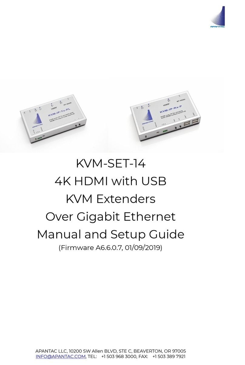
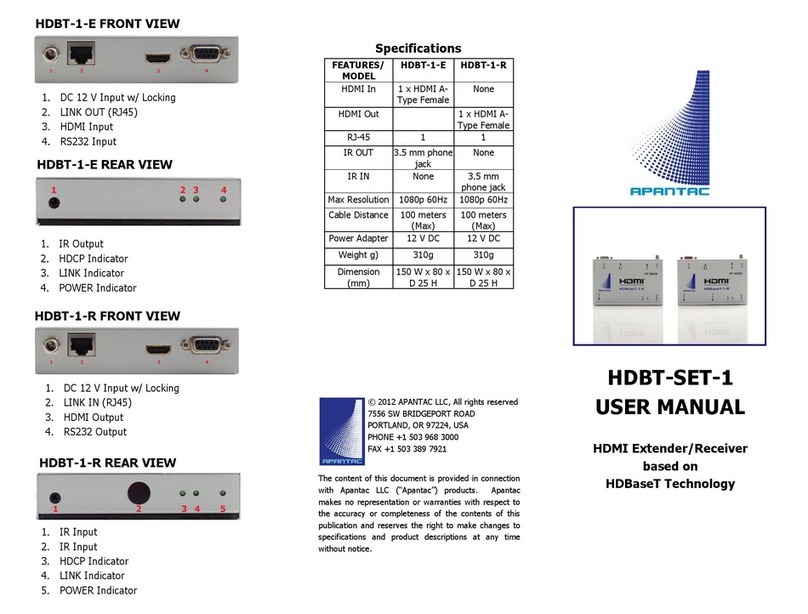
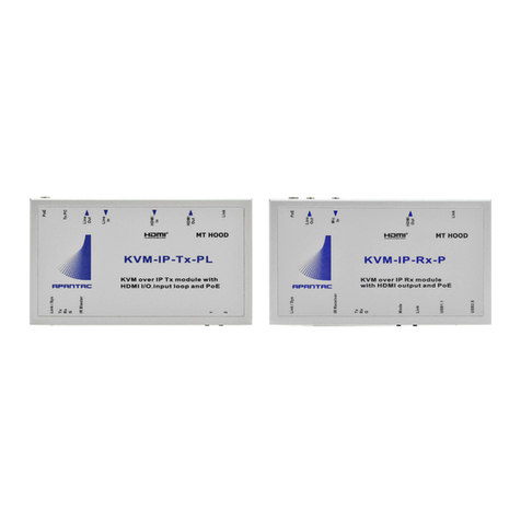
Apantac KVM-IP-Tx User manual

KVM-IP-Tx/Rx
APANTAC LLC, 10200 SW ALLEN BLVD, STE C, BEAVERTON, OR 97005, USA
[email protected], TEL: +1 503 968 3000, FAX: +1 503 389 7921
KVM-IP-Tx/Rx
(KVM-SET-12-II)
User Manual v1.0

KVM-IP-Tx/Rx
APANTAC LLC, 10200 SW ALLEN BLVD, STE C, BEAVERTON, OR 97005
[email protected], TEL: +1 503 968 3000, FAX: +1 503 389 7921
1
COPYRIGHT and TRADEMARK
All rights reserved by APANTAC LLC, Portland, Oregon, USA. No part of this document may be
reproduced in any form or by any means without written permission from the product
manufacturer. Changes are periodically made to the information in this document. They will be
incorporated in subsequent editions. The product manufacturer may make improvements and /or
changes in the product described in this document at any time.
All the registered trademarks referred to this manual are belonging to their respective companies.
WARRANTY STATEMENT
Apantac LLC (herein after referred to as “Apantac”) warrants to the original purchaser of the
products manufactured by Apantac (the “Product,”) will be free from defects in material and
workmanship for a period of three (3) year from the date of shipment of the Product to the
purchaser.
If the Product proves to be defective during the three (3) year warranty period, the purchaser’s
exclusive remedy and Apantac’s sole obligation under this warranty is expressly limited, at
Apantac’s sole option to:
(a) repair the defective Product without charge for parts and labor or,
(b) provide a replacement in exchange for the defective Product or,
(c) if after a reasonable time, is unable to correct the defect or provide a replacement Product
in good working order, then the purchaser shall be entitled to recover damages subject to
the limitation of liability set forth below.
Limitation of Liability
Apantac’s liability under this warranty shall not exceed the purchase price paid for the defective
product. In no event shall Apantac be liable for any incidental, special or consequential damages,
including without limitation, loss of profits for any breach of this warranty.
If Apantac replaces the defective Product with a replacement Product as provided under the
terms of this Warranty, in no event will the term of the warranty on the replacement Product
exceed the number of months remaining on the warranty covering the defective Product.
Equipment manufactured by other suppliers and supplied by Apantac carries the respective
manufacturer’s warranty. Apantac assumes no warranty responsibility either expressed or
implied for equipment manufactured by others and supplied by Apantac.

KVM-IP-Tx/Rx
APANTAC LLC, 10200 SW ALLEN BLVD, STE C, BEAVERTON, OR 97005
[email protected], TEL: +1 503 968 3000, FAX: +1 503 389 7921
2
This hardware warranty shall not apply to any defect, failure or damage:
a) Caused by improper use of the Product or inadequate maintenance and care of the
Product;
b) Resulting from attempts by those other than Apantac representatives to install, repair, or
service the Product;
c) Caused by installation of the Product in a hostile operating environment or connection of
the Product to incompatible equipment;

KVM-IP-Tx/Rx
APANTAC LLC, 10200 SW ALLEN BLVD, STE C, BEAVERTON, OR 97005
[email protected], TEL: +1 503 968 3000, FAX: +1 503 389 7921
3
Table of Contents
1.0 WHAT’S IN THE BOX (When sold in pairs)..................................................................... 4
2.0 Key Features ........................................................................................................................ 4
2.1 Specifications..............................................................................................................5
2.1.1 Default Settings ....................................................................................................... 6
2.1.2 Bandwidth chart ...................................................................................................... 6
2.2 Front/Rear Views ........................................................................................................7
3.0 Installation.................................................................................................................. 9
3.1 Operation..................................................................................................................12
3.1.1 Device Manager Setting.........................................................................................12
3.2 Configuration...........................................................................................................13
3.1.1 System Configuration ............................................................................................14
3.1.2 Network Configuration...........................................................................................14
3.1.3 Function Configuration..........................................................................................16
4.0 Installation................................................................................................................18
4.1 USB and KM over IP Installation ..........................................................................19
4.2 Rx OSD Main Menu.................................................................................................20
4.3 Rx OSD Transmitter List ........................................................................................21

KVM-IP-Tx/Rx
39
1.0 WHAT’S IN THE BOX (When sold in pairs)
Note: KVM-1-EH-LAN and KVM-1-RH-LAN can also be sold separately
QTY
Product
Description
1
KVM-IP-Tx:
KVM Extender (Transmitter)
1
KVM-IP-Rx:
KVM Receiver (Receiver)
2
12 V DC power supply
1
Type A to Type B USB Cable comes
with KVM-1-EH-LAN
2.0 Key Features
–KVM-IP-Tx/Rx are based on Gigbit Ethernet (IGMP and Jumbo frame) technology
–Supports up to 170 meters point to point with CAT6 cables
–Supports up to 100 meters when using with a GigE Switch
–Supports HDMI, DVI or analog VGA (slide switch) input and output signals
–Supports point-to-point (Unicast), one-to-many (Multicast) for Audio/Video
distribution

KVM-IP-Tx/Rx
APANTAC LLC, 10200 SW ALLEN BLVD, STE C, BEAVERTON, OR 97005
[email protected], TEL: +1 503 968 3000, FAX: +1 503 389 7921
5
–Supports KVM extension/switching connected via USB
–Receiver unit has 4 USB ports to easily extend peripherals such as flash drives, keyboard
and mouse
–Supports data transfer (USB attached drives) from Rx to Tx
–Supports USB touch screen extension
–Supports bi-directional stereo audio. (Example, speakers or microphones on the
Rx)
–Supports IR transmission (Rx to Tx). (Example, IR remote control at Rx to control
the DVD player or set-top box connected to Tx)
–Supports RS-232 communication between Tx and Rx
–Built-in webpage for basic configuration (setting of IP address, device name,
Multi/Unicast, Baud Rate and etc)
–Connection Manager Software for Tx/Rx management.
–Supports resolution up to 1920x1080 (HDMI/VGA) / 1920X1200 (DVI).
–EDID Copy function
–Built-ion scaler function
–LED status indicators
–Plug-and-play
2.1 Specifications
Model KVM-IP-Tx KVM-IP-Rx
Transmitter
Receiver
Video Input DVI-I (HDMI/DVI+VGA) N/A
Output N/A DVI-I (HDMI/DVI+VGA)
Audio
Input
3.5mm Stereo Phone Jack
Output 3.5mm Stereo Phone Jack N/A
Microphone
Input
N/A
3.5mm Stereo Phone Jack
USB Upstream USB Type B (Female) N/A
Downstream
N/A
4x USB Type A (Female)
System Link Input N/A RJ-45
Output
RJ-45
N/A
IR / Frequency 3.5mm Stereo Phone Jack / 20~60 KHz
RS-232 / Baud Rate
3-pin Pheonix Terminal Block / up to 115,200 bps / Full
Duplex
Video Resolution (Max.) HDMI/VGA: 1920x1080@60Hz / DVI: 1920X1200@60Hz

KVM-IP-Tx/Rx
APANTAC LLC, 10200 SW ALLEN BLVD, STE C, BEAVERTON, OR 97005
[email protected], TEL: +1 503 968 3000, FAX: +1 503 389 7921
6
Interconnect Cable Standard CAT.6/6a/7 network cable
Maximum Cable Length
170m point to point, 100m when working with switch
Operation Temperature 0 ~ 50°C
Storage Temperature
-20 ~ 85°C
Environment Humidity 0 ~ 80% (Non-condensing)
Power Consumption
400mA
400mA
Power Supply DC 12V, 1.5A DC 12V, 1.5A
Housing / Color
Metal / Silver
Weight 600g 600g
Dimension ( WxDxH )
153.4x88.2x31.5 mm
153.4x88.2x31.5 mm
2.1.1 Default Settings
Both multicast and unicast modes are supported. The default is set to unicast, direct
connection and Jumbo Frame. It is pre-configured as point to point.
Multicast Mode
In multicast mode, the system can be setup to be one to one, one to many, multiple
transmitters to multiple receivers.
The analog audio output of the transmitter and the input of the receiver is turned off in
the multicast mode. Analog audio is only passed from the transmitter to the receiver.
Unicast Mode
Unicast mode is sutable for one to one or multiple transmitters to one receiver.
The bi-directional analog audio transmission only works in unicast mode.
2.1.2 Bandwidth chart
Resolutions @60Hz
Average BW (Mbps)
Resolutions @ 60Hz
Average BW (Mbps)
800x600 50 ~ 60 1440x900 60 ~ 70
1024x768
40 ~ 70
1680x1050
70 ~ 90
480P 50 ~ 60 1280x1024 60 ~ 90
720P
80 ~ 90
1920x1080
70 ~ 110
The above bandwidth chart does not include USB transmission, it consumes up to 50
Mbps when USB mass storage data is transmitted.

KVM-IP-Tx/Rx
APANTAC LLC, 10200 SW ALLEN BLVD, STE C, BEAVERTON, OR 97005
[email protected], TEL: +1 503 968 3000, FAX: +1 503 389 7921
7
2.2 Front/Rear Views
KVM-1-Tx
•Status Indicator LED
oSYSTEM (Green) / LINK (Yellow)
oGreen Blinking / Yellow Off: System is starting up.
oGreen On / Yellow Off: System is ready, but TX/RX not connected.
oGreen On / Yellow Blinking: TX/RX connected but waiting for Video input.
oGreen On / Yellow On: TX/RX connected, Video input is ready.
•RS-232 (DCE)
•IR
•FUNCTION
oPress and Hold and Power ON until Green and Amber LED blinking *
oTo reset to the Factory default setting.
oTo enter Setup and Firmware upgrade mode in IP 192.168.0.88
•MODE Button
oShort press - Set to Video/Graphics mode.
oLong press (3 sec.) - To Enable/Disable Anti-Dither.
Note: For some of ATI graphic card with Dithering function enabled, you
may want to enable Anti-Dither to achieve the better video quality.
•D/A switch - Digital to Analog Signal Switch (HDMI/DVI to VGA)
•LINK OUT
•VIDEO IN

KVM-IP-Tx/Rx
APANTAC LLC, 10200 SW ALLEN BLVD, STE C, BEAVERTON, OR 97005
[email protected], TEL: +1 503 968 3000, FAX: +1 503 389 7921
8
Use DVI-to-DVI, DVI-to-HDMI, DVI-to-VGA cable to input DVI-DI / HDMI /
VGA signals
•LINE IN
•LINE OUT
•USB IN
•Power Jack (DC 12V 1A)
KVM-1-Rx
•Status Indicator LED
oSYSTEM (Green) / LINK (Yellow)
oGreen Blinking / Yellow Off: System is starting up.
oGreen On / Yellow Off: System is ready, but TX/RX not connected.
oGreen On / Yellow Blinking: TX/RX connected, but waiting for Video input.
oGreen On / Yellow On: TX/RX connected, Video input is ready.
•D/A switch - Digital to Analog Signal Switch (HDMI/DVI to VGA)
•IR
•RS-232 (DTE)
•MODE Button
oShort press - Set to Video/Graphics mode.
oLong press (3 sec.) - To Enable/Disable Anti-Dither.
Note: For some of ATI graphic card with Dithering function enabled, you
may enable Anti-Dither to achieve the better video quality.
•Press and Hold and Power ON until Green and Amber LED blinking - Retreive EDID

KVM-IP-Tx/Rx
APANTAC LLC, 10200 SW ALLEN BLVD, STE C, BEAVERTON, OR 97005
[email protected], TEL: +1 503 968 3000, FAX: +1 503 389 7921
9
from Rx’s monitor.
•FUNCTION Button
oTo enter Setup and Firmware upgrade mode in IP 192.168.0.88
oTo get the RX OSD Main Menu
oTo get the USB access right.
•USB Devices
•LINK IN
•VIDEO
Use DVI-to-DVI, DVI-to-HDMI, DVI-to-VGA cable to input DVI-DI / HDMI / VGA
signals
•MIC IN
•LINE OUT
•Power Jack (DC 12V 1A)
3.0 Installation
Fig 1: Point to Point

KVM-IP-Tx/Rx
APANTAC LLC, 10200 SW ALLEN BLVD, STE C, BEAVERTON, OR 97005
[email protected], TEL: +1 503 968 3000, FAX: +1 503 389 7921
10
Fig 2: Multiple point to Point

KVM-IP-Tx/Rx
APANTAC LLC, 10200 SW ALLEN BLVD, STE C, BEAVERTON, OR 97005
[email protected], TEL: +1 503 968 3000, FAX: +1 503 389 7921
11
Fig 3: Multi-point to mult-point

KVM-IP-Tx/Rx
APANTAC LLC, 10200 SW ALLEN BLVD, STE C, BEAVERTON, OR 97005
[email protected], TEL: +1 503 968 3000, FAX: +1 503 389 7921
12
3.1 Operation
3.1.1 Device Manager Setting
1. Connect all TX/RX devices with the PC in the same Gigabit Ethernet switch with
CAT6 cables.
2. Power On all TX/RX devices.
3. Double clickthe on icon to run the "KVM-IP-Config Setting" program and select the
correct Network Card which is connecting with TX/RX devices if more than one NIC
in your PC.
4. The “KVM-IP-Config” will search network for all TX/RX devices and display their
common settings as below: Name, IP, Casting Mode, VW, USB over IP, Serial over
IP, Version, MAC
5. You can double click each TX and RX to display the detail information
and modify the settings as below:

KVM-IP-Tx/Rx
APANTAC LLC, 10200 SW ALLEN BLVD, STE C, BEAVERTON, OR 97005
[email protected], TEL: +1 503 968 3000, FAX: +1 503 389 7921
13
6. You can change TX/RX settings, like Device Name, IP Mode (Auto IP or
Static IP), IP Address (only in Static IP), Subnet Mask (only in Static IP),
Multicast/Unicast, Multicast IP, RX Connection Method, RX Channel Select,
Video-Wall (not currently supported), USB over IP On/Off, Serial over IP
On/off, RS-232 Operation Mode (Type 2/1), Baud Rate.
7. Click “Factory Default” button to reset the device to Factory Default
setting.
8. Click “Chrome” button to open Chrome browser for this unit.
(only for the same subnet with the controller PC)
9. Click “Save” button to save the settings, the device will be re-booted.
The “KVM-IP-Config Setting” will show the updated settings after
re-booted.
3.2 Configuration
The TX/RX Web page control has two modes
•Setup mode
•Operation mode
The TX/RX can be configured in Operation Mode through Ethernet Switch or
direct connection. To enter Operation Mode Web page:
1. Set PC IP 10.0.1.1, Net Mask 255.0.0.0.
2. Open Browser then enter TX/RX IP: 10.xx.xx.xx
3. The TX/RX Operation Mode Web page are shown as the below

KVM-IP-Tx/Rx
APANTAC LLC, 10200 SW ALLEN BLVD, STE C, BEAVERTON, OR 97005
[email protected], TEL: +1 503 968 3000, FAX: +1 503 389 7921
14
The TX contains 3 tab menus [System], [Network], [Functions],
The RX contains 4 tab menus [System], [Video Wall], [Network],
*Note: Video Wall is currently not supported
[Functions]
3.1.1 System Configuration
[Version Information]:
[Upgrade Firmware]:
1. Enter Operation Mode Web page [System] ---> [Update
Firmware] ---> navigate to the
firmware file (.bin) then click [Upload] to start firmware upgrade.
2. The firmware upgrade takes about 3 min., it will display
“DONE Rebooting…” to indicate the unit has been upgraded and
rebooted.
[Utilities]: Factory Default、Reboot、Reset EDID to Default Value、Console
API Command
[Statistics]: State Machine、Network、Video
3.1.2 Network Configuration
The TX/RX provides the following Network related
settings:
【To change IP】
Enter TX/RX Operation Mode Web page [Network]
[IP Setup] select Auto IP, DHCP, Static
enter device IP, Subnet Mask, Default Gateway [Apply].

KVM-IP-Tx/Rx
APANTAC LLC, 10200 SW ALLEN BLVD, STE C, BEAVERTON, OR 97005
[email protected], TEL: +1 503 968 3000, FAX: +1 503 389 7921
15
【To change Casting Mode】(TX)
Enter TX Web page [Network] [Casting Mode]
select [Multicast] or [Unicast] enter the
Multicast IP address with 225.0.x.x [Apply]. (Default Multicast)
Note: Each TX comes with one Individual IP address and one Multicast IP
address that are both shown on the unit label.
【To change Casting Mode】(RX)
There are 4 Connection Methods for
Multicast RX: First Available, Multicast IP, OSD
Transmitter List, and Direct Connection.
There are 3 Connection Methods for
Unicast RX: OSD Transmitter List, TX IP and
Direct Connection.
1. First Available: the RX will connect
to the first available TX.
2. Multicast IP: 225.0.xxx.xxx: the RX will connect to the TX that
is using the same Multicast IP address. (You can setup TX Multicast IP
on the TX [Network] ---> [Casting Mode])
3. OSD Transmitter List: the RX will show up the available
Transmitters for user to select.
4. TX IP: x.x.x.x: the RX will connect to this dedicated TX only.
5. Direct Connection: this setting enables RX to connect TX by
the same subnet, same Casting Mode, Jumbo Frame will be enabled.
【To show TX Device name when connected】(RX only)
This feature enables RX to pop up the TX name (or IP) when
connected. Default is enabled with 5 seconds.
【To Enable/Disable Jumbo Frame】
To enable or disable it, enter TX/RX
Operation Mode
Web page [Network] [Jumbo Frame]
Enable/Disable [Apply] the unit will save the setting and reboot
automatically.
(Default Enable)

KVM-IP-Tx/Rx
APANTAC LLC, 10200 SW ALLEN BLVD, STE C, BEAVERTON, OR 97005
[email protected], TEL: +1 503 968 3000, FAX: +1 503 389 7921
16
3.1.3 Function Configuration
【To change Device Name】
Enter TX/RX Operation Mode Web page
[Functions] [Device Name] enter name (8 characters) [Apply]
to save the device name.
【To Enable/Disable K/M over IP (TX); KMoIP ports (RX)】
The system supports both USB-over-IP and KM-over-IP for USB extension.
The USB-over-IP
works as a virtual 5-port USB HUB when TX is connected to PC, it is
compatible with most of USB devices such as keyboard, mouse, Pen Drive,
Touch Screen… etc.
The KM-over-IP is a HID emulation built for multiple RXs to share
keyboard/mouse for one PC, it takes one port of the 5 virtual ports. The
KM-over-IP setting is different for TX and RX:
For TX: enter TX Operation Mode Web page [Functions] [USB over IP]
[Compatibility Mode] check/uncheck [K/M over IP] to Enable/Disable
[Apply]. (Default Enable)
For RX: enter RX Operation Mode Web page [Functions] [KMoIP ports]
check/uncheck 1, 2, 3 to Enable/Disable KM-over-IP ports
[Apply].
(Default All Disabled)
【To define Hotkey】(RX)
The RX supports Hotkey for OSD Menu.
You can choose the Hotkey: enter RX Operation
Mode Web page [Functions] [Hotkey] select the Hotkey of
<Ctrl><Ctrl>, <Shift> <Shift>, <Alt> <Alt>, or <Scroll> <Scroll> (Default Ctrl
Ctrl).
【To Enable/Disable USB over IP】(TX/RX)
Enter TX Operation Mode Web page
[Functions] [USB over IP]

KVM-IP-Tx/Rx
APANTAC LLC, 10200 SW ALLEN BLVD, STE C, BEAVERTON, OR 97005
[email protected], TEL: +1 503 968 3000, FAX: +1 503 389 7921
17
[Enable USB over IP]
check/uncheck to Enable/Disable
(Default Enable).
•Compatibility Mode: (TX)
oMouse not responding well
Enable this setting if the USB mouse response slow (Default
Disabled)
oK/M over IP
Check this setting to enable TX’s KM over IP (built-in HID)
feature. (Default Disabled)
【To Enable/Disable Serial over IP, and select Operation Mode】(TX/RX)
Enter TX/RX Operation Mode Web page
[Functions] [Serial over IP]
check/uncheck to Enable/Disable (Default
Enable).
Enter TX/RX Operation Mode Web page
[Functions] [Serial over IP]
[Operation Mode] select options of
Type 1, Type 2, Type 1 guest mode, Type 2
guest mode (Default Type 2).
Note:
1. Type 1 is mainly for Unicast application where user can
dynamically link with any target RX.
2. Type 2 is mainly for Multicast application where TX RS-232 will
link with all of connected RXs (Default).
3. Type 1 guest mode is similar to type 1 but using PC to link with
RX’s RS-232.
4. Type 2 guest mode is similar to type 2 but using PC to link with
RX’s RS-232.
【To define RS-232 parameters for Type 2】(TX/RX)
Enter TX/RX Operation Mode Web page [Functions] [Serial over
IP] [Baud rate Setting for Type 2] select Baud rate, Data bits,
Parity, Stop bits. (Default 115200, 8-n-1)

KVM-IP-Tx/Rx
APANTAC LLC, 10200 SW ALLEN BLVD, STE C, BEAVERTON, OR 97005
[email protected], TEL: +1 503 968 3000, FAX: +1 503 389 7921
18
【Audio Output】(RX only)
If the TX’s input audio is HDMI, you can
select the Audio to be output on Line
Out:
Enter RX Operation Mode Web page [Functions] [Audio Output]
check “HDMI Audio De-Embedder” for the audio output to Line-Out.
Click [Apply] to save the setting and reboot.
【Multi-Screen Setting】(TX/RX)
The system supports Multi-Screen
feature for PC with multiple screens.
Each TX/RX can define its associated
2nd, 3rd, 4th TX/RX IP. So, when the
Main RX switches to a new TX, its associated RXs will also be
switched to that new TX’s associated TXs automatically.
Enter TX/RX Operation Mode Web page [Functions]
[Multi-Screen Setting] then enter IP address for the associated 2nd,
3rd, 4th TX/RX IP.
․Mirror: (RX)
There is an option of “Mirror”, when enabled, the associated RXs will
connect to the same TX as the Main RX is connecting. This enables
multiple RXs to display the same TX as a splitter.
4.0 Installation
1. By factory default, the KVM-IP-Tx/Rx is pre-configured with Unicast,
Direct Connection and Jumbo Frame. It is configured for one-to-one
as pairing connection. The maximum distance between TX and RX is
170 meters by using CAT6/6a or CAT7 cable.
2. Connects RX DVI-I to HDMI/DVI/VGA screen by a
DVI-to-HDMI/DVI-to-DVI/DVI-to-VGA cable.
3. The RX will get EDID from screen and send to TX during connection
with TX.
4. The RX will display the following start-up messages when powered
on:
FW: 15-Nov-18 A5.3.4 ---> Firmware version
Local IP: 10.0.29.72 ---> RX’s IP address

KVM-IP-Tx/Rx
APANTAC LLC, 10200 SW ALLEN BLVD, STE C, BEAVERTON, OR 97005
[email protected], TEL: +1 503 968 3000, FAX: +1 503 389 7921
19
Remote IP: 10.0.29.73 ---> Connecting TX IP address
ID: 0020FE001122 ---> RX’s MAC address
Connection Method ---> Direct Connection
5. Attach HDMI/DVI source (PC or Blue-Ray) to the TX’s DVI-In then power
ON the TX unit. The TX’s Green LED will blink then ON indicating ready
and waiting for connection with RX.
6. As long as TX/RX connection established, both of TX and RX Amber
LED will start to blink indicating wait for video input source (Green LED
is ON).
7. If you are using PC as video source, it is recommended to check if the
correct screen EDID shown on PC graphic card control panel.
8. Activate video source with audio to TX, then check if RX correctly
display. In this step, both Green and Amber LED should be ON
indicating the unit is ready and video source is also ready.
4.1 USB and KM over IP Installation
1. Connect TX USB-B to PC, OS will detect a Generic USB Virtual Hub
Device.
2. The system can support both “USB-over-IP” and “KM-over-IP”.
3. The USB-over-IP works as a Virtual 5-port HUB when connected to TX, it
is compatible with most kind of USB devices such as keyboard, mouse,
Pen Drive, Touch Screen… The USB-over-IP connection can be
configured in “Active on link” (Sharing) mode or in “Active per request”
(Exclusive) mode (Default). In “Active on link” mode, the maximum
USB-over-IP connection for a TX is 5 due to the 5 ports of Virtual HUB.
4. The KM-over-IP means that port will work as HID device only for
keyboard/mouse emulation, the PC don’t get BIOS “Keyboard Error” if
there is no real keyboard attached during boot up. It is not necessary to
gain USB access right for the KM-over-IP port. The TX (PC) can be
shared with multiple RXs for keyboard/mouse access in KM-over-IP
mode.
5. There are 3 USB-A ports on the RX. The factory default setting for the
TX is both of USB-over-IP and KM-over-IP enabled, all 3 USB ports of RX
are in USB-over-IP mode (KM-over-IP Disabled).
6. There are 2 methods to gain the access right for a USB-over-IP port:
a. Long press (3 sec.) the RX [FUNCTION button]
b. Press “U” key to toggle during Transmitter List OSD menu.
The RX display “Requesting USB” to indicate starting USB-over-IP
This manual suits for next models
2
Table of contents
Other Apantac Extender manuals