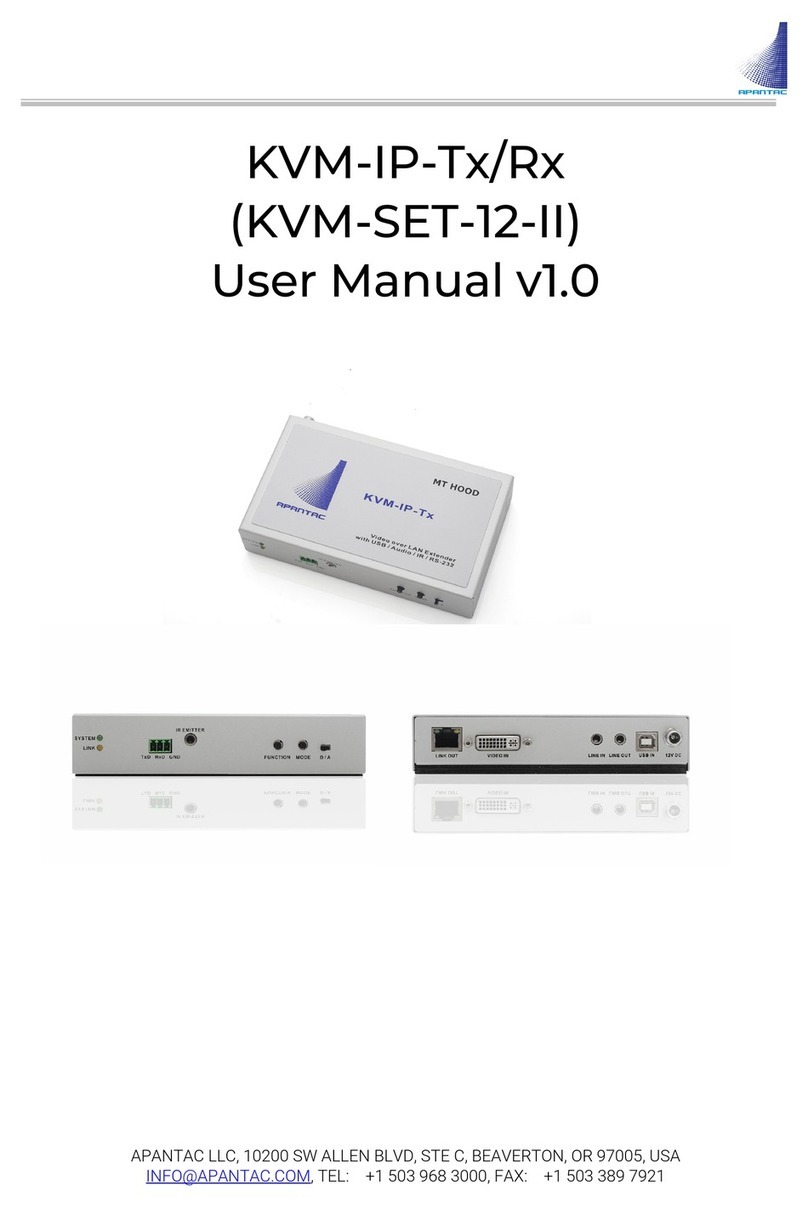
Apantac KVM User guide

APANTAC LLC, 10200 SW Allen Blvd. Suite C, Beaverton, OR 97005 USA
info@apantac.com – Telephone: +1 503 968 3000 - Fax: +1 503 389 7921 – www.apantac.com
1
KVM over IP Matrix
Start-up Guide
This document provides step by step instructions on how to install and configure a KVM
over IP matrix using Apantac Tx and Rx modules. For a detailed description of some
features or specific configuration menus such as Video Wall, please refer to the specific
product manuals.

APANTAC LLC, 10200 SW Allen Blvd. Suite C, Beaverton, OR 97005 USA
info@apantac.com – Telephone: +1 503 968 3000 - Fax: +1 503 389 7921 – www.apantac.com
2
TABLE OF CONTENTS
Overview................................................................................................................................................. 3
Installation.............................................................................................................................................. 5
Configuration ........................................................................................................................................ 7
Tx Configuration – first pass............................................................................................................... 8
Rx Configuration – first pass............................................................................................................... 9
Tx Configuration – second pass ....................................................................................................... 10
Rx Configuration – second pass....................................................................................................... 14
System Final Tests............................................................................................................................. 17
Contact Apantac Technical Support........................................................................................... 18

APANTAC LLC, 10200 SW Allen Blvd. Suite C, Beaverton, OR 97005 USA
info@apantac.com – Telephone: +1 503 968 3000 - Fax: +1 503 389 7921 – www.apantac.com
3
Overview
Apantac offers various Tx and Rx models that can all reside on the same network and
work together, which include:
•The KVM-IP-Tx & KVM-IP-Rx have DVI-I input and output connectors and support
resolutions up to 1920 x 1200 @ 60Hz. They ship with their own wall mount power
supply.
•The KVM-IP-Tx-F & KVM-IP-Rx-F are identical to the KVM-IP-Tx & KVM-IP-Rx but
with a SFP fiber slot in place of the RJ45 connector for IP connection.
•The KVM-IP-Tx2 & KVM-IP-Rx2 are the dual head version of the KVM-IP-Tx & KVM-
IP-Rx. E.g. a KVM-IP-Tx-2 is equivalent to two KVM-IP-Tx in a single enclosure and
with a unique external power supply.

APANTAC LLC, 10200 SW Allen Blvd. Suite C, Beaverton, OR 97005 USA
info@apantac.com – Telephone: +1 503 968 3000 - Fax: +1 503 389 7921 – www.apantac.com
4
•The KVM-IP-Tx-PL & KVM-IP-Rx-P have an HDMI input and output, with an input
loop for the KVM-IP-Tx-PL, POE and support resolutions up to 4K @ 30Hz. They
ship without any power supply. An optional KVM-IP-Tx-PL-PS wall mount power
supply is available in case the IP Switch does not have POE capability. It can be
used with the Tx or the Rx.
•The OG-KVM-IP-Tx is the card version of the KVM-IP-Tx-PL box. Up to ten OG-
KVM-IP-Tx cards can be installed in one 2RU openGear chassis that will provide
single or redundant power supplies, and the Dashboard interface for monitoring
the cards status.

APANTAC LLC, 10200 SW Allen Blvd. Suite C, Beaverton, OR 97005 USA
info@apantac.com – Telephone: +1 503 968 3000 - Fax: +1 503 389 7921 – www.apantac.com
5
Installation
The Tx an Rx need to be connected to a managed GigE IP Switch that supports IGMP
snooping and 9K jumbo frames. Tx and Rx modules are preconfigured for Jumbo frames
support (this can be disabled in the configuration) and will not work if the IP Switch is not
supporting or enabled for Jumbo frames first.
If KVM-IP-Tx-PL or KVM-IP-Rx-P modules are used, a POE switch is preferred.
We recommend configuring the IP Switch for IGMP, IGMP Snooping and Jumbo frames
first. For example, here is how this is done with a D-Link switch:
•Launch your web browser, enter the Switch management IP address, and connect
to the configuration console (password protected).
•Enable Jumbo Frames.
•Enable IGMP Snooping
Install now the Tx and Rx modules (or
cards). All the modules have a magnetic
base and come as standard with a metal
plate for an easy installation. For example,
you can screw Rx mounting plates inside a
wooden console or under a table and “stick”
the module on the mounting plate. For Tx
you can remove the mounting plate and
“stick” the module directly onto a metallic surface such as the top of a server.

APANTAC LLC, 10200 SW Allen Blvd. Suite C, Beaverton, OR 97005 USA
info@apantac.com – Telephone: +1 503 968 3000 - Fax: +1 503 389 7921 – www.apantac.com
6
The Tx modules with a DVI-I input can accept DVI-D signals, HDMI signals (via
a HDMI > DVI-D adapter or cable) or VGA signals (via a VGA > DVI-A adapter
or cable). Make sure the D/A switch is set to “D” when using DVI or HDMI
sources or set to “A” with VGA sources.
Tx modules: Connect the computer video output signal to the Tx video input, one
computer USB port to the “USB IN” Tx port using a USB-B <> USB-A cable and the Tx
“LINK IN” port to the IP Switch using a CAT 5e/6 cable – maximum length is 100 meters.
(Cables and adapters are not included as standard). Except for POE models, or if a POE
switch is not used, connect the power supply and lock the DC input jack to secure the
power connection.
With the KVM-IP-Tx-PL module or the OG-KVM-IP-Tx card you can use the HDMI loop out
(HDMI Out) to connect to a local console monitor, for example.
Tx modules / cards with IP Fiber connectivity will require installing a SPF (may or may not
be included depending on how it was ordered) and connect to the IP Switch over Fiber.
Connect the optional signals (Analog audio, RS-232, InfraRed) in case they are being
used.
Rx modules: Connect Rx video ouput to the console monitor, the keyboard and mouse to
the two “USB 1.1” ports, and the Rx “LINK OUT” port to the IP Switch using a CAT 5e/6
cable – maximum length is 100 meters. (Cables and adapters are not included as
standard). Except for POE models, or if a POE switch is not used, connect the power
supply and lock the DC input jack to secure the power connection.
Rx modules / cards with IP Fiber connectivity will require installing a SPF (may or may not
be included depending on how it was ordered) and connect to the IP Switch over Fiber.
Connect the optional signals (Analog audio, RS-232, InfraRed) in case they are being
used.
Start: You are now ready to apply power to the modules / cards. The front Tx and Rx
LEDs activity is a simple way to figure out the modules status: At boot up the green LED
does short blinks. When the boot up is complete, the LED is permanently lit. If the module
is connected to the network the yellow LED blinks. When a Tx with a valid video input
signal is being switched to one or more Rx consoles, the yellow LED is permanently lit on
the corresponding modules.
(Check the manual for an exhaustive descrition of the LEDs activity).

APANTAC LLC, 10200 SW Allen Blvd. Suite C, Beaverton, OR 97005 USA
info@apantac.com – Telephone: +1 503 968 3000 - Fax: +1 503 389 7921 – www.apantac.com
7
Configuration
When shipped, Tx and Rx are configured with Static IP addresses, with all the modules
usually set for the same subnet (10.0.90.xxx subnet, typically). The screen captures of
this document are based on the A.7.3.1.3 version of the FW.
•First, copy the “AV-95x0 Setting Ver 5.2” Windows configuration application to the
configuration PC and install it.
•Connect the configuration PC to the IP Switch
•Set its IP parameters for the same subnet as the one you plan to use for the Tx
and Rx.
•Launch the application (choose the proper network adapter when asked). Allow it a
bit of time for discovery and ensure the application discovers all of them - even if
your PC IP is not set for the same subnet as the Tx and Rx for now.
At this point you shall see all the Tx and Rx modules that are attached to the network.
You may want to disconnect all the Tx and Rx and only connect one at a time to identify
and configure them. Note that it takes a bit of time to discover again a Tx or Rx once it
has been connected.
For a quicker update, you may want to shut down the application and launch it again.

APANTAC LLC, 10200 SW Allen Blvd. Suite C, Beaverton, OR 97005 USA
info@apantac.com – Telephone: +1 503 968 3000 - Fax: +1 503 389 7921 – www.apantac.com
8
Tx Configuration – first pass
Double click on the row of the Tx you
want to configure. The following menu
will pop up. Here are the
recommended settings:
•Device name: Enter the Tx
name. (10 characters max
without spaces).
•IP Mode: Leave it on Static.
•IP Address, Subnet Mask,
Gateway: Enter the IP
parameters you want to assign
to this Tx.
•Casting mode: Leave it on
Multicast.
•Multicast IP address: Leave it as is. (Each Tx Multicast address should be unique
when shipped).
•Set “Video Wall” and “Serial over IP” to “N,” USB over IP to “Y” and ignore the Serial
Communication Parameters.
•Press “Save”. The Tx will reboot. This Tx row will disappear from the GUI and pop
up again with the new settings.
•Repeat until all Tx are configured.

APANTAC LLC, 10200 SW Allen Blvd. Suite C, Beaverton, OR 97005 USA
info@apantac.com – Telephone: +1 503 968 3000 - Fax: +1 503 389 7921 – www.apantac.com
9
Rx Configuration – first pass
Double click on the row of the Rx you
want to configure. The following menu
will pop up. Here are the recommended
settings:
•Device name: Enter the Rx name.
(10 characters max without
spaces).
•IP Mode: Leave it on Static.
•IP Address, Subnet Mask,
Gateway: Enter the IP
parameters you want to assign
to this Rx.
•Casting mode: Leave it on
Multicast.
•Multicast IP address: Leave it as is. (Each Tx Multicast address should be unique
when shipped).
•Connection Method. Leave it as is.
•Set “Video Wall” and “Serial over IP” to “N”, USB over IP to “Y” and ignore the Serial
Communication Parameters.
•Press “Save.” The Rx will reboot. This Rx row will disappear from the GUI and pop
up again with the new settings.
•Repeat until all Rx are configured.
The application GUI shall now display all the TX and Rx in your configuration with all the
settings you have already completed and the name you have assigned to each.
Quickly check that all settings are OK and that all Tx and Rx are running the same FW
version (ignore extra characters after Ax.x.x.x, if any). You may have to resize the
columns to see all the information. You can also sort the modules based on different
criteria by clicking on the corresponding column name.

APANTAC LLC, 10200 SW Allen Blvd. Suite C, Beaverton, OR 97005 USA
info@apantac.com – Telephone: +1 503 968 3000 - Fax: +1 503 389 7921 – www.apantac.com
10
You are now ready to start the “configuration second pass.” Each Tx and Rx has a web
configuration page that can be accessed using a web browser (Chrome recommended).
You can either directly enter the module IP address in the browser or you can click on the
corresponding row in the application and press the “Chrome” button.
Only the parameters you should check/change in a typical configuration will be
documented here. Some menus may be slightly different depending on the FW version,
but the important functions are identical. Ignore the other ones for now or refer to the
product documentation for more details.
Tx Configuration – second pass
Here is what you get when you connect to a Tx. There are three tabs, each one with its
own settings.

APANTAC LLC, 10200 SW Allen Blvd. Suite C, Beaverton, OR 97005 USA
info@apantac.com – Telephone: +1 503 968 3000 - Fax: +1 503 389 7921 – www.apantac.com
11
System > Utilities TAB:
Commands - “Factory Default”: Do not press unless on purpose. The action is immediate,
and if you did press the button, you will have to reconfigure the Tx from scratch!
Commands – “Reboot”: Settings are organized in sections with an “Apply” button for each.
When you make changes, press the “Apply” button of the corresponding section and once
you have carried out all the changes in all tabs / sections, press the “Reboot” button for
the changes to apply. This will reboot the Tx and the web page will connect again when
the reboot process is complete. This takes a few tens of seconds.
EDID: This setting determines
which EDID table will be exposed
to the computer graphic card,
hence its output resolution. There
are two possibilities. Either one
Rx module is designated as the
“EDID Master” (set in the Rx
menus) and in this case, the EDID
of the monitor attached to this Rx
Master will be exposed to the
computer graphic card. Or (this is
the preferred method,) you shall
pick one resolution in the drop-
down list of predefined EDIDs.
NOTES:
•When / if possible, use the same EDID for all computers. Identical source
resolution will guarantee the shortest switching time between different sources.
•If you have a mix of Rx supporting HD and 4K resolutions, they can all be part of
the same matrix. However, if a 4K Tx streams a 4K video to a HD Rx, the HD Rx will
not be able to decode it and you will get a black screen. This is confusing for
operators. It is possible to configure the Rx to specify which Tx are available to a
console. You may want to use this capability to limit the access that will be
“visible” to a console to the proper Tx.

APANTAC LLC, 10200 SW Allen Blvd. Suite C, Beaverton, OR 97005 USA
info@apantac.com – Telephone: +1 503 968 3000 - Fax: +1 503 389 7921 – www.apantac.com
12
•Another trick is with HDCP content protection. The Tx/Rx connection is
transparent to HDCP. MACs or some recent Window computers protect their
output with HDCP. If you switch them to a console equipped with a monitor not
supporting HDCP, it will stay black. This can be very confusing since the same
computer will be displayed well on another console equipped with a HDCP
compliant monitor, but this console will also display well video sources without
HDCP protection.
Network TAB:
In the network tab you will find the IP settings as they were set during the first pass. No
changes required.
Jumbo frame: Enabled by default. If your IP Switch does
not support Jumbo Frames, them tick “Disabled” and
press “Apply.” This will have to be done for all Tx and Rx.
Functions TAB:
Device name: You can also change the Tx name from this tab.
Video over IP: Video mode / graphic mode choice allows you to optimize compression
parameters depending on the computer use. The differences are almost unnoticeable in
normal conditions (with proper bandwidth between the Tx and the Switch).
There are two ways to control the bandwidth usage from the source when limited
bandwidth between a Tx and the IP Switch is available.
1. The “Maximum Bit Rate” setting allows you to set a limit to the bandwidth the Tx
will use. The default setting is “Best Effort” (adaptive).
2. The “Maximum Frame Rate” setting allows you to control how many frames per
second will be sent by the Tx – E.g. sending only 10 frames per second will give a
better visual result than sending 30 or 60 frame per seconds for a few seconds
and then have a frozen picture for several seconds because of network
congestion.

APANTAC LLC, 10200 SW Allen Blvd. Suite C, Beaverton, OR 97005 USA
info@apantac.com – Telephone: +1 503 968 3000 - Fax: +1 503 389 7921 – www.apantac.com
13
USB over IP: Leave the
“Operation and Compatibility
Mode” settings to default for
best results. Different settings
are used in specific situations.
Note: USB refers to USB 2.0 (E.g.
when extending a touch screen,
tablet, USB memory stick). When
the “Enable USB over IP”
checkbox is not ticked, mouse and keyboard still operate. USB should be disabled. For
example, when you want to prevent copying a USB memory stick content to this server
from any console.
Multi-Screen Setting. The Apantac KVM over IP
solution allows you to switch single, dual, and up to
four head computers in one shot. One Tx per head is
needed.
“Main Video” checkbox shall be ticked in case of a
single head or the “head one” Tx. Head one Tx is
attached to the computer head one video output as
well as the USB. Heads two, three or four Tx are only
sending video. When “Main Video” is checked, the Tx
name will become visible as the computer name in
the console drop-down menu.
The second, third and fourth video Tx IP respectively
are the head two, three and four Tx IP addresses. A
dual head Tx configuration is shown here.

APANTAC LLC, 10200 SW Allen Blvd. Suite C, Beaverton, OR 97005 USA
info@apantac.com – Telephone: +1 503 968 3000 - Fax: +1 503 389 7921 – www.apantac.com
14
Rx Configuration – second pass
Here is what you get when you connect to a Rx. There are three tabs, each one with its
own settings.
System > Utilities TAB:
Commands – “Reboot”: Settings are organized in sections with an “Apply” button for each.
When you perform changes, press the “Apply” button of the corresponding section and,
once you have carried out all the changes you want to do in all the tabs/sections, press
the “Reboot” button for the changes to apply. This will reboot the Rx and the web page
will connect again when the reboot process is complete. This takes a few tens of
seconds.
There is no other setting to care of in this tab.

APANTAC LLC, 10200 SW Allen Blvd. Suite C, Beaverton, OR 97005 USA
info@apantac.com – Telephone: +1 503 968 3000 - Fax: +1 503 389 7921 – www.apantac.com
15
Network TAB:
IP Setup: You will find there the IP settings, as they were set during the first pass.
Casting Mode: Leave it to “First
Available” by defaut.
If you want to limit the list of Tx this
console has access to, tick “OSD
Transmitter List,” “Transmitter IP Range”
and enter the IP addresses of the
“visible” Tx.
Jumbo frame: Enabled by default. If your IP Switch
does not support Jumbo Frames, them tick “Disabled”
and press “Apply.” This will need to be done for all Tx
and Rx.
Functions TAB:
Device Name: You can also change the Rx name from his
tab.
KM over IP Ports: By default, the keyboard and the mouse
should be attached to the two Rx “USB 1.1” ports and ports 1
and 2 checkboxes should be ticked.
Hotkey: This is the console keyboard shortcut that will be
used to access the Tx selection menu. The default is “Ctrl +
Ctrl”.
You can disable the shortcut operation if this console is e.g. used in a public area and you
want to keep full control of the Tx it connects to / assign it externally. You could for
example use the “Connection Manager” for this purpose.

APANTAC LLC, 10200 SW Allen Blvd. Suite C, Beaverton, OR 97005 USA
info@apantac.com – Telephone: +1 503 968 3000 - Fax: +1 503 389 7921 – www.apantac.com
16
Video over IP:
Tick the “Copy EDID from this Video Output” if you want the EDID of the monitor attached
to this Rx to become the “EDID master.” (Refer to the “EDID Master” description in the Tx
“System > Utilities” menu).
Scaler Output Mode: The Rx has a built-it scaler, enabled by default. When being used, the
Rx output resolution will not change, whatever the source computer resolution. The Rx
will up-scale or down-scale the input signal to the output resolution. Thus, the console
monitor will always “get” the same resolution when switching from computer to
computer, resulting in reduced switch time and minimal visual artifacts. By default, the
“Scaler Output Mode” is set for “Auto EDID.” The Rx output resolution will be set according
to the monitor preferred resolution. You can alternatively select a fixed output resolution
in the list or bypass the scaler (“Pass Through”) in the drop-down menu.
Remark: The Rx built-it scaler is also used to crop and zoom one part of the output
picture when the Rx is set for “Video Wall.”
USB over IP: USB in refers to USB 2.0 (e.g. when extending a touch screen, tablet, USB
memory stick). When the “Enable USB over IP” checkbox is not ticked, mouse and
keyboard still operate but USB 2.0 devices are disabled. The main purpose of the Rx
setting is to forbid the use of USB memory sticks from this console.
Multi-Screen Setting. The Apantac KVM over IP solution allows you to switch single, dual
head, and up to four head computers in one shot. One Rx per console head is needed.
Head one Rx is wired to the console head one monitor and has the keyboard and mouse
attached to it. Heads two, three or four Rx are wired to the corresponding monitors,
exclusively.
When an operator connects a multi-head computer to a multi-head console, it connects
the head one Tx to the head one Rx only. Based on the configuration, the “Slave Tx” will
connect to the corresponding “Slave Rx” automatically.
Remarks:
•When e.g. a dual head computer connects to a single head console, only the first
head will be connected.
•When e.g. a single head computer connects to a single dual head console, only the
first head will be connected, and the second head monitor will display a “blue
screen.”

APANTAC LLC, 10200 SW Allen Blvd. Suite C, Beaverton, OR 97005 USA
info@apantac.com – Telephone: +1 503 968 3000 - Fax: +1 503 389 7921 – www.apantac.com
17
To configure a multi-head console, specify the
IP address of the other heads Rx IP
address(es) in the head one Rx menu. No
configuration is needed for the other Rx.
Mirror: A Rx can be configured to follow a
console Rx = Connect to the same source
computer when the user switches it to his console. This is useful when, for example, a big
monitor or a video projector output must been seen by several people and should follow a
user console selection. To configure this, enter the “Mirror Rx” IP address in the console
Rx Multi-Screen setting configuration menu and tick the “Mirror” checkbox.
System Final Tests
Make sure that all the sources and monitors are turned on.
If a console Rx is not connected to any Tx, the monitor will display a status screen
(800x600 resolution) including the Rx IP address, the expected Tx IP address at the
bottom left, and a message at the bottom right: “Trying to find the transmitter.”
Use the console keyboard hotkey (e.g. Ctrl + Ctrl) to pop-up the menu allowing you to
select a valid Tx. There is a star in front of the current selection and a “>” in front of the
next selection. Use the keyboard arrows and, if needed, the PgUp/PgDn buttons to locate
the Tx you want to select. Press enter to do the switch. Some status messages will be
displayed, but you can control the new Tx as soon as you see the new video.
The popup menu information and style can be cycled by pressing the F8 key.
Do not hesitate to contact your Apantac representative or Apantac contact if you need
help with the KVM over IP Matrix configuration.

APANTAC LLC, 10200 SW Allen Blvd. Suite C, Beaverton, OR 97005 USA
info@apantac.com – Telephone: +1 503 968 3000 - Fax: +1 503 389 7921 – www.apantac.com
18
Contact Apantac Technical Support
For technical inquiries including product and system issues, hardware and software
information and more.
Technical Support Hours:
Monday - Friday
7:00 AM to 5:00 PM (PT)
Technical Support Assistance:
Phone: +1 (503) 968-3000
Email: support@Apantac.com
Randall Durand
Technical Support Manager / Applications Engineer
Phone: +1 503 455 4663
Email: Randall.Durand@Apantac.com
Daryn Edwards
Technical Support Engineer
Phone: +1 (503) 968-3000
Email: Daryn.Edwards@Apantac.com
This manual suits for next models
8
Table of contents
Other Apantac Extender manuals