7Zero Adjust (4-20 mA, 0-5 VDC, and 0-10 VDC series Only)
The zero output (4mA or 0 VDC) can be adjusted by holding a magnet perpendicular to the can,
approximately 1-1/2” from the top or bottom of the can.
Holding the magnet close to the top of the can increases the output. Holding the magnet close to
the bottom of the can decreases the output.
If the zero output values do not change right away, hold the magnet in place near the top of the can
until the values change, for up to two minutes. If there is no change, repeat the procedure near the
bottom of the can. If there is still no change, consult the factory.
Unvented PT-500 transmitters do not automatically adjust to changes in barometric pressure. We
recommend that PT-500 transmitters be zeroed upon receipt, and after major weather events.
NOTE: Span calibration must be done at the factory for all analog models.
8Vent Tube Drying
Condensation in the vent tube can damage the electronics in your sensor, resulting in unreliable
readings. APG oers two methods of preventing vent tube condensation: a venting cap and a
desiccant drying cartridge.
The venting cap is a PVC tube with a hydrophobic patch that allows moisture to pass out of the
tube without allowing water in. The cap is sealed by an o-ring, and is easily installed in the eld.
The desiccant drying cartridge with vent tube adapter absorbs any moisture in the vent tube to
keep vapor from condensing. The installation of the desiccant drying cartridge is quick and easy.
Common installation methods are cable tie, Velcro, and cable clamps.
9General Care
Your pressure transmitter is very low maintenance and will need little care, as long as it was
installed correctly. However, in general, you should:
• For process connected sensors, keep the sensor and the area around it generally clean.
• Avoid applications for which the sensor was not designed, such as extreme temperatures,
contact with incompatible corrosive chemicals, or other damaging environments.
• Inspect the threads whenever you remove the sensor from duty or change its location.
• Avoid touching the diaphragm. Contact with the diaphragm, especially with a tool, could
permanently shift the output and ruin accuracy.
• Cleaning the diaphragm or the diaphragm bore should be done with extreme care. If using a
tool is required, make sure it does not touch the diaphragm.
10 Repair Information
If your pressure transmitter needs repair, contact us via email, phone, or on-line chat on our
website. We will issue you an RMA number with instructions.
• Phone: 888-525-7300
• Online chat at www.apgsensors.com
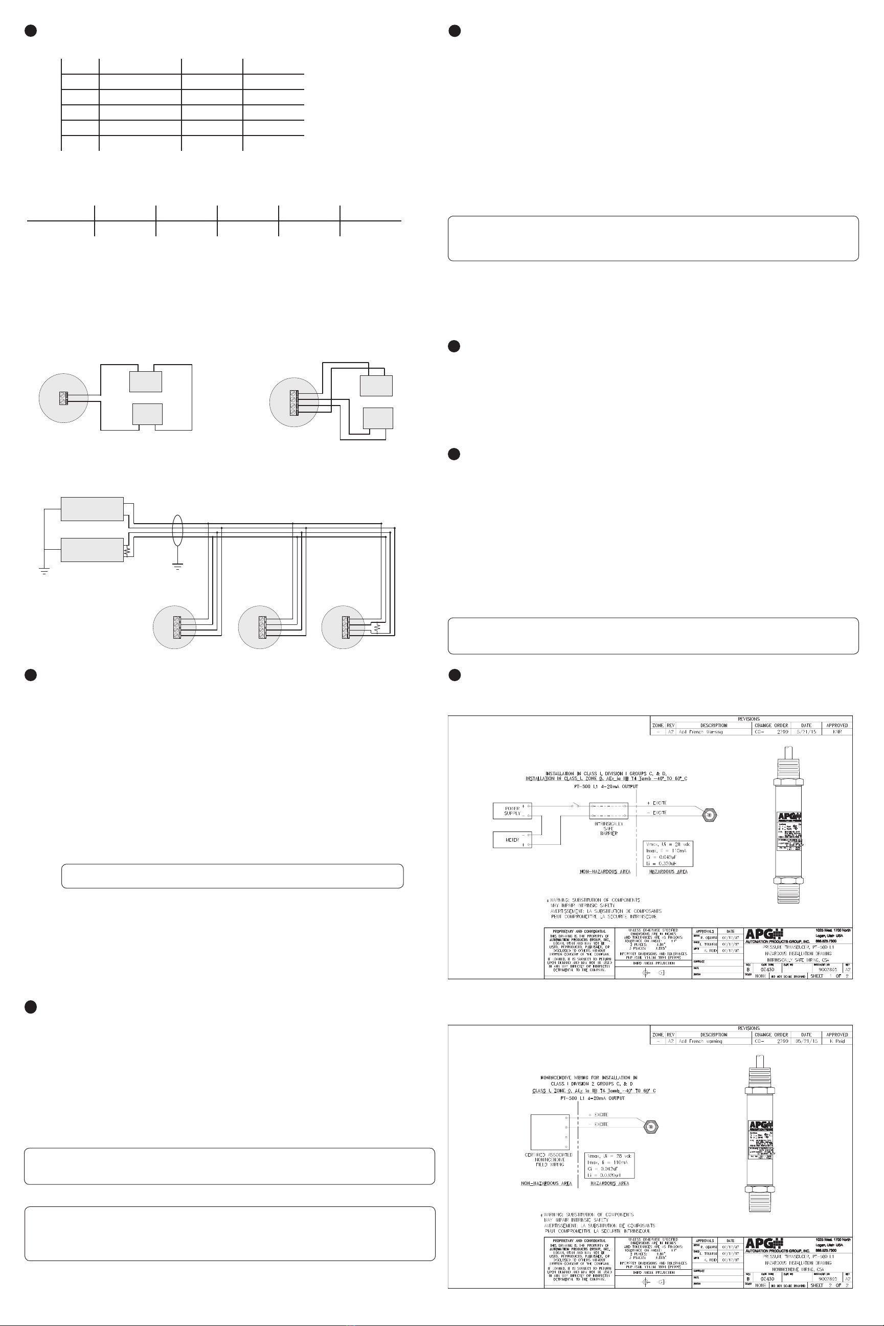
12 Hazardous Location Wiring
11 Removal Instructions
Removing your PT-500 from service must be done with care. It’s easy to create an unsafe situation,
or damage your sensor, if you are not careful to follow these guidelines:
• For sensors installed via NPT process connection, make sure the pressure is completely
removed from the line or vessel. Follow any and all procedures for safely isolating any media
contained inside the line or vessel.
• Remove the sensor with an appropriately sized wrench (per your process connection).
• For suspended sensors, retrieve the sensor from the vessel. Follow any and all procedures for
safely isolating any media contained inside the line or vessel.
• Carefully clean the sensor’s tting and diaphragm of any debris (see General Care) and
inspect for damage.
• Store your sensor in a dry place, at a temperature between -40° F and 180° F.
Intrinsically Safe Wiring (4-20mA Output)
Non-Incendive Wiring (4-20mA Output)
DANGER: Removing the pressure transmitter while there is still pressure in the line or
vessel could result in injury or death.
NOTE: Desiccant crystals change from blue to pink as they become saturated. Cartridge
must be replaced when all crystals have saturated.
IMPORTANT: Do NOT use desiccant cartridge in the presence of vapors of liquids
containing phosphate esters, synthetic lubricant, hydrocarbon solvents, methanol, acetone,
lacquer solvents, or other organics.
IMPORTANT: Any contact with the diaphragm can permanently damage the sensor. Use
extreme caution.
6Wiring Information
PT-500 Series Pin Out Table
Pigtail
4-20 mA Voltage Modbus
Red + Power/Signal + Power + Power
Black - Power/Signal - Power - Power
Green - + Out B (TX-)
White - - Out A (TX+)
Shield Case Gnd Case Gnd Case Gnd
PT-500 Series Supply Power Table
4-20 mA 0-5 VDC 0-10 VDC mV/V Modbus
Power Supply 9-28 VDC 9-28 VDC 14-28 VDC 10 VDC* 5-28 VDC
* mV/V output calibrated to 10 VDC input.
PT-500 Modbus System Wiring
Power
Supply
+5-28 Vdc
GND Use Shielded Cable
120 Ω
terminating
resistor
120 Ω terminating
V+
B (TX-)
A (TX+)
Sensor 1
GND
V+
B (TX-)
A (TX+)
Sensor 2
GND
V+
B (TX-)
A (TX+)
Sensor 3
GND
Master
Device
RS-485 A (TX+)
RS-485 B (TX-)
PT-500 modbus
series sensor
PT-500 modbus
series sensor
PT-500 modbus
series sensor
Note: PT-500 modbus sensors use
reversed TX+/TX- pins. When connecting
to your system, ensure continuity
of TX- to TX- and TX+ to TX+, rather than
A to A and B to B.
Sensor
9-28 Vdc
Out
Input Com
Receiver
+
Power Source
(9-28 Vdc)
−
Red
Black
PT-500 4-20 mA System Wiring
Sensor
V+ V-
Receiver
+
Power Source
(VDC per model)
−
Red Black
Out -
VDC -
VDC +
Out +
White Green
PT-500 Voltage System Wiring


