manuals.online logo
Brands
  1. Home
  2. •
  3. Brands
  4. •
  5. APG
  6. •
  7. Transmitter
  8. •
  9. APG PT-405 Series User manual

APG PT-405 Series User manual

PT-405 Series Pressure Transmitters
Installation Guide
Heavy Duty, Explosion Proof
R
APG
Automation Products Group, Inc.
1025 W 1700 N Logan, UT 84321
www.apgsensors.com | phone: 888-525-7300 | email: [email protected]
Thank You
Thanks for purchasing a Series PT-405 pressure transmitter from us! We appreciate your business
and your trust. Please take a moment to familiarize yourself with the product and this manual
before installation. If you have any questions, at any time, don’t hesitate to call us at 888-525-7300.
This product is covered by APG’s warranty to be free from defects in material and workmanship
under normal use and service of the product for 24 months. For a full explanation of our Warranty,
please visit https://www.apgsensors.com/about-us/terms-conditions. Contact Technical Support to
receive a Return Material Authorization before shipping your product back.
Scan the QR code below to read the full explanation of our Warranty on your tablet or smartphone.
1.Description
2. How To Read Your Label
3. Warranty
4. Dimensions
5. Mounting Instructions
6. Wiring Information
7. Zero Trimming
8. Re-calibration
9. General Care
10. Repair Information
11. Removal Instructions
6Wiring Information
Table of Contents
5Mounting Instructions
The PT-405 should be installed in an area--indoors or outdoors--which meets the following
conditions:
• Ambient temperature between -40°F and 185°F (-40°C to 85°C)
• Relative humidity up to 100%
• Altitude up to 2000 meters (6560 feet)
• IEC-664-1 Conductive Pollution Degree 1 or 2
• IEC 61010-1 Measurement Category II
• No chemical corrosive to stainless steel (such as NH3, SO2, Cl2, etc.)
• Ample space for maintenance and inspection
• Explosion proof conduit, with seal installed within 18 inches, must be used for cable
connection to PT-405.
• Class II power supply
Mounting your pressure transducer is easy if you follow a few simple steps:
• Never over-tighten the sensor. This can compress the diaphragm, changing how it reacts
to pressure. In all cases, tighten the sensor as little as possible to create an adequate seal.
On straight threads, tighten only until you feel the o-ring compress - making sure you don’t
damage or extrude the o-ring.
• Always use thread tape or sealant compound on tapered threads. Straight threads use an
o-ring. If using thread tape, wrap the tape in the opposite direction of the threads so it does
not unravel as you screw it into place. Unraveling can cause uneven distribution and seal
failure.
• Always start screwing in your sensor by hand to avoid cross-threading. Thread failure can be a
problem if you damage threads by over-tightening them or by crossing threads.
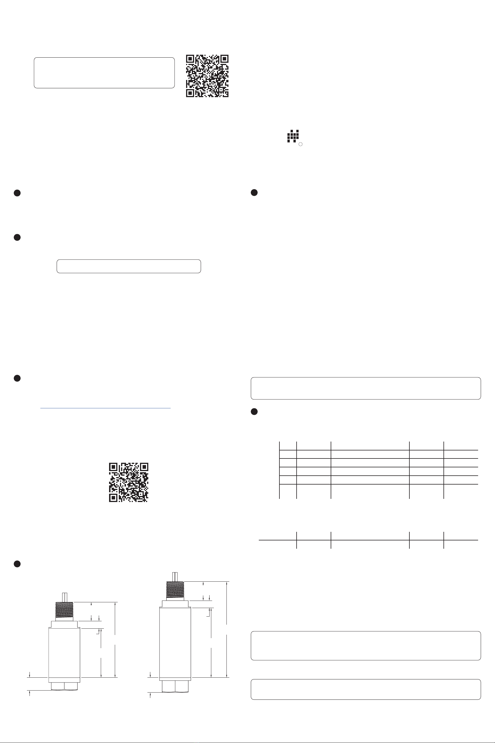
4Dimensions
NOTE: Scan the QR code to the right to see the full
user manual on your tablet or smartphone. Or visit
www.apgsensors.com/support to nd it on our website.
Part # 200126
Doc #9005324 Rev A2
Each label comes with a full model number, a part number, and a serial number. The model
number for the PT-405 will look something like this:
The model number correlates with all the congurable options and tells you exactly what you have.
Compare the model number to the options on the datasheet to identify your exact conguration.
You can also call us with the model, part, or the serial number and we can help you.
The label also includes the pinout, as does this installation guide.
You’ll also nd all hazardous certication information on the label.
SAMPLE: PT-405-L1-5000-PSIS-E60-5-P5-N0-M2-S2
Series PT-405 pressure transmitters oer reliability over a wide range of pressures and in harsh
industrial conditions and hazardous locations. They are certied explosion proof for hazardous
areas in the US and Canada by CSA for Class 1, Division 1 environments.
1Description
2How To Read Your Label
3Warranty
PT-405 Short Can (E60 option)
with NPTF process connection
Total length of PT-405 depends on selected process connection
IMPORTANT: Some Modbus manufacturers use reversed Tx+/Tx- pins. When connecting to
your system, ensure A to A and B to B connections.
2.35"
[59.7mm]
0.35"
[8.9mm]
0.91"
[23.05mm]
0.61"
[15.45mm]
0.71"
[18.1mm]
3.33"
[84.6mm]
0.35"
[8.9mm]
0.91"
[23.05mm]
3.61"
[91.6mm]
4.59"
[116.5mm]
PT-405 Long Can (E60L option)
with NPTF process connection
PT-405 Series Pin Out Table
Pigtail
4-20 mA 0-5 / 0.5-4.5 / 1-5 VDC 0-10 VDC RS-485
Red + Excitation + Excitation + Excitation + Excitation
Grn No wire + Output + Output B (Tx-)
Wht No wire - Output - Output A (Tx+)
Blk - Excitation - Excitation - Excitation - Excitation
Grn /
Ylw
Case
Ground
Case Ground Case
Ground
Case
Ground
N/C indicates no connection
For alternate pinouts, please consult factory
PT-405 Series Supply Power Table
4-20 mA 0-5 / 0.5-4.5 / 1-5 VDC 0-10 VDC RS-485
Power Supply 9-28 VDC 9-28 VDC 12.5-28 VDC 9-28 VDC
DANGER: Incorrectly connecting your PT-405 Pressure Transmitter to your control system
could result in injury or death.
IMPORTANT: Incorrectly connecting your PT-405 Pressure Transmitter to explosion proof
conduit, or using unapproved conduit, will void the protection rating of your PT-405.
7Zero Trimming
• Remove unit from Hazardous Location prior to performing Zero Trimming procedure.
• Remove the protective screw.
• Ensure that the transducer is at 0 psig or 0 psia (vacuum if absolute). For compound ranges,
i.e. -15 psi to 30 psi, the 4 mA, 0 V, 0.5 V, or 1 V set point is also at vacuum.
• Using a jeweler’s screwdriver or a suitable instrument, adjust the “Z” pot until you have a 4
mA, 0 V, 0.5 V, or 1 V output.
NOTE: You may also return the transducer to the factory for repair and/or adjustment.
IMPORTANT: Do not make changes to the Span adjustment (the “S” pot to the right, see
Figure 7.1) as part of the zero trimming. The Span should only be changed as part of the
recalibration of a gauge with a known pressure source.
Figure 7.1
Zero & Span
Adjustment
8Re-Calibration
This procedure requires a known pressure source of at least ±0.1% accuracy in order to fully utilize
the accuracy potential of the transducer. (If not available, you can return it to the factory for re-
calibration.)
• Remove Unit from Hazardous Location prior to recalibration.
• Ensure that the transducer is at 0 psig or 0 psia (vacuum if absolute), and adjust zero as per
instructions for zero trimming.
• Apply full scale pressure to the pressure port and adjust the Span (“S”) pot (on the right of
Figure 7.1) until the full scale signal is reached.
• Re-check zero and re-adjust the zero (“Z”) pot if required
• Repeat previous two steps until no further adjustment is required.
NOTE: You may also return the transducer to the factory for repair and/or adjustment.
9General Care
Your pressure transmitter is very low maintenance and will need little care. As long as it was
installed correctly, it will need very little care and maintenance. However, in general, you should:
• Keep the sensor and the area around it generally clean.
• Avoid applications for which the sensor was not designed, such as extreme temperatures,
contact with incompatible corrosive chemicals, or other damaging environments.
• Inspect the threads whenever you remove the sensor from duty or change its location.
• Avoid touching the diaphragm. Contact with the diaphragm, especially with a tool, could
permanently shift the output and ruin accuracy.
• Cleaning the diaphragm or the diaphragm bore should be done with extreme care. If using a
tool is required, make sure it does not touch the diaphragm.
10 Repair Information
If your pressure transmitter needs repair, contact us via email, phone, or online chat on our
website. We will issue you an RMA number with instructions.
• Phone: 888-525-7300
• Email: [email protected]
• Online chat at www.apgsensors.com
11 Removal Instructions
Removing your pressure transducer from service must be done with care. It’s easy to create an
unsafe situation, or damage your sensor, if you are not careful to follow these guidelines:
• Make sure the pressure is completely removed from the line or vessel where your sensor is
installed. Follow any and all procedures for safely isolating any media contained inside the line
or vessel.
• Remove the sensor with an appropriately sized wrench (per your process connection).
• Clean the sensor’s threads of any sealant compound or tape. Inspect the threads and the
diaphragm for any damage.
• Store your sensor in a dry place between -40° F and 180° F.
DANGER: Removing the pressure transmitter while there is still pressure in the line or
vessel could result in injury or death.
IMPORTANT: Do not adjust Zero or Span potentiometer while your PT-405 is installed in a
Hazardous Location. Removing the protective screws to access the potentiometers invalidates
the Hazardous Location approvals until they are replaced.
DANGER: Protective screws must be replaced using 28 oz-in of torque to create seal. DANGER: Removing the pressure transmitter while there is still pressure in the line or
vessel could result in injury or death.

Other APG Transmitter manuals

APG PT-500 Series User manual

APG

APG PT-500 Series User manual

APG HU-L24 User manual

APG

APG HU-L24 User manual

APG True Echo PRS Series User manual

APG

APG True Echo PRS Series User manual

APG PT-400 Series User manual

APG

APG PT-400 Series User manual

APG PT-510 Series User manual

APG

APG PT-510 Series User manual

APG PT-300 User manual

APG

APG PT-300 User manual

APG PT-400 Series User manual

APG

APG PT-400 Series User manual

APG PT-400 Series User manual

APG

APG PT-400 Series User manual

APG PT-500 Series User manual

APG

APG PT-500 Series User manual

APG True Echo GWR200 User manual

APG

APG True Echo GWR200 User manual

APG PT-405 Series User manual

APG

APG PT-405 Series User manual

APG PT-300 User manual

APG

APG PT-300 User manual

APG PT-500 Series User manual

APG

APG PT-500 Series User manual

APG PT-500 Series User manual

APG

APG PT-500 Series User manual

APG PT-400 Series User manual

APG

APG PT-400 Series User manual

Popular Transmitter manuals by other brands

Codan 3031 user guide

Codan

Codan 3031 user guide

EnOcean PTM 215ZE user manual

EnOcean

EnOcean PTM 215ZE user manual

Greystone CMD5B5 Series installation instructions

Greystone

Greystone CMD5B5 Series installation instructions

infobit WP70-T user manual

infobit

infobit WP70-T user manual

Evikon PluraSens E2648-CO2 user manual

Evikon

Evikon PluraSens E2648-CO2 user manual

YOKOGAWA EJX110B user manual

YOKOGAWA

YOKOGAWA EJX110B user manual

Anywave ATSC 560W DTV quick start guide

Anywave

Anywave ATSC 560W DTV quick start guide

PureTools PT-HDBT-702-TX user manual

PureTools

PureTools PT-HDBT-702-TX user manual

Aluprof DC1675 Programming instructions

Aluprof

Aluprof DC1675 Programming instructions

Omega DRST-AC user guide

Omega

Omega DRST-AC user guide

ProtoArc RGB C1 user manual

ProtoArc

ProtoArc RGB C1 user manual

EUTECH INSTRUMENTS 2-WIRE PHORP TRANSMITTER operating instructions

EUTECH INSTRUMENTS

EUTECH INSTRUMENTS 2-WIRE PHORP TRANSMITTER operating instructions

HumanTechnik lisa operating instructions

HumanTechnik

HumanTechnik lisa operating instructions

Emerson Rosemount 2051G quick start guide

Emerson

Emerson Rosemount 2051G quick start guide

HITROL HT-100CT-2 Series instruction manual

HITROL

HITROL HT-100CT-2 Series instruction manual

Sennheiser HDI 406 - ANNEXE 69 manual

Sennheiser

Sennheiser HDI 406 - ANNEXE 69 manual

Advanced Axis D9068 Installation & operation manual

Advanced

Advanced Axis D9068 Installation & operation manual

Foxtech XLINK-30 user manual

Foxtech

Foxtech XLINK-30 user manual

manuals.online logo
manuals.online logoBrands
  • About & Mission
  • Contact us
  • Privacy Policy
  • Terms and Conditions

Copyright 2025 Manuals.Online. All Rights Reserved.