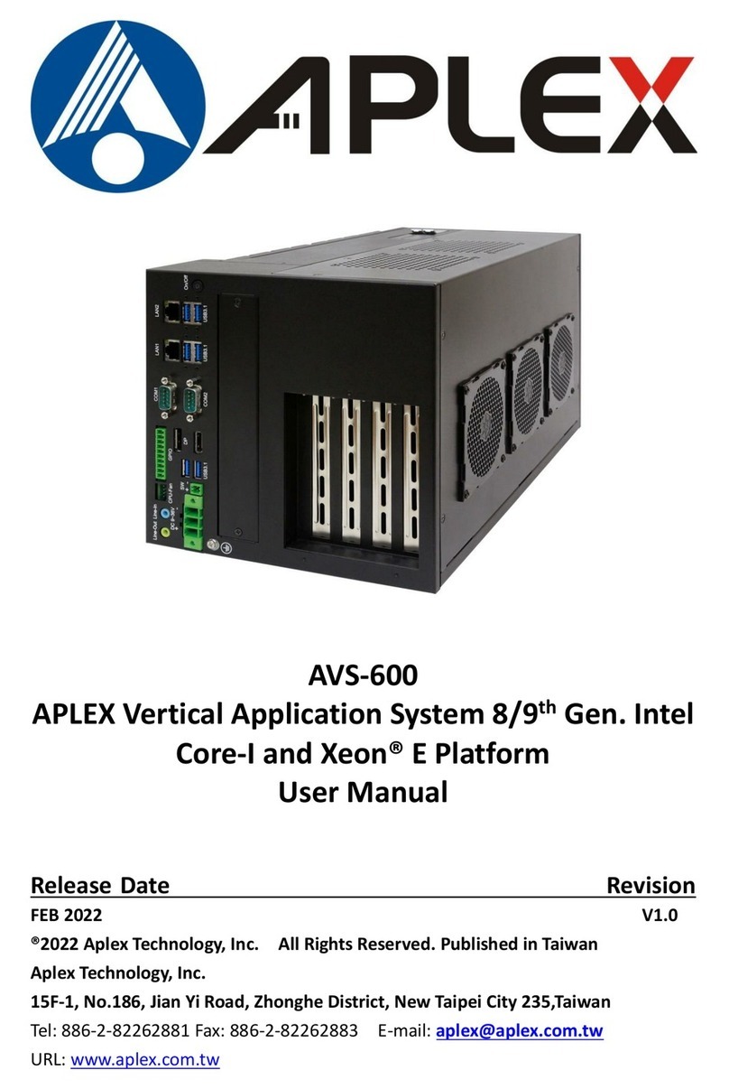
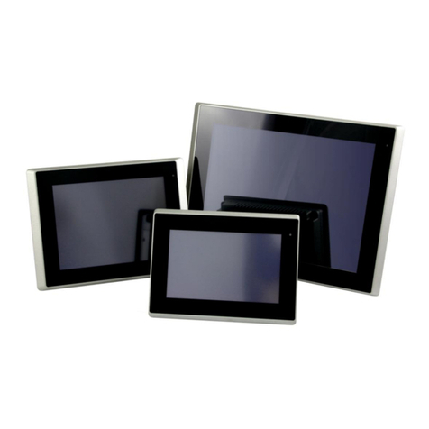
Aplex AUHMI Series User manual

ACS-500 Box PC User Manual
1
Revision History
Reversion
Date
Description
1.0
2024/01/11
Initiation

ACS-500 Box PC User Manual
2
Warning!_______________________________________
Caution
Risk of explosion if the battery is replaced with an incorrect type.
Batteries should be recycled where possible. Disposal of used batteries must be in accordance with local
environmental regulations.
Disclaimer
This information in this document is subject to change without notice. In no event shall Aplex Technology
Inc. be liable for damages of any kind, whether incidental or consequential, arising from either the use or
misuse of information in this document or in any related materials.
This equipment generates uses and can radiate radio frequency energy and if not installed and
used in accordance with the instructions manual, it may cause interference to radio communications.
It has been tested and found to comply with the limits for a Class A computing device pursuant to FCC
Rules, which are designed to provide reasonable protection against such interference when operated
in a commercial environment. Operation of this equipment in a residential area is likely to cause
interference in which case the user at his own expense will be required to take whatever measures
may be required to correct the interference.
Electric Shock Hazard – Do not operate the machine with its back cover removed. There are dangerous
high voltages inside.

ACS-500 Box PC User Manual
3
Safety Precautions
Follow the messages below to prevent your systems from damage:
◆ Avoid your system from static electricity on all occasions.
◆ Prevent electric shock. Don‘t touch any components of this card when the card is power-on.
Always disconnect power when the system is not in use.
◆ Disconnect power when you change any hardware devices. For instance, when you connect a
jumper or install any cards, a surge of power may damage the electronic components or the
whole system.

ACS-500 Box PC User Manual
4
Table of Contents
Revision History.................................................................................................................................1
Warning!_______________________________________......................................................................2
Safety Precautions .............................................................................................................................3
Chapter 1 System Product ............................................................................................................6
1.1 Features .................................................................................................................................6
1.2 Specifications ..........................................................................................................................6
1.3 COM port definition.................................................................................................................8
1.4 Power Consumption and PoE Application...................................................................................9
1.5 Dimensions ...........................................................................................................................10
1.6 Brief Description of ACS-500 Series..........................................................................................11
1.7 Wall Mount...........................................................................................................................12
1.8 Battery Kit Installation............................................................................................................13
1.9 Warning of HDMI/DP port insert .............................................................................................14
Chapter 2 Hardware...................................................................................................................15
2.1 Specifications ........................................................................................................................15
2.2 Board Overview.....................................................................................................................18
2.3 Jumpers Setting and Connectors .............................................................................................20
Chapter 3 BIOS Setup Description.........................................................................................28
3.1 Overview ..............................................................................................................................28
3.2 Main Settings ........................................................................................................................30
3.3 Advanced Settings .................................................................................................................31
3.4 Chipset Settings..................................................................................................................41
3.5 Security Settings....................................................................................................................46
3.6 Boot Settings.........................................................................................................................48
3.7 Save & Exit Settings................................................................................................................49
Chapter 4 Installation of Drivers.............................................................................................51
4.1 Intel Chipset..........................................................................................................................52
4.2 Intel® HD Graphics Chipset................................................................................................54
4.3 Realtek HD Audio Driver Installation........................................................................................56
4.4 Intel LAN Driver .....................................................................................................................57
4.5 Intel® Serial I/O .....................................................................................................................59
4.6 Intel® Management and Security Status Installer ......................................................................62
4.7 Intel® Management Engine Components.......................................................................................63
4.8 Intel® HID Event Filter..................................................................................................................65

ACS-500 Box PC User Manual
5
List of Figures
FIGURE 1 DIMENSIONS OF ACS-500............................................................................................................................................... 10
FIGURE 2 AUHMI-910C MB BOX KIT ATTACHES TO FRONT KIT...................................................................錯誤! 尚未定義書籤。
FIGURE 3 HDMI/DP PORT INSERT INSTRUCTION WARNING ............................................................................................................ 14

ACS-500 Box PC User Manual
6
Chapter 1 System Product
1.1 Features
⚫Intel® 11th Gen. Fanless BOX PC
⚫Fanless design
⚫DC 9~36V wide-ranging power input
⚫2 x 260-pin DDR4 SO-DIMM up to 64GB 3200MHz
1.2 Specifications
ACS-500
System
CPU
Intel 11th Gen. Core™ i7/i5/i3/Celeron SoC Processors
Core i7-1185G7E (4C, 1.7GHz, up to 4.4GHz, TDP-up 28W) by project
Core i5-1145G7E (4C, 1.5 GHz, up to 4.1GHz, TDP-up 28W)
Core i3-1115G4E (2C, 2.2 GHz, up to 3.9GHz, TDP-up 28W)
Celeron® 6305UE(2C, 1.80GHz, TDP 15W)by project by project
Chipset
SoC
Memory
2 x DDR4 SO-DIMM slot, 3200MHz, up to 64GB
TPM
Onboard TPM2.0
IO Port
USB
4 x USB 3.2 type A
Serial/Parallel
1 x RS-232 pin1 RTS/5V/12V selectable via jumper (COM1),
1 x RS-232/422/485 port (COM2), in 1x DB9 connector (COM1_2)
Audio
1 x Audio Line Out
LAN
2 x GbE LAN RJ-45
Power
1 x 3-pin DC Power Input terminal
1 x 2-pin connector for power on/off button
Display port
1 x DP/HDMI (co-lay)
Option
⚫TB-528 Series:
1. 4 x USB 2.0 type A (TB-528U4)
2. 4 x USB 2.0 type A + 1 x Mini-PCIe + 1 x SIM slot (TB-528U4ME1)
3. 2 x COM(RS-232) (TB-528C2)
4. 1 x COM*RS-232) + 2 x USB 2.0 (TB-528C1U2)
5. 1 x COM(RS-232) + 2 x USB2.0 + 1 x Power Button(TB-528C1U2P1)
6. 2 x CAN (TB-528CAN2)
7. 2 x COM(RS-232) + 1 x Mini-PCIe slot + 1 x SIM slot(TB-528C2ME1)
8. 2 x COM (RS-422/485, isolated) (TB-528C2I)
9. 1 x LAN + 2 x USB 2.0 type A (TB-528E1U2)

ACS-500 Box PC User Manual
7
10. 1 x LAN+2 x USB2.0+ 45WPOE(TB-528E1U2UPOE)
◆Backup Battery Pack (exclusive for high brightness model and no TB-528 series at the same
time)
◆1 x 2W Speaker(exclusive 528 series and backup battery)
◆Auto Dimming (Exclusive LED indicator)
◆GPIO (4xDI, 4xDO)
◆WIFI (Through M.2 E Key)
◆Cable Cover (above 15.6”)
(Speaker, TB-528 series and Backup Battery, choose one from three, do not use
meanwhile)
Storage Space
Storage
1 x M.2 2280 M Key (PCIex4/SATA III), support NVME SSD
1 x 2.5” SATAIII HDD (Option, exclusive of TB528 series, battery)
Expansion
Expansion Slot
1 x M.2 2230 E-Key socket for optional Wi-Fi/BT Module (PCIex2+USB 2.0)
1 x Full-size Mini-PCIe slot
1 x Nano SIM card holder
Wireless LAN and Antenna
Wireless LAN
Wifi 5/6e viaM.2 Key module card (option)
LTE 4G, WWAN module
Antenna
4 x SMA-female connector’s holes for external antenna(default 2 antenna)
Power
Power Input
DC 9~36V
Power on AT/ATX supported, default AT mode
⚫AT: Directly PWR on as power input ready
⚫ATX: Press button to PWR on after power input ready
Support POE++ through TB-528E1U2UPOE (depends on real power consumption)
Backup Battery
Backup battery
3250mAH(option)
*When the Backup battery is installed; it cannot run full loading program; it may cause the
system shot down
Mechanical
Mechanical
Construction
Aluminum die-casting heat-sink/ black steel for chassis
Front Bezel Metal
Aluminum
Mounting
Wall Mount
Chassis Color
Black
IP Rating
IP30(TBD)
Net Weight (kg)
1.5
Operating System Support
OS Support
Windows 10 IoT

ACS-500 Box PC User Manual
8
Windows 11
Linux Ubuntu 18.04 with Kernel 5.0
Linux Ubuntu 20.04
Environmental
Operating
Temperature
-20℃ to 60℃ (-30℃ to 70℃ for option)
Storage Temperature
-30~80°C
Humidity
10 to 90% @ 40°C, non-condensing
Certification
CE / FCC Class A, RoHS/REACH Compliant
1.3 COM port definition
Pin#
COM1
(RS232)
COM2
(RS232)
COM2
(RS422)
COM2
(RS485)
1
RTS/5V/12V
2
RX
3
TX
4
CTS
5
GND
GND
6
TX
RX+
7
RX-
8
TX-
D-
9
RX
TX+
D+
1x RS232, pin1 RTS/5V/12V selectable via jumper (COM1), jumper setting please refer to the 18. JP2:
1x RS232/422/485 port(COM2), in 1xDB9 connector (COM1_2)
2507009001000000
COM port Y cable
DSUB/DSUB 9P(F) TO (M)×2 FOR Volt /RS232 L=10cm
Default
4507009001000001
COM port Y cable (optional)
DSUB/DSUB 9P(F) TO (M)×2 FOR RTS L=10cm
Optional
WARNING: If the wrong Y cable is used, it may damage the device

ACS-500 Box PC User Manual
9
1.4 Power Consumption and PoE Application
Max power consumption of each model
Model
Max Power
Consumption
PoE++(45W)
ACS-500
27.44
y*
* Max Power Consumption: Backlight bright setting 100%,+Turbo on+ System full loading with full
rear IO connectors.
* Power consumption may have 10% tolerance difference due to different MB, parts, test instrument,
and so on.
* y* means: system turbo off+ rear IO no loading+ LED backlight down to 70%, and the PSE cable
connect to the system needs to be shorter than 50m. If you need some IO loading, please find your
sales representative to discuss.
* y* does not apply in Linux OS.
* We suggest to use the adapter that Aplex approved. If you would like to adopt your own power supply
or adapter, please add another 20-30% from the above power consumption to make sure the system
can work correctly.

ACS-500 Box PC User Manual
10
1.5 Dimensions
Figure 1 Dimensions of ACS-500

ACS-500 Box PC User Manual
11
1.6 Brief Description of ACS-500 Series
The ACS-500 Industrial BOX PC in AUHMI-9XXC series, which comes with Aluminum heat-sink and
black steel chassis. Intel 11th Generation Core i3/i5/i7 CPU Processors with two SO-DIMM DDR4 slot, up to
64GB 3200 MHz are installed in this model. The system supports DC 9~36V wide-ranging power input and
IP30 for dust and water protection, which is ideal for Industrial Automation & Factory Automation.
Furthermore, AUHMI-9xxC Series are capable of expanding the function by option expansion I/O boards, TB-
528 series, includes Mini-PCIe, CAN bus, POE, USB, and isolation I/O module to improve competitive
advantage through providing critical flexibility and expansibility for the variety of application and
requirement.
Figure 2 Overview of ACS-500

ACS-500 Box PC User Manual
12
1.7 Wall Mount
The ACS-500 is designed to be Wall Mounted as shown in Picture below.
Figure 3 ACS-500 Mounting

ACS-500 Box PC User Manual
13
1.8 Battery Kit Installation
Step1: Insert the battery kit to the MB box kit and screw it with 4pcs M3x6 screws.
Step2: Connect the battery cable to the MB connector.

ACS-500 Box PC User Manual
14
1.9 Warning of HDMI/DP port insert
Important:
Please be cautious when inserting an HDMI cable into the HDMI/DP port. The HDMI male
connector shall align to the left of the port as illustrated here. The insertion is fairly effortless and
please reframe from forcing the insertion to prevent damage.
Figure 32 HDMI/DP port insert instruction warning

ACS-500 Box PC User Manual
15
Chapter 2 Hardware
SBC-7125 is an industrial motherboard developed on the basis of Intel Core I Processors,
which provides abundant peripheral interfaces to meet the needs of different customers.
Also, it features dual RJ45 connectors, 6-COM ports and one M.2 M-Key configuration,
one DP/HDMI combo connector, one LVDS interface. To satisfy the special needs of high-
end customers, 1 x M.2 E-Key slot and 1 x mini PCIe richer extension functions. The
product is widely used in various sectors of industrial control.
2.1Specifications
Specifications
Board Size
155mm x 125mm
CPU Support
Intel® Core™i3-1115G4E(2C/4T, 2.20 up to 3.9GHz)
Intel® Core™i5-1145G7E(4C/8T,1.50 up to 4.1GHz)
Intel® Core™i7-1185G7E(4C/8T 1.70 up to 4.4GHz)
Intel® Celeron 6305UE(2C/2T, 1.80 GHz)
Chipset
SOC
Memory
Support
2x 260pin dual channel SO-DIMM up to 64GB DDR4 3200MHz
Graphics
Intel® Iris® X (i5-1145G7E )
Intel® UHD Graphics (i3-1115G4E)
Display Mode
1 x DP/HDMI Combo connector(auto detect)
Support
Resolution
Up to 7680 x 4320 for DP 1.4a @ 60Hz
Up to 4096 x 2304 for HDMI 2.0b @ 60Hz
Up to 4096 x 2304 for eDP @ 60Hz
Dual Display
HDMI + DP
Super I/O
Nuvoton NPCT750
BIOS
AMI UEFI
Wake on LAN
Support wake on LAN
Storage
1 x SATAIII Connector (7Pin)
1 x M.2 M-Key(PCIe x4/SATAIII Auto Detect),Support 2280
NVME SSD
Ethernet
1 x Twin RJ45 Connector
Intel® i219-LM GbE LAN, support vPRO
Intel® i210-AT, GbE LAN
USB
4 x USB 3.2 Gen1x1 via 2xUSB Type A Stack port
2 x Dual USB type A connector

ACS-500 Box PC User Manual
16
USB power control by BIOS GPIO (enable/disable)
Without re-driver IC
1 x USB 2.0 via 180°Pitch 2.0mm 2x5Pin DIP type header
2 USB2.0 signal
1 x SATA 3.0 connector: Data transfer rate up to 6Gb/s
1 x SATA power connector :90°pitch 2.0mm 2x5 pin male
header
Serial
1 x DB9 Male Connector
◼1x RS232 port, Pin1 w/5V/12V/RTS select (COM1)
◼1x RS232/RS422/RS485 port (COM2)
Digital I/O
8-bit digital I/O with 5V/12V selectable via jumper, via 180°pitch
2.0mm 2x5pin male header
4-bit digital Input
4-bit digital Output
RTC Battery
Support RTC CR2477 battery via 180°pitch 1.25mm 2-pin
wafer
Smart battery
Support 3S1P 18650 battery pack
*Battery power input needs to support AT/ATX power mode as
well
Audio
1 x Line out via 3.5mm audio jack connector
Mic-in and speaker out (support 1x2w stereo speakers) via 180°
pitch 2.0mm 2x5pin male header
Expansion Bus
1 x full-size mini-PCI-express slot for M-PCIE and USB signal
1 x M.2 2230 E-Key slot
1 M2 standoff
Support PCIe x1 and USB signal
Support Intel® CNVi module and Intel® wPro
1 x M.2 2280 M-Key slot
Support PCIe x1 and USB signal

ACS-500 Box PC User Manual
17
Support 1 clamshell nano-SIM slot
1 x Nano SIM slot via onboard micro SD+ Nano SIM combo slot
for mini-PCIe
Buzzer
1 x Onboard buzzer
Button
1 x Power Button via pitch 2.5mm 2pin terminal block and 180°
pitch 2.0mm 2pin wafer
1 x Reset Button via 180°pitch 2.0mm 2pin wafer
Power
Management
1 x Power connector
DC 9~36V power range
Switches and
LED Indicators
1 x Power on/off switch (BT1/CN2/CN3)
1 x Ambient light sensor for auto dimming support via 180°pitch
1.25mm 2pin wafer
1 x HDD LED status
1 x Power LED status
Signals to LCD
LVDS(default)
eDP(option)
LVDS and eDP are selectable via BOM control, support LCD
parameter auto detection
Backlight Control & Power, support auto dimming
1xUSB2.0 for PCAP touch screen
Backlight
1 x 180°pitch 2.0mm 6pin wafer for high brightness backlight
control and power, support auto dimming
External I/O
port
1 x COM Ports (COM1-1/COM1-2)
4 x USB 3.2 Gen1 Ports (stack)
2 x RJ45 GbE LAN Ports
1 x DP Port
1 x Audio Jack (Line out)
TPM
TPM 2.0 via SPI interface TPM 2.0 solution
*Note: Only support Windows 10 IOT
Temperature
Operating: -20℃to 60℃
Storage: -40℃to 80℃
Humidity
10% - 95%, non-condensing, operating
Watchdog Timer
255 levels
EMI/EMS
Meet CE/FCC class A
OS Support
Windows 10, Windows 11
Linux Ubuntu 20.04 and above

ACS-500 Box PC User Manual
18
2.2 Board Overview
2.2.1 Board Top View
(units :mm)
1
Buzzer
2
ESPI Header
3
Battery Header
4
SATA0
5
SATA Power
6
TB-528 2x30 Pin Header
7
Clear CMOS
8
RTC Battery
9
SPI
10
DC IN Header
11
Reset Button
12
Power Button
13
DP/HDMI
14
▲USB2_3/4
▼USB3_3/4
15
▲USB2_1/2
▼USB3_1/2
16
LAN1 & LAN2
17
COM Port
18
Audio

ACS-500 Box PC User Manual
19
2.2.2 Board Bottom View
19
USB Header
20
SIM Card Slot
21
EC Debug
22
DIO Power Select (CN1_DIO)
23
DIO
24
Audio Header
This manual suits for next models
1
Table of contents
Other Aplex Industrial PC manuals