Aplex ACS-2330 User manual

ACS-2330/2332
Intel 6th Gen. Core i Fanless Box PC
User Manual
Release Date Revision
May.2017 V1.1
®2017 Aplex Technology, Inc. All Rights Reserved. Published in Taiwan
Aplex Technology, Inc.
15F-1, No.186, Jian Yi Road, Zhonghe District, New Taipei City 235, Taiwan
Tel: 886-2-82262881 Fax: 886-2-82262883 URL: www.aplextec.com

ACS-2330/2332 User Manual
1
Revision History
Reversion
Date
Description
1.0
2017/02/18
Official Version
1.1
2017/05/03
Modify product image
Remove 1xmSATA
Modify COM port position
Modify SSD spec. up to 32GB
Add LAN LED light description for LAN1~4

ACS-2330/2332 User Manual
2
Warning!________________________
Disclaimer
This information in this document is subject to change without notice. In no event
shall Aplex Technology Inc. be liable for damages of any kind, whether incidental or
consequential, arising from either the use or misuse of information in this
document or in any related materials.
Caution
Risk of explosion if the battery is replaced with an incorrect type.
Batteries should be recycled where possible. Disposal of used batteries must be in
accordance with local environmental regulations.
This equipment generates, uses and can radiate radio frequency energy and
if not installed and used in accordance with the instructions manual, it may cause
interference to radio communications. It has been tested and found to comply
with the limits for a Class A computing device pursuant to FCC Rules, which are
designed to provide reasonable protection against such interference when
operated in a commercial environment. Operation of this equipment in a
residential area is likely to cause interference in which case the user at his own
expense will be required to take whatever measures may be required to correct
the interference.
Electric Shock Hazard –Do not operate the machine with its back cover removed.
There are dangerous high voltages inside.

ACS-2330/2332 User Manual
3
Packing List
Accessories (as ticked) included in this package are:
□Adaptor
□Driver & manual CD disc
□Other.___________________(please specify)

ACS-2330/2332 User Manual
4
Safety Precautions
Follow the messages below to prevent your systems from damage:
◆Avoid your system from static electricity on all occasions.
◆Prevent electric shock. Don‘t touch any components of this card when
the card is power-on. Always disconnect power when the system is not
in use.
◆Disconnect power when you change any hardware devices. For instance,
when you connect a jumper or install any cards, a surge of power may
damage the electronic components or the whole system.

ACS-2330/2332 User Manual
5
Table of Contents
Revision History…………………………………………………………………………………………………….1
Warning/Disclaimer............................................…………………………….……………………2
Packing List…………………………………….…………………………………………………....................3
Safety Precautions…………………………………….…………….…..……………………....................4
Chapter 1 Getting Started
1.1 Features……..…………………..………………………...…………………………………...7
1.2 Specifications…..………………...………………………………………………..………….7
1.3 Dimensions……..…………………....…………………………………………………..…...9
1.4 Brief Description of ACS-2330/2332…..…..……………………………....…....10
Chapter 2 Hardware
2.1 Motherboard Introduction…………………….....……………………………….....12
2.2 Specifications…………………………..…………..……………………………..…………12
2.3 Jumpers and Connectors Location……….………………………………………...16
2.4 Jumpers Setting and Connectors…………..………………………………….…...18
Chapter 3 BIOS Setup
3.1 Operations after POST Screen…...……..…...………………………………………39
3.2 BIOS Setup Utility…………………………..…………………………………….………..39
3.3 Main Settings…………………………………....……………………………………..……40
3.4 Advanced Settings……………………………………….…………………………….....41
3.5 Chipset Settings………………………….………….………………………………….....46
3.6 Security Settings……..…………….……………..……….……………………….……..47
3.7 Boot Settings…..………..…………….…….………….……………………………..…..49
3.8 Save & Exit Settings………………………..…………..…………………………….....50
Chapter 4 Installation of Drivers
4.1 Intel(R) 100 Series Chipset Driver…......….………..…….………………………52
4.2 Intel(R) HD Graphics 530 Chipset Driver…………………….…………….......56
4.3 Realtek ALC269 HD Audio Driver…...………………………..…………..….…...60
Figures
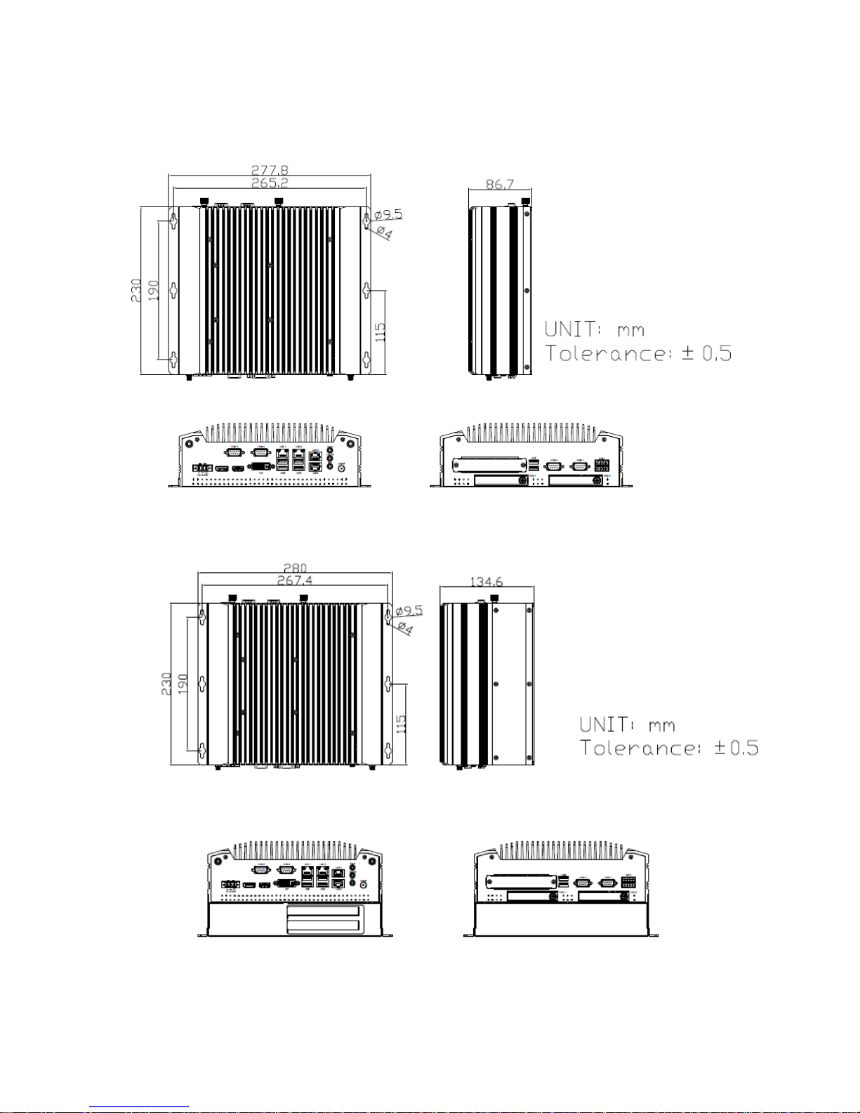
Figure 1.1: Dimensions of ACS-2330………..……....…….……………………………..9
Figure 1.2: Dimensions of ACS-2332..….........……………..…..……………….……9
Figure 1.3: Front view of ACS-2330………….……….………………………………….10
Figure 1.4: Front view of ACS-2332………….……….………………………………….10

ACS-2330/2332 User Manual
6
Figure 1.5: I/O rear view of ACS-2330………….……….…………………………….11
Figure 1.6: I/O rear view of ACS-2332………….………….………………………….11
Figure 2.1: Motherboard Dimensions…………………………………………………..15
Figure 2.2: Jumpers and Connectors Location-Board Top……………………..16
Figure 2.3: Jumpers and Connectors Location-Board Bottom……………….17

ACS-2330/2332 User Manual
7
Chapter 1 Getting Started
1.1 Features
Intel 6th Gen. Skylake Core i3/i5/i7 CPU
2 x SO-DIMM, up to 32GB
Easy accessible storage design
Fanless Design
Multi-expansion slot
Support 2 x PCIe slot for ACS-2332
Three independent display ports
Wide range DC 9~36V power input
1.2 Specifications
ACS-2330
ACS-2332
System
CPU
Intel 6th Gen. Skylake Core i3/i5/i7 CPU
Chipset
Intel 100 series Chipset(H170)
Memory
2 x 260-pin SO-DIMM up to 32GB DDR4 2133/2400 MHz
Outside IO Port
USB:
Front: 4 x USB 3.0 type A, Rear: 2 x USB 2.0 type A
Serial/Parallel:
Front: 2 x RS-232/422/485, COM3/COM4, default RS-232
Rear: 2 x RS-232 , COM1/COM2
Audio:
1 x Line-in, 1 x Line-out, 1 x Mic
Display Interface:
1 x Display port, 1 x DVI-I, 1 x HDMI
GPIO:
1 x 4-in/4-out digital I/O, 1-5V, 1-GND
POWER:
1 x 3-pin DC power input terminal, 1 x power button with light
Storage Space
Storage
2 x 2.5” SATA3 HDD bay (Easy accessible)
Expansion
Expansion Slot
3 x Mini PCIe slots full size (one shared with mSATA)
(Only for ACS-2332) 2 x PCIe slot via TB-554E41E11:1 x PCIe x4 or 2 x
PCIe x1 slot for option
Wireless LAN

ACS-2330/2332 User Manual
8
Wireless LAN
802.11 b/g/n via Mini-PCIe module card half size
(Optional) Rear side design Antenna hole
Power
Power Input
DC 9~36V power input
Power Consumption
MAX: 56.3W
MAX: 60.4W
Mechanical
Construction
Plating Titanium Gray Aluminum Hearsink and Black Steel Chassis
Mounting
Wall Mount
Dimensions
277.8 x 230 x 86.7 mm
280 x 230 x 134.6 mm
Net Weight
4.5 Kg
5.5 kg
Environmental
Operating
Temperature
0~50°C
Storage Temperature
-40~85°C
Storage Humidity
10 to 90% @ 40°C , non-condensing
Certification
CE / FCC Class A
Operating System
Support
Windows Embedded 8.1 Industry Pro,
Windows Embedded 8 Standard Pro,
Windows 10 IOT 2016

ACS-2330/2332 User Manual
9
1.3 Dimensions
Figure 1.1: Dimensions of ACS-2330
Figure 1.2: Dimensions of ACS-2332

ACS-2330/2332 User Manual
10
1.4 Brief Description of ACS-2330/2332
The ACS-2330/2332 is a fanless design high-efficiency BOX PC, powered by Intel 6th
Gen. Skylake Core i3/i5/i7 CPU and supports 2 x SO-DIMM DDR4 slots 2133/2400
memory. It comes with 4 x USB 3.0 type A, 2 x USB 2.0 type A, 1 x Line-in, 1 x
Line-out, 1 x Mic. It supports 2 x 2.5” SATA3 HDD space which is easy accessible
designed and wide range DC 9~36V power input. The model has 3 x Mini PCIe full
size (one shared with mSATA) slots for expansion. The model is plating titanium gray
aluminum heatsink and black steel chassis design, and can be wall mounted. The
ACS-2330/2332 works very well along with any of our display series and it absolutely
can provide an easy way to perform control and field maintenance.
Figure 1.3: Front view of ACS-2330
Figure 1.4: Front view of ACS-2332

ACS-2330/2332 User Manual
11
Figure 1.5: I/O rear view of ACS-2330
Figure 1.6: I/O rear view of ACS-2332

ACS-2330/2332 User Manual
12
Chapter 2 Hardware
2.1 Motherboard Introduction
SBC-7113 is a Non-standard industrial motherboard developed on the basis of Intel
H170, which provides abundant peripheral interfaces to meet the needs of different
customers. Also,it features four GbE ports, 6-COM ports and two Mini PCIE
configuration. To satisfy the special needs of high-end customers, ADOtec designed
80Pin PCIe x4 expansion interface. The product is widely used in various sectors of
industrial control.
2.2 Specifications
Specifications
Board Size
214mm x 225mm
CPU Support
installing the 6th Generation intel Core i3/i5/i7 6xxxTE Processors (up
to 35W).
- Intel Core I3-6100TE 2.70GHz 35W
- Intel Core I5-6500TE 2.30 GHz (up to 3.30 GHz) 35W
- Intel Core I7-6700TE 2.40 GHz (up to 3.40 GHz) 35W
Chipset
Intel H170
Memory Support
2x SO-DIMM (260pins), up to 32GB DDR4 1866/2133MHz FSB
Graphics
Intel HD Graphics 530(I3-6100TE/I5-6500TE/I7-6700TE)
Display Mode
1x DVI-I interface
1x HDMI interface
1x DP interface
1x VGA interface
Support
Resolution
Up to 4096 x 2304 for HDMI
Up to 4096 x 2304 for Display Port
Up to 2560 x 1600 for DVI-I
Up to 1920 x 1200 for VGA
Three Display
HDMI + DVI-I + DP
HDMI + DVI-I +VGA(option)
DVI-I + DP + VGA(option)
Super I/O
Nuvoton NCT6106D

ACS-2330/2332 User Manual
13
BIOS
AMI/UEFI BIOS
Storage
2x SATA3.0 Connector (SATA1/SATA2)
1x MSATA Connector (M_SATA1)
Ethernet
4x PCIe GbE LAN by Intel 82574L
USB
4x USB 3.0/2.0 stack ports for external
(USB3.0:USB3-1/USB3-2/USB3-3/USB3-4)
(USB2.0:USB2-1/USB2-2/USB2-3/USB2-4)
2x USB 2.0 stack ports for external (USB_78)
3x USB 2.0 Pin header for MIO1 (USB11/USB12/USB13)
2x USB 3..0/2.0 Pin header for MIO2
(USB3.0:USB3-5/USB3-6, USB2.0:USB2-5/USB2-6)
1x USB 2.0 internal for M-PCIe1 (USB2-10)
1x USB 2.0 internal for M-PCIe2 (USB2-09)
1x USB 2.0 internal for M-SATA1 (USB2-14)
Serial
2x RS232/422/485 port, DB9 connector for external (COM1/COM2)
Pin9 w/5V/12V/Ring select
2x RS232 port, DB9 connector for external (COM3/COM4)
Pin9 w/5V/12V/Ring select
2x RS232/422/485 select header for internal MIO1 (COM5/COM6)
Digital I/O
8-bit digital I/O by Pin header
4-bit digital Input
4-bit digital Output
Battery
Support CR2477 Li battery by 2-pin header (1000mAh)
Audio
Support Audio via Realtek ALC269-VB HD audio codec
Support Line-out, Line-in,MIC-in by JACK (AUDIO1)
Support a stereo Class-D Speaker Amplifier with 2 watt per channel
output power, by 1x4-pin header (SPK1)
Keyboard /Mouse
PS2 K/B and Mouse by 1x6Pin Wafer connector
1x PS/2 keyboard
1x PS/2 mouse
Expansion
1x PCI-express x4 extend by 4x20 pin socket (PCIE_4X)
2x mini-PCI-express slot (M-PCIE1/MPCIE2)
1x CRT 2x5 Pin Header (VGA1)
Power
Management
1x 3-pin power input connector (Wide range DC+9V~36V)
DC5V/12V output by 1x4 pin Connectors

ACS-2330/2332 User Manual
14
Switches and
LED Indicators
Power on/off switch by MIO1 and MIO2
Power LED status by MIO1 and MIO2
HDD LED status by MIO2
Reset switch by MIO1
External I/O port
4x COM Ports (COM1/COM2/COM3/COM4)
4x USB 3.0 Ports (stack)
2x USB 2.0 Ports (stack)
4x RJ45 GbE LAN Ports
1x DVI-I interface
1x HDMI interface
1x Display Port
1x Audio Ports (Mic in,Line in,Line out)
SIM
1x SIM Socket
LPT
1x LPT Port by DF13-20P (LPT1)
Temperature
Operating: -20℃to 70℃
Storage: -40℃to 85℃
Humidity
10% - 90%, non-condensing, operating
Power
Consumption
12V/5.2A(Intel i5-6500TE 2.30 GHz Processor with 16GB DDR4/HDD)
EMI/EMS
Meet CE/FCC class A

ACS-2330/2332 User Manual
15
(units :mm)
Figure 2.1: Motherboard Dimensions

ACS-2330/2332 User Manual
16
2.3 Jumpers and Connectors Location
Figure 2.2: Jumpers and Connectors Location- Board Top

ACS-2330/2332 User Manual
17
Figure 2.3: Jumpers and Connectors Location- Board Bottom

ACS-2330/2332 User Manual
18
2.4 Jumpers Setting and Connectors
1. RTC1/SRTC1:
(2.0mm Pitch 1x2 Pin Header)CMOS clear jumper, CMOS clear operation will permanently reset
old BIOS settings to factory defaults.
Procedures of CMOS clear:
a) Turn off the system and unplug the power cord from the power outlet.
b) To clear the CMOS settings, use the jumper cap to close pins1 and 2 for about 3 seconds then
reinstall the jumper clip back to pins open.
c) Power on the system again.
d) When entering the POST screen, press the <DEL> key to enter CMOS Setup Utility to load
optimal defaults.
e) After the above operations, save changes and exit BIOS Setup.
2. BAT1 :
(1.25mm Pitch 1x2 wafer Pin Header) 3.0V Li battery is embedded to provide power for
CMOS.
3. PS_ON2:
(2.0mm Pitch 1x2 Wafer Pin Header),ATX Power and Auto Power on jumper setting.
4. PS_ON1:
(2.0mm Pitch 1x2 Wafer Pin Header) ,Power on/off, They are used to connect power switch

ACS-2330/2332 User Manual
19
button. The two pins are disconnected under normal condition. You may short them temporarily
to realize system startup & shutdown or awaken the system from sleep state.
5. PS_SW:
Power on/off button, They are used to connect power switch button.
Power LED Status. Green LED for Motherboard Power status.
6. DC_IN1:
(5.08mm Pitch 1x3 Pin Connector),DC9V ~ DC36V System power input connector。
Pin#
Power Input(DC_IN1)
Pin1
DC+9V~36V
Pin2
Ground
Pin3
FG
DC_IN1(Power Input)
JP5
DC+9V~36V
NC (Default)
DC12V only(*)
Option (BOM cost down)
7. JP5 (option):
(2.0mm Pitch 2x2 Pin Pin Header), DC12V System only power input jumper setting.
【
*please contact technical support
】
8. DC_OUT:
(2x2 Pin Connector),DC+12V and DC+5V System power output connector.
Pin#
Power output
Pin1
DC+12V(DC12V_S0)
Pin2
Ground
Pin3
Ground
Pin4
DC+5V(DC5V_S0)
This manual suits for next models
1
Table of contents
Other Aplex Industrial PC manuals

Aplex
Aplex ACS-2702 User manual

Aplex
Aplex AHMI-8 Series User manual

Aplex
Aplex AVS-600 User manual

Aplex
Aplex ACS-2160 User manual

Aplex
Aplex NV-266 C Series User manual

Aplex
Aplex AUHMI Series User manual

Aplex
Aplex AEx-2410 User manual

Aplex
Aplex AVS-301 User manual

Aplex
Aplex ARCHMI-8 H Series User manual
Popular Industrial PC manuals by other brands

Sintrones
Sintrones ABOX-5000P user manual

Avalue Technology
Avalue Technology EPS-AT270 Quick reference guide

Advantech
Advantech UNO-3483G Series user manual

Siemens
Siemens SIMATIC IPC PX-32A operating instructions

GIGAIPC
GIGAIPC QBiX-JMB-ADLA67EH-A1 Startup manual

IBASE Technology
IBASE Technology AMS200 user manual