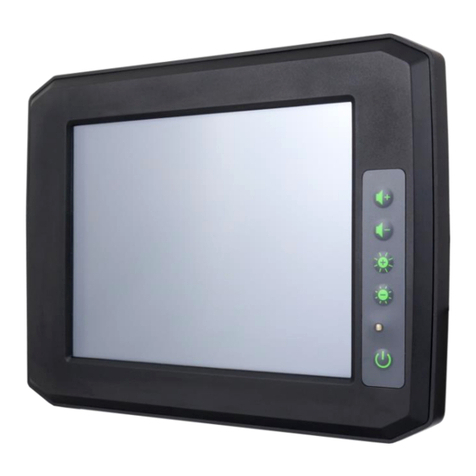
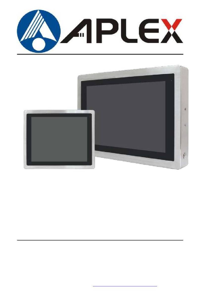
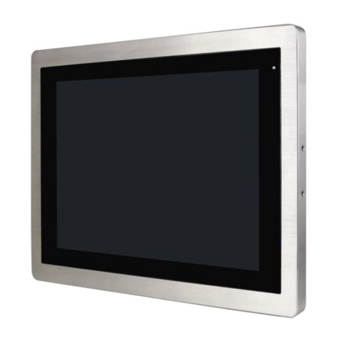
Aplex APC-3X97A User manual

APC-3X97Auser manual
1
APC-3X97A Panel PC
User Manual
Release Date Revision
Apr 2012 V1.0
® 2012 Aplex Technology, Inc. All Rights Reserved. Published in Taiwan
Aplex Technology, Inc.
15F-1, No.186, Jian Yi Road, Zhonghe District, New Taipei City 235, Taiwan

APC-3X97Auser manual
2
Warning!___________________________________
Safety & Warranty
1. Read these safety instructions carefully.
2. Keep this user's manual for later reference.
3. Disconnect this equipment from any outlet before cleaning. Do not use liquid or spray
detergents for cleaning. Use a damp cloth.
4. For pluggable equipment, the power outlet must be installed near the equipment and must be
easily accessible.
5. Keep this equipment away from humidity.
6. Put this equipment on a reliable surface during installation. Dropping it or letting it fall could
cause damage.
7. The openings on the enclosure are for air convection. Protect the equipment from overheating.
DO NOT COVER THE OPENINGS.
8. Make sure the voltage of the power source is correct before connecting the equipment to the
power outlet.
9. All cautions and warnings on the equipment should be noted.
10. If the equipment is not used for a long time, disconnect it from the power source to avoid
damage by transient over-voltage.
11. Never pour any liquid into an opening. This could cause fire or electrical shock.
12. NEVER OPEN THE EQUIPMENT. FOR SAFETY REASONS, ONLY QUALIFIED SERVICE
PERSONNEL SHOULD OPEN THE EQUIPMENT.
13. If any of the following situations arises, get the equipment checked by service personnel:
�The power cord or plug is damaged.
�Liquid has penetrated into the equipment.
�The equipment has been exposed to moisture.
�The equipment does not work well, or you cannot get it to work according to the users manual.
�The equipment has been dropped and damaged.
�The equipment has obvious signs of breakage.
14. DO NOT LEAVE THIS EQUIPMENT IN AN ENVIRONMENT WHERE THE STORAGE
TEMPERATURE IS BELOW -20°C OR ABOVE 70°C. IT MAY DAMAGE THE EQUIPMENT.
APC-3X97Auser manual
3
This equipment generates uses and can radiate radio frequency energy and if not installed and
used in accordance with the instructions manual, it may cause interference to radio
communications.
It has been tested and found to comply with the limits for a Class A computing device pursuant to
FCC Rules, which are designed to provide reasonable protection against such interference when
operated in a commercial environment. Operation of this equipment in a residential area is likely
to cause interference in which case the user at his own expense will be required to take whatever
measures may be required to correct the interference.
Disclaimer
This information in this document is subject to change without notice. In no event shall Aplex Technology
Inc. be liable for damages of any kind, whether incidental or consequential, arising from either the use or
misuse of information in this document or in any related materials.
Electric Shock Hazard –Do not operate the machine with its back cover removed. There are
dangerous high voltages inside.

APC-3X97Auser manual
4
Table of Contents______________________
Warning!…………………………………………………………………………….……..….2
Disclaimer………………………………………………………………….…………………2
Chapter 1 Getting Started
1.1 Features…......…………….……………………………………..…..…...…6
1.2 Specifications………………………………………….………………...…..6
1.3 Brief Description ……………………………...……………………………8
1.4 Chassis Dimensions..…………………………………………………..…..9
Chapter 2 Mainboard
2.1 Mainboard Specifications….……………………….………………...........12
2.2 Onboard Jumpers and Port Pinouts……….……………….…….…….......18
Chapter 3 AMI BIOS Setup
3.1 Operations after POST Screen................................................27
3.2 Standard CMOS Features..............................................28
3.3 Advanced BIOS Features.....................................................31
3.4 Advanced Chipset Features Setup............................... 34
3.5 Integrated Peripherals................................................................... 37
3.6 Power Managements Setup................................................. 42
3.7 PnP/PCI Configurations Setup...................................................... 45
3.8 PC Health Status…................................................................ 47
3.9 Load Fail-Safe/Optimized Defaults.............................................. 48
3.10 Set Administrator/User Password....................................... 50
3.11 Save & Exit Setup……………............................................. 50
3.12 Exit Without Saving…………………………………….……………………. 51
Chapter 4
4.1 SuperIO Model.................................................................................................52

APC-3X97Auser manual
5
4.2 W83627UHG Access index port...................................................52
4.3 Configure GPIO register sequence................................................................52
4.4 Read/write GPIO sequence………………………………………………….......52
4.5 Software programming example....................................................................52
Chapter 5
5 Watchdog Source Code...................................................................................59
Chapter 6 Installation of Drivers
6.1 Intel Chipset Drivers .....……………….……………………………….63
6.2 Intel Graphics Media Accelerator Driver……..……………………….66
6.3 RealTek Gigabit LAN Driver………………………………………….70
6.4 Realtek HD Driver Installations…………………………………… 73
Chapter 7 Touch Driver Installation
7.1 Windows 2000/XP Driver Installation for Controller Board.……….….76
7.2 Configuring PenMount Windows 2000/XP Driver……………………..76
Figures
Figure 1.1: Front View ………………….……………………………..…………8
Figure 1.2: Rear View…………...…………………………………………………8
Figure 1.3: Dimensions of the APC-3597A ...........…………………………………9
Figure 1.4: Dimensions of the APC-3797A ………………………… ………..…10
Figure 1.5: Dimensions of the APC-3997A.........................................................11
Figure 2.1: Mainboard Overview….………………..….……………………..……..12
Figure 2.2: Mainboard Dimensions…………………………………………………13
Figure 2.3: Connector and Jumper Locations……………………………………15
Figure 7.1: Bird’s Eye View of Control Board....................................................76

APC-3X97Auser manual
6
Chapter 1_____________________________
1.1 Features
Fanless Design
Intel Atom N270 1.6GHz Processor, FSB 533MHz
One 200 Pin SO-DIMM socket, up to 2GB DDR2 533MHz SDRAM
11~32V DC wide range power input
Total NEMA4/IP65 compliant
Sealed 5-Wire Resistive Touch Screen, Optional for GFG Resistive Touch Screen
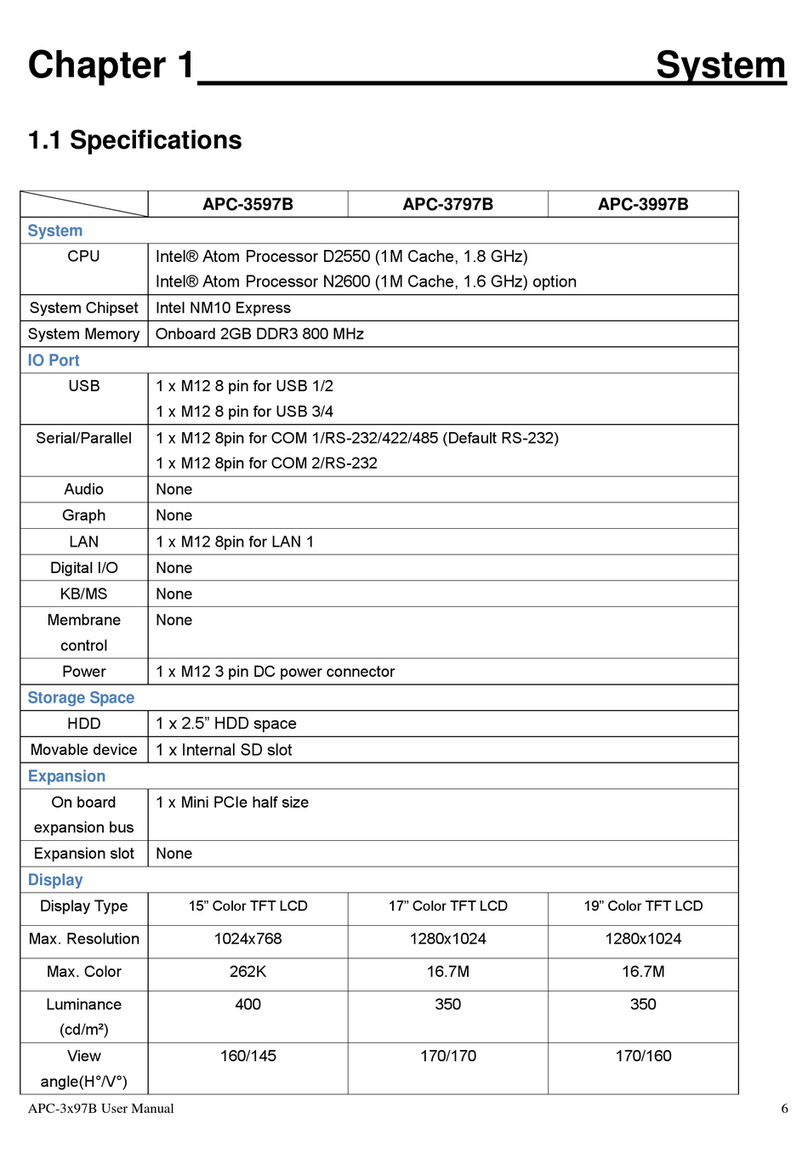
1.2 Specifications
System
System
Processor
Intel Atom Processor N270 1.6GHz built-in, FSB533MHz
System Memory
1 x 200-pin SO-DIMM socket, support 533MHz up to 2GB SDRAM
System Chipset
Intel 945GSE + Intel ICH7M
External I/O Port
Standard I/O:
2 x USB 2.0 connectors
1 x RJ-45 LAN connector
1 x DB-9 RS-232 (COM 1) connector
1 x DB-9 RS-232/422/485 connector (COM 2), Default RS-232
1 x DC Power input
Full Function I/O:
1 x VGA DB-15 port
1 x Audio Line-out port
Solid Storage Disk
1 x CF Slot (internal)
1 x 2.5” HDD bay for SATA HDD
OS Support
Windows XP Professional, XP Embedded
LCD
Display Type
TFT-LCD
Max. Resolution
15”1024x768 (APC-3597A)
17”/19”1280x1024 (APC-3797A/3997A)
Max. Color
262K
Luminance (cd/m2)
350 (cd/m2)(APC-3597A)
300 (cd/m2)(APC-3797A/3997A)
ViewAngle
H:120°/ V:100°(APC-3597A)
H:160°/ V:170°(APC-3797A)

APC-3X97Auser manual
7
H:160°/ V:160°(APC-3997A)
Backlight Lifetime
50,000hrs
Touch Screen
Type
Resistive Type
Light Transmission
80%
Power Supply
Power Input
DC 11~32V
Mechanical
Construction
Stainless Steel
IP Rating
Total IP65
Mounting
VESA 75x75 (APC-3597A/3797A)
VESA 100x100 (APC-3997A)
Dimension
399 (W) x324(H) x 53 (D) mm (APC-3597A)
432 (W) x358(H) x 57 (D) mm (APC-3797A)
470 (W) x389(H) x 60 (D) mm (APC-3997A)
Environmental
Operating Temperature
0~50 ゚C
Storage Temperature
-20~60 ゚C
Storage Humidity
10~90% @40℃non-condensing
Certificate
Meet CE/FCC Class A

APC-3X97Auser manual
8
1.3 Brief Description of the APC-3X97A
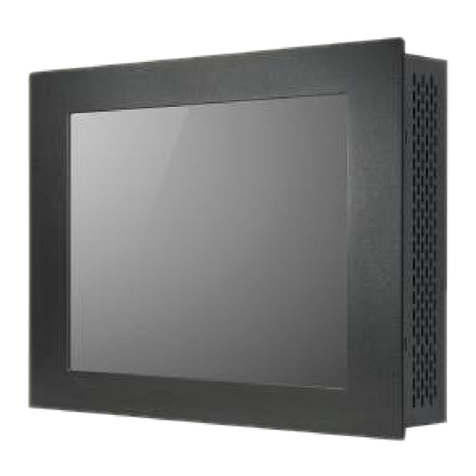
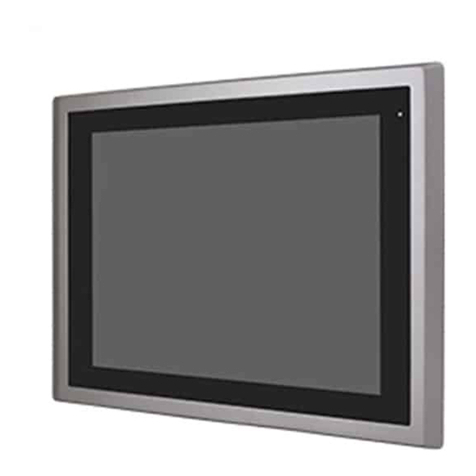
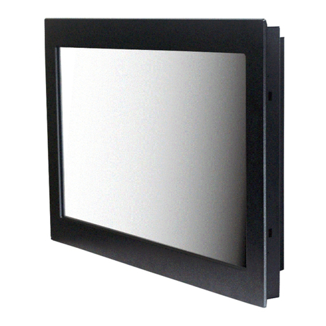
The chassis of theAPC-3X97A is made of stainless steel with an ultra slim profile. It is built in the Intel
Atom N270 1.6GHz, FSB 533MHz, it is fanless. The model comes with a 15”~19”inch TFT LCD
display, total NEMA 4/IP65 compliant, space for one 2.5-inch HDD, resistive touch screen, a DC
11~32V wide range power input. This industrial panel PC also features 2 COM ports, 2 USB ports and
1 x Gigabit LAN port. It is ideal for use as a PC-based controller for Automotive, Logistic Process,
Materials Handling, and Kiosk applications.
Figure 1.1: Front View of APC-3997A
Figure 1.2: Rear View of APC-3997A

APC-3X97Auser manual
9
1.4 Chassis Dimensions
Figure 1.3: Dimensions of the APC-3597A

APC-3X97Auser manual
10
Figure 1.4 Dimensions of the APC-3797A

APC-3X97Auser manual
11
Figure 1.5 Dimensions of the APC-3997A

APC-3X97Auser manual
12
Chapter 2_____________________________
2.1 Mainboard Specifications
Figure 2.1: Mainboard Overview

APC-3X97Auser manual
13
Figure 2.2: Mainboard Dimensions

APC-3X97Auser manual
14

APC-3X97Auser manual
15
Figure 2.3: Connector and Jumper Locations

APC-3X97Auser manual
16
Specifications
Board Size
165 x 115mm
CPU Support
Intel Atom N270 1.6 GHz with 533MHz FSB
Chipset
Intel 945GSE + Intel ICH7M
Memory Support
1x200pin 533/400MHz DDR2 SO-DIMM support, up to 2GB
SDRAM
Graphics
Intel Graphics Media Accelerator 950VGA integrated in Intel
945GSE
18-bit dual-channel LVDS integrated in Intel 945GSE
18/24 bit dual-channel LVDS support by Chrontel CH7308B
1 x DB15 Female connector for external
Super I/O
Winbond W83627UHG
BIOS
Award BIOS
Storage
2 x SATA Connector
1 x Compact Flash II Slot
1 x 44-pin IDE Connector
Network
2 x Gigabit Ethernet Port by RJ45 with LED indicators -
Ethernet controller :
2 x PCIe by one bus Realtek 8111D
USB
4 x USB 2.0 stack port for external
2 x USB 2.0 header for internal
Serial
1 x RS232 port, DB9 connector for external (COM1),
pin 9 w/5V/12V/Ring select
1 x RS232/422/485 select header for internal (COM2),
default RS232
4 x RS232 header for internal (COM3 –COM6)
Digital I/O
8-bit digital I/O by header
4-bit digital Input
4-bit digital Output
Battery
Support CR2477 battery by 2-pin header
Audio
Support Audio via Realtek ALC662 HD audio decoder
Support Line-in, Line-out, MIC by 2x5-pin header
Printer
1x LPT port by 2x13-pin header
Keyboard
/Mouse
1x PS2 keyboard/mouse by 1x6 -pin wafer connector
Expansion Bus
1x PC 104+ connector (PCI master 4, jumper for +3.3V &

APC-3X97Auser manual
17
5V select)
1x PCIe ( PCI-e 1x +SMBUS+USB2. 0 ) mini card
Power
Management
DC12V input
1 x 2x2-pin power input connector
Front I/O
by 2x5-pin header
Power on/off switch
Reset switch
Power LED status
HDD LED status
Buzzer
Watchdog Timer
Software programmable 1 –255 second by Super I/O
External I/O port
1 x COM Port (COM1)
4 x USB 2.0 Ports (stack)
2 x RJ45 GbE Port (10/100/1000Mbps)
1 x VGA Port
Temperature
Operating: 0 –60 degree C
Storage: -20 –80 degree C
Humidity
5% - 95%, non-condensing, operating
EMI/EMS
CE/FCC class A

APC-3X97Auser manual
18
2.2 Onboard Jumpers and Port Pinouts
1. JVCCIO (2.0MM 1X3) PCI-104 port voltage selection jumper: select voltage for PCI-104+ device
JVCCIO
PCI-104 VCCIO
Voltage
CLOSE
1-2
+3.3V (default)
CLOSE
2-3
+5V
2. JCLR_CMOS (2.0MM 1X3) CMOS clear jumper: CMOS clear operation will permanently reset old
BIOS settings to factory defaults.
JCLR_CMOS
CMOS
CLOSE 1-2
NORMAL
(default)
CLOSE 2-3
CLEAR CMOS
Procedures of CMOS clear:
1. Turn off the system and unplug the power cord from the power outlet;
2. To clear the CMOS settings, use the jumper cap to close pins 2 and 3 for about 3 seconds then
reinstall the jumper clip back to pins 1 and 2.
3. Power on the system again;
4. When entering the POST screen, press the <DEL> key to enter CMOS Setup Utility to load optimal
defaults;
5. After the above operations, save changes and exit BIOS Setup.
3. BAT (1.25.0MM 1X2) Ext. Battery port: a 3.3V battery is embedded to provide power for CMOS.
PIN#
Signal
Name
PIN1
VBAT
PIN2
Ground
4.COM2-COM6 (2.0MM 2X5)COM2~COM6 port: up to 5 standard RS232 ports are provided. They
can be used directly via COM adapter cable connection.
Signal
Name
Pin#
Pin#
Signal
Name
DCD
1
2
RXD
TXD
3
4
DTR
Ground
5
6
DSR
RTS
7
8
CTS
RI
9
10
NC

APC-3X97Auser manual
19
Note: COM2 port is controlled by pins No.8~10 of JCOM. For details, please refer to
description of JCOM.
5.KB/MS (2.0MM 1X6) PS/2 keyboard/mouse port: the port can be connected to PS/2 keyboard or
mouse via a dedicated adapter cable for direct use.
Pin#
Signal
Name
1
KBDATA
2
MSDATA
3
Ground
4
+5V
5
KBCLK
6
MSCLK
6. LPT (2.0MM 2X13)Parallel port: a standard 26 pin parallel port is provided to connect parallel
peripherals as required.
Signal Name
Pin#
Pin#
Signal Name
PSTB#
1
2
PD0
PD1
3
4
DP2
DP3
5
6
DP4
DP5
7
8
DP6
DP7
9
10
ACK#
BUSY
11
12
PE
SLCT
13
14
AFD#
ERR#
15
16
INIT#
SLIN#
17
18
Ground
Ground
19
20
Ground
Ground
21
22
Ground
Ground
23
24
Ground
Ground
25
26
Ground
7. GPIO (2.0MM 2X5) General-purpose input/output port: it provides a group of self-programming
interfaces to customers for flexible use.
Signal Name
Pin#
Pin#
Signal Name
GPIO20
1
2
GPIO60
GPIO21
3
4
GPIO61
GPIO22
5
6
GPIO62
GPIO23
7
8
GPIO63
Ground
9
10
+5V

APC-3X97Auser manual
20
8. COM22 (2.0MM 2X5): it provides selectable RS422/485 serial signal output.
Signal Name
Pin#
Pin#
Signal Name
A
1
2
Terminal
Resistance
B
3
4
Terminal
Resistance
Z
5
6
NC
Y
7
8
NC
Ground
9
10
NC
9. USB4 (2.0MM 2X5) Front USB connector: it provides two USB ports via a dedicated USB
adapter cable.
Signal Name
Pin#
Pin#
Signal Name
+5V
1
2
+5V
USB_P6_DN
3
4
USB_P7_DN
USB_P6_DP
5
6
USB_P7_DP
Ground
7
8
Ground
NC
9
10
Ground
Note:
Before connection, make sure that pinout of the USB adapter is in accordance with that of the said
tables.Any inconformity may cause system down and even hardware damages.
10. JCOM (2.0MM 2X6) COM1/2 setup jumper: pin 1~6 are used to select signal out of pin 9 of
COM1 port; pin 7~12 are used to select output type for COM2 port (RS232 or RS422/485).
JCOM
Function
CLOSE 1-2
COM1 Pin9=RI (default)
CLOSE 3-4
COM1 Pin9=+5V
CLOSE 5-6
COM1 Pin9=+12V
CLOSE 7-9
CLOSE 8-10
COM2 FOR RS232 FROM COM2
(default)
CLOSE 9-11
CLOSE 10-12
COM2 FOR RS485/RS422 FROM
COM22
Note:
1. As determined by its hardware design, the board features full-duplex RS485 communication. Like
RS422, a four-wire connection is necessary.
2. Since COM2 and COM22 use the same address, they cannot work at the same time.
Table of contents
Other Aplex Touch Panel manuals

Aplex
Aplex APC-3x93P_3X93R User manual

Aplex
Aplex ARCDIS-112APR(H) User manual

Aplex
Aplex ARCHMI-7XX User manual

Aplex
Aplex APC-3XX2 series User manual

Aplex
Aplex APC-3X15B User manual

Aplex
Aplex APC-3X19A User manual

Aplex
Aplex ViTAM-924A User manual

Aplex
Aplex APC-3296P User manual

Aplex
Aplex ARCHMI-8 H Series User manual

Aplex
Aplex APC-3x84A User manual

Aplex
Aplex APC-3228 User manual

Aplex
Aplex AHM-6077 User manual

Aplex
Aplex AEx-P526 User manual

Aplex
Aplex APC-3x84B User manual

Aplex
Aplex ARCHMI-807 User manual

Aplex
Aplex VITAM-9 A Series User manual

Aplex
Aplex ViTAM-610PH User manual

Aplex
Aplex APC-3X17B User manual

Aplex
Aplex APC-3284A User manual

Aplex
Aplex APC-3*94P/R series User manual