Ziton ZP755BV-4 Assembly instructions

© 2014 UTC Fire & Security. All rights reserved. 1 / 4 P/N 501-1789ZE-1-10 • REV 10 • ISS 16APR14
ZP755BV-4 Addressable Base Sounder with
Visual Indicator Installation Sheet
Description
The ZP755BV-4 is an addressable base sounder with visual
indicator, designed for use in Ziton analogue addressable fire
detection and alarm systems.
Note: The visual indicator of this product does not comply with
EN 54-23 and must not be used in fire alarm installations
where fire notification beacons are required.
The sounder includes a volume control, an address-setting
switch, programmable tone settings, and a pair of jumpers to
select the operating power — from the analogue addressable
loop or an external supply. The device plugs into a base that is
purchased separately. See Table 1 for a list of model numbers.
Table 1: Models
Number Description
Sounder,
ZP755BV-4P
Base sounder/Visual indicator, Polar white
Cover,
ZP755-COV-P
ZP755-COV-R
Cover for ZP755B Base sounder
with no detector, Polar white
Cover for ZP755B Base sounder
with no detector, Red
Base,
SPB–2P
Base, Polar white
Installation
To install the device:
1. Wire the base
2. Set the operating power
3. Set the address
4. Set the operating mode
5. Set the tone
6. Set the volume
7. Mount the sounder onto the base
The details of each step are given below
Wiring the base
Connect the loop wiring for the base as shown in Figure 1.
There is no wiring between the sounder and base.
Figure 1: Loop wiring for the base
1. Ext. 24 VDC+ IN/OUT
4. Ext. 24 VDC ground IN/OUT
5. Loop+ IN/OUT
7. Shield
8. Loop − IN/OUT
Setting the operating power
The sounder includes a pair of power selection jumpers, J1
and J2. To select the source of the sounder operating power,
position the jumpers as shown in Figure 2.
8
4
5
1

2 / 4 P/N 501-1789ZE-1-10 • REV 10 • ISS 16APR14
Figure 2: Power-selection jumper configuration
1. Loop powered 2. External 24 VDC
Note: When using an external power supply, use only one that
is CE and EN 54-4 compliant to power all the sounders on the
same loop. Ensure connection to number 1 and number 4 in
addition to the loop wiring number 5 and number 8.
Setting the address
The sounder includes a seven-segment DIP switch (SW1) for
assigning device addresses. Each switch segment has a
decimal value as shown in Figure 3. The address is the sum of
all the switch segments in the ON position. The switch is used
to set the device address in binary code. The switch may be
set to represent any address from 1 to 127.
For example, to select a device address of 007, set SW1-1,
SW1-2, and SW1-3 to the ON position and the remaining
switch segments to the OFF position.
Figure 3: Address switch setting
Mode, tone, and volume settings
The sounder includes a seven-segment DIP switch (SW2) to
select the operating mode, tone, and volume. See Figure 4.
Figure 4: Mode of Operation switch settings
1. Power selection jumpers
2. SW2 configuration switch
3. Tone
4. Addressing mode
5 Visual indicator operating
mode
6. Volume
Setting the addressing mode
Configure the base sounder to operate with or without a
detector at the same address as shown in Table 2.
Table 2: Setting address mode
Switch Setting
SW2-4 OFF The sounder is stand-alone with a unique
loop address not used by another detector.
SW2-4 ON The sounder shares the address with a
detector to expand the number of devices
supported by the loop.
Configure the base sounder to enable or disable the visual
indicator as shown in Table 3.
Table 3: Setting Visual Indicator operating mode
Switch Setting
SW2-5 ON Enable the
visual indicator.
SW2-5 OFF Disable the
visual indicator. Not recommended with
Silent tone.
Setting the volume
Use SW2-6 and SW2-7 to set the volume. Level 1 is the lowest
volume setting, and level 4 is the highest as shown in Table 4.
Refer also to the measured anechoic sound levels in Figure 7.
Table 4: Volume settings
00 – Level 1 10 – Level 2 01 – Level 3 11 – Level 4
Average dBA measurement
3 dBA less than
level 2. 3 dBA less
than level 3. 3 dBA less
than level 4. Certified tones
[1].
[1] UK-continuous, UK intermittent, UK two-tone are EN 54-3
compliant.
Setting the tone
The control panel can operate the sounder in two different pre-
programmed tones, by selecting SW2-1, SW2-2, and SW2-3.
Refer to Table 5 Tone settings.
Note: Two additional tones are available, the Class change
and the Visual indicator only tone. However, these tones may
not be available for legacy control panels. Please refer to the
configuration options of your control panel to confirm tone
availability.
J1 J1J2 J2
21
1
2
3 6
45

P/N 501-1789ZE-1-10 • REV 10 • ISS 16APR14 3 / 4
Table 5: Tone settings
Device mode SW2 switch setting -1-2-3 Primary warning Secondary evacuation Attention (nonfire)
ZP755 0 UK intermittent UK continuous Class change
ZP755 1 UK continuous UK two-tone Class change
ZP755 2 UK two-tone UK intermittent Class change
ZP755 3 Australian whoop Australian alert Class change
ZP755 4 Swedish tone Dutch slow whoop Class change
ZP755 5 ISO8201 French two-tone Class change
ZP755 6 German Visual indicator only Class change
ZP754 7 UK intermittent UK continuous Class change
Table 6: Tones
Tone name Description Freq (Hz) Cycle time
UK continuous
[1] Continuous
(UK) 980 Continuous
UK intermittent
[1] Intermittent fast
0.5 s (UK) 980 1s (1 Hz) 0.5 s on, 0.5
s off
UK two-tone
[1] Two-tone (UK) 980
670 0.5 s tone 1
0.5 s tone 2
Australian
whoop Australian slow
whoop
ascending
500 to
980 4 s
Australian alert
[2] Australian alert
ISO7731 440 0.55 s on, 0.55 s off ±
10%
Swedish tone Swedish fast
pulse 670 0.33 – 0.55 s
(3-4 Hz)
Pulse ratio
>0.35 < 0.7
Dutch slow
whoop Dutch slow
whoop
ascending
500 to
1200 4s
3.5 s on 0.5 s off
ISO8201 Temporal
ISO8201
3 pulse and
wait
980 4 s
0.5 s on/0.5 s off
1.5 s wait
French two
tone French two-
tone 554
440 90-110ms
380-420ms
= 500 ms ± 5%
German German fast
whoop
descending
1200 to
500 1 s
no “off”
Class
Change 3 tones and
wait 1000,
1200,
1500
4s
Visual Indicator
only Silent and
visual indicator
only
[1] The tones UK-continuous, UK-intermittent, and UK-two-tone are EN
54-3 compliant.
[2] ISO7731.
Figure 5: Mounting
1. Base
2. Release aid (3X) 3. Release/lock catch
4. Addressable sounder
Mounting the sounder
Align the addressable sounder to the base. Push up (A) and
turn the sounder until it clicks into place (B). Push the sounder
up once more to engage (C). Refer to Figure 5.
To remove the sounder from the base, the three release aid
tabs must be depressed, and then the sounder can be
detached.
4
3
2
1
A
B
C

4 / 4 P/N 501-1789ZE-1-10 • REV 10 • ISS 16APR14
Sounders per loop
The sounder can be powered directly from the loop of Ziton control
panels. Use Table 5 Tone settings, in conjunction with Figure 6, to
determine the quantity of detectors and sounders that can be
connected to a two-core shielded loop when loop powered.
Figure 6: Detector/sounders per loop
A. Cable length panel to first sounder
B. Cable length first to last sounder
C. Cable length last sounder to panel
1. Detectors and Sounders
Table 7: Maximum detectors and sounders per loop
A B C Quantity allowed [1]
10 m 980 m 10 m 60 detectors and 35 sounders
90 detectors and 30 sounders
100 m 800 m 100 m 50 detectors and 35 sounders
90 detectors and 30 sounders
200 m 600 m 200 m 40 detectors and 35 sounders
90 detectors and 30 sounders
300 m 400 m 300 m 40 detectors and 30 sounders
90 detectors and 25 sounders
[1] Using a two-core shielded loop of 1000 meters cable size 1.5 mm²
Specifications
Operating voltage
External supply
Loop supply, ZP protocol
18 to 30 VDC
19.5 to 20.5 V pulsed, max. 4 V line loss
Current (line powered)
Quiescent (RMS)
Alarm (RMS)
Alarm (excluding device
address)
Alarm (at device address)
500 µA
6 mA
14 mA max.
14 mA max.
Current (externally powered)
Quiescent (RMS)
Alarm (RMS)
Maximum number
470 µA
500 µA
35 per 1 km loop (subject to cable size and
sounder spacing)
Strobe
Frequency
Light output
Flash rate 1.1 seconds
Less than 1J xenon element
Tones See Table 5 Tone settings.
See Table 6 Tones.
Sound distribution Wide
Measured anechoic sound levels See Figure 7
Monitoring
Operating power level
Sound output level
Tested continuously
Self test facility
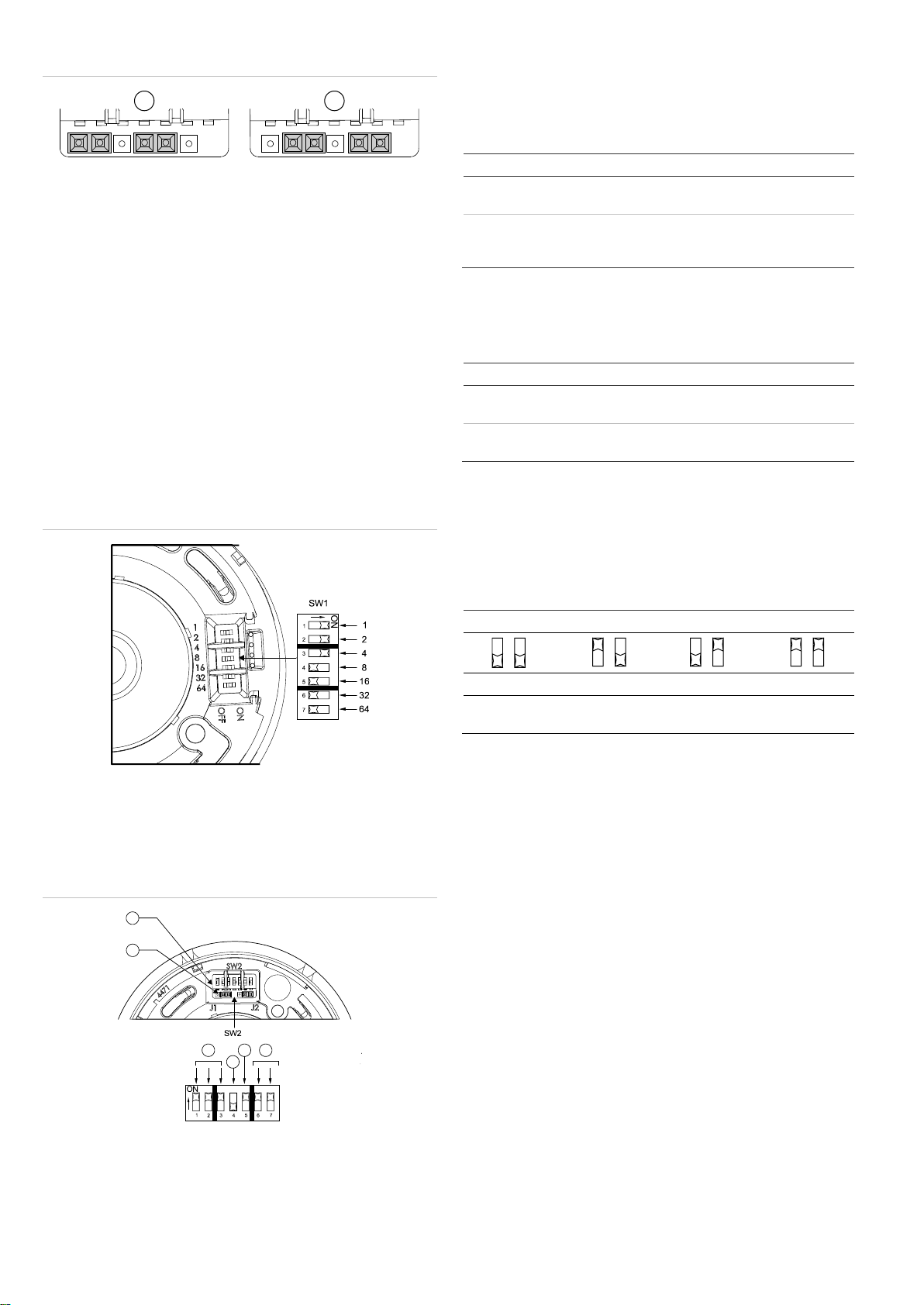
Compatibility Ziton analogue addressable systems
Addressing method 7-segment DIP switch
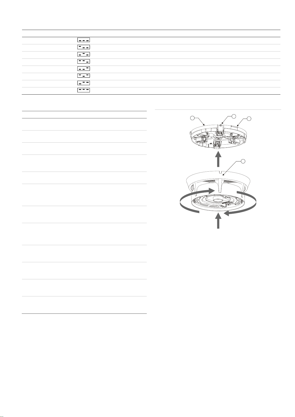
Mounting Surface, with base
Wiring Two-core loop
Construction
Material
Weight
Dimensions (Ø × D)
Moulded thermoplastic
156 g
127 × 47 mm incl. base
Operating environment
Temperature
Relative humidity
−10 to +60°C
10 to 95%, noncondensing
Storage temperature −20 to +70°C
Figure 7: Measured anechoic sound levels
Note: These measurements correspond to the highest level for the EN 54-
3 compliant tones of UK-continuous, UK intermittent, and UK-two-tone.
Regulatory information
This section includes both regulatory information and a summary on
the declared performance according to the Construction Products
Regulation 305/2011. For detailed information refer to the product
Declaration of Performance.
Certification
Certification body 0370
Declaration of
Performance number 360-5202-0199
Year of first CE
marking 14
Product Identification ZP755BV-4P
Intended use See DoP point 3
Essential
characteristics See DoP point 9
Manufacturer Gulf Security Technology Co.,Ltd
80, Changjiang East Road,
QETDZ, Qinhuangdao, Hebei Province, China 066004
Authorized EU manufacturing representative:
UTC Fire & Security B.V.
Kelvinstraat 7, 6003 DH Weert, Netherlands
European Union
directives 1999/5/EC (R&TTE directive): Hereby, UTC Fire &
Security declares that this device is in compliance with
the essential requirements and other relevant provisions
of Directive 1999/5/EC.
2002/96/EC (WEEE directive): Products marked with this
symbol cannot be disposed of as unsorted municipal
waste in the European Union. For proper recycling,
return this product to your local supplier upon the
purchase of equivalent new equipment, or dispose of it
at designated collection points. For more information
see: www.recyclethis.info.
Contact information
For contact information, see www.utcfssecurityproducts.eu.
165
O
105
O
75
O
45
O
15
O
135
O
dBA 65 70 75 80 856570758085
Other Ziton Marine Equipment manuals