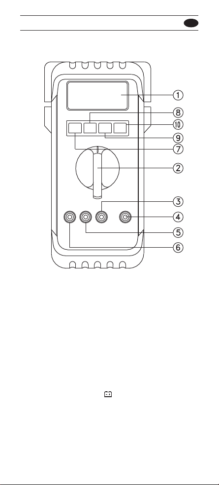
1-2 Front Panel
Refer to Figure 1 and the following numbered steps to
familiarize yourself with the meter's front panel controls
and connectors.
1. Digital Display — The digital display has a 3200
counts LCD readout with 65 segments analog bar
graph, auto polarity, decimal point, , HOLD, DC ,
AC , ,RANGE, and Unit annunciators.
2. Rotary Switch — Selects the desired function and
range.
3. COM Input Terminal — Ground input connector.
4. V Ω Input Terminal — Positive input connector for
Volts, Ohms and Diode measurements.
5. μA mA Input Terminal — Positive input connector for
current and measurements. (up to 300mA).
6. A Input Terminal — Positive input connector for current
measurements, up to 10A.
7. Function Switch (Blue) — Press the switch to
measure AC voltage or DC voltage in the Voltage mode
or to measure AC current or DC current in the current
mode, or to measure continuity or diode check in /
mode.
8. Reset Switch — The meter can be turned back on by
pushing "RESET" key switch.
9. Hold Switch — This switch is used to hold measured
values for all functions. When pressed the "HOLD"
annunciator is displayed. Conversions are made but the
display is not updated.
10. Range Switch (Manual Range) — The "Range"
switch is pressed to select manual ranging and to
change ranges. When the "Range" switch is pressed
once, the "RANGE" annunciator on the LCD
disappears. Press the "Range" switch to select the
appropriate range to be used. Press the "Range" switch
and hold for 2 seconds to return to Auto-ranging.
67 EN