APPA 97 User manual

-
-
-
DIGITAL MULTIMETER
C
E
OPERATOR'S MANUAL
APPA 97 197R

A
WARNING
THESE SERVICING INSTRUCTIONS ARE FOR USE BY QUALIFIED PERSONNEL ONLY.
TO AVOID ELECTRIC SHOCK, DO NOT PERFORM ANY SERVICING OTHER THAN THAT
CONTAINED IN THE OPERATING INSTRUCTIONS UNLESS YOU ARE QUALIFIED TO DO SO.
Also
the complete duty cycle for the
20A
measurement should be stated as on for
30
seconds rnax.,
and off for
3
minutes rnin.

INTRODUCTION
1-1
Unpacking and Inspection
Upon removing your new Digital Multimeterfrom its packing, you should have the following items:
1.
Digital Multimeter.
2.
Test lead set (one black, one red).
3.
Operators manual.
4. Protective holster.
1-2
Meter Safety
Terms as Marked on Equipment.
ATTENTION
-
Refer to manual.
DOUBLE INSULATION
-
Protection Class
11.
DANGER
-
Risk of electric shock.

Symbols in this Manual.
This symbol indicates where cautionary or other information is found in the manual.
B-
FUSE
a
Battery
1-2 Front Panel
Refer to Figure
1
and to the following numbered steps to familiarize yourself with the meter's front panel controls
and connectors.
1.
Digital Display
-
The digital display has a 3400 counts LCD readout with
65
segments analog bar graph, auto
polarity, decimal point,
"a"
AC, LOR, RANGE, HOLD and unit annunciators
2.
Rotary Switch -Select the Function and Range desired.
3.
COM
lnput Terminal -Ground input connector.
4.
VR
*
lnput Terminal
-
Positive input connector for Volts, Ohms and Diode.
5.
FA
mAlnput Terminal
-
Positive input connector for Am? measurements (up to 320mA).
6.
A lnput Terminal
-
Positive input connector for Amp measurements (up to 20A).

7.
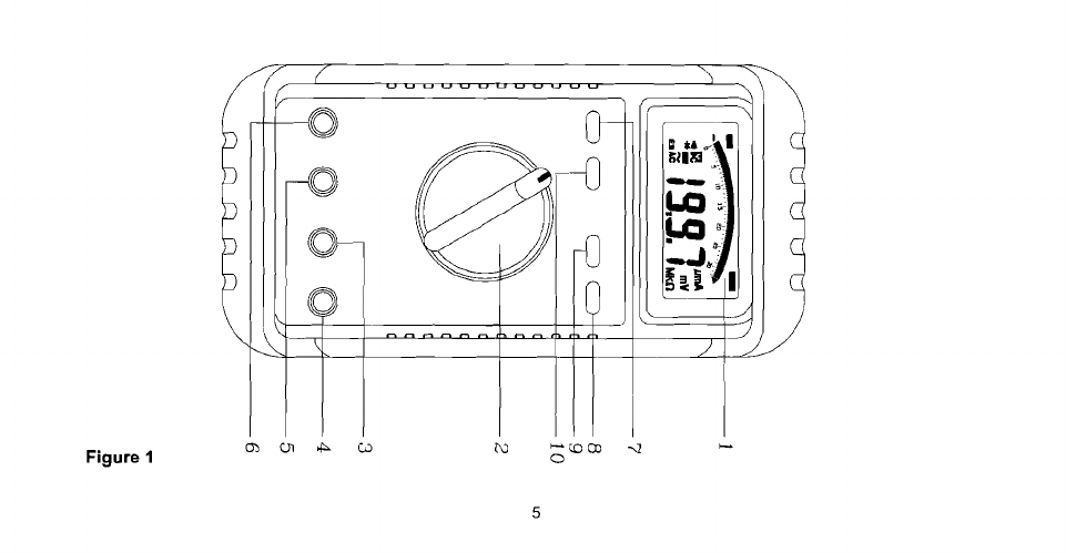
Range Switch, (Manual Range)
-"RangeM switch is pushed to select manual ranging and to change ranges.
When "Range" switch is pushed once "RANGE" anunciator on the LCD is
appeared. Push "RANGE" switch to select appropriate range to be used.
Push "RANGE" switch and hold
2
seconds to return to Autoranging.
8.
ACIDC,
-8
I
*
Selection Switch
-
Push the switch to measure AC Current or DC Current in the current
mode or to measure continuity or diode in
.$I
*
mode.
9.
Hold
Switch
-This switch is used to hold measured value for all functions, and then "HOLD" annunciator is
displayed. Conversions are made but the display is not updated.
10.
DELAY
Q
Switch
-This switch is used to delay hold the measured value. The "HOLD" annuciator is
displayed after push the "DELAY
Q"
switch about
6
seconds. Push "HOLD" switch to
cancel display hold or push "DISPLAY
Q"
switch after
6
seconds the display hold is
canceled. Conversions are made but the display is not updated.
The beep will sound when push the HOLD Switch or after about
6
seconds the beep
will sound when push the "DELAY
Q"
Switch.

Figure
1

SPECIFICATIONS
2-1
General Specifications
Display
:
The Liquid Crystal Display (LCD) with a maximum reading of 3200 and 65 segments bar graph.
Polarity lndication
:
Automatic, positive implied, negative indicated.
Overrange lndication
:
"OL"
or
"-OL".
Low Battery lndication
:
"a
'7sdisplayed when the battery voltage drops below operating voltage.
Sampling
:
2
timeslsec for digit. 12 timeslsec for analog bargraph.
Auto Power Off
:
Approx 10 minutes.
Operating Ambient
:
0°C to 50°C, 0 to 80% R.H.
Storage Temperature
:
-20°C to 60°C
,
0 to 80%
R.H.
when battery removed from meter.
Temperature Coefficient
:
0.15 x (Specified accuracy)
/
"C, <18"C or
>
28°C
.
Power Requirements
:
IEC LR03, AM4 or
AAA
size 1.5V x 2 (97)
6LF22,6AM6, or NEDA 1604A 9V x 1 (97R)
Battery Life
:
Alkaline 700 hours. (97)
Alkaline 350 hours. (97R)

Dimensions (W x
H
x
D)
:
84mm
x
175mm
x
31mm without holster.
95mm
x
192mm
x
50mm with holster.
Accessories
:
Protective Holster
,
battery (installed), operators manual.
2-2 Environmental Conditions
Indoor use.
Pollution Degree
:
2
Maximum Altitude
:
2000 Meter.
Installation Category
:
IEC 1010, 1000V Cat.
11,
600V Cat.m
CAT Application field
1
II
The circuits not connected to mains.
The circuits directly connected to Low-voltage installation.
IV
The building installation.
The source of the Low-voltage installation.

2-2
Electrical Specifications
Accuracy is
f
(%
reading
+
number
of
digits) at
23°C
f
5°C
at less than 80%
R.H
(1)
DC Volts
1
Range
1
Resolution Accuracy (97) Accuracy (97R) Over voltage
protection
1000V rms
Input Impedance
:
10MR

(2)
AC Volts
Range Resolution
1
Accuracy (97)
1
Accuracy (97R)
~
O~~~t~~~~~~e
1
,.*,
.
5dgt)
i
f
(I.3%rdg
+
3dgt)
**
OHz
1
1000V rrns
*
Frequency Response
:
40Hz
-
300Hz for 3V Range.
**
Frequency Response
:
40Hz
-
1KHz (40Hz
-
300Hz for 3V range).
AC Conversion Type
:
Average Sensing rrns indication. (97)
AC Conversions are ac-coupled, true rrns responding
,
calibrated to the rms value sine
wave input, the basic accuracy is for sine wave at full scale and non-sine wave below
half scale (3V Range just only for sine wave measurement) for non-sine wave accuracy
reference to
"*
. (97R)
Input Impedance
:
10MQ
/I
less than 100PF

"'Crest Factor
:
1.4 to 2 0, add 0.5% to Accuracy
2 0 to 2.5, add 2% to Accuracy
2.5 to 3.0, add 4% to Accuracy.
(3)
DC Current
Range
1
Reso=
1
Accuracy (97) Accuracy (97R)Ge
~urden
I
1
300pA 0.1 pV +_(l%rdg
+
2dgt) ?(l%rdg
+
2dgt) 200mV max.
I
3mA IpA t(l.2l;rdg
+
2dgt) (12%rdg+ 2
1
ZY
30mA 10pA +_(I %rdg
+
2dgt) *(I %rdg
+
2dgt) 200mV max.
.
--
-.
300mA O.lmA +_(I .2%rdg
+
2dgt) ?(I.2%rdg
+
2dgt) 2V max.
*
20A Range
:
30 seconds maximum above 10A input.
Overload Protection
:
1A (500V) fast blow fuse for pAmA input.
16A (500V) fast for A input.

(4)
AC Current
Frequency Response
:
40Hz
-
500Hz. (97)
40Hz
-
1KHz. (97R)
*
20A Range
:
30 seconds maximum above 10A.
Overload Protection
:
1A (500V) fast blow fuse for pArnA input.
16A (500V) fast for A input.
*AC Conversion Type
:
Average Sensing rrns indication. (97)
AC conversions are ac-coupled
,
true rrns responding, calibrated to the rrns value sine
wave input
,
the basic accuracy is for sine wave at full scale and non-sinewave below
half scale, for non-sine wave accuracy reference to"' (97R)
Range
300pA
3rnA
30rnA
300mA
Resolution
0
I
ljA
1PA
10pA
0 lrnA
--
20A
1
10rnA
Accuracy
(97)
Accuracy
*(97R)
I
Voltage Burden
1
200rnV rnax.
2V rnax
k(2 5%rdg
+
5dgt) +(2 5%rdg
+
5dgt)
2V rnax
200rnV rnax.
I
2V rnax
f(1 5%rdg
+
3dgt) +(I 5%rdg
+
3dgt)
+(2%rdg
+
3dgt) *(2%rdg
+
3dgt)

***
Crest Factor
:
1.4
to 2.0, add 0.5% to Accuracy.
2.0 to 2.5, add 2% to Accuracy.
2.5 to 3.0, add
4%
to Accuracy.
(5)
Resistance
RsngeRerolution
~
Accuracy (97) Accuracy (97R) Overload
Protection
Open circuit Voltage
:
1.3V
approx.

(6)
Diode Check and Continuity
*
for 0.4 to 0.8V
Range Resolution
Overload protection
:
6OOVrms max.
Accuracy Max.Test
Continuity
:
Built in-buzzer sound when resistance is less than 30R
Current
~
ciE%$!iZgd
I I
I
-
-
(7)
Auto Power Off
The meter will automatically shut itself off after approximately 10 minutes after power on
The meter can be turned back on by pushing "Power Reset" key switch.
(8)
Beep Guard
The beep will sound if the test lead is connected to the pAmA (10A) input terminal but the rotary function selector
is
not in the pAmA (10A) positions.

OPERATION
This instrument has been designed and tested in accordance with IEC Publication
1010,
Safety Require-
ments for Electronic Measuring Apparatus and has been supplied in a safe condition. This instruction
manual contains some information and warnings which have to be followed by the user to ensure safe
operation and to retain the instrument in safe condition.
3-1
Preparation and Caution before Measurement
1. Before measurement
,
warm up for at least 60 seconds.
2.
When the rotary function selector is changed during measurement
,
be sure do so only after removing the test
leads from the equipment.
3.
If the equipment is used near noise generating equipment
,
be aware that display may become unstable or
indicate large errors.
4.
Maximum rated voltage to earth for voltage and current measurements terminals is 1000V
AC
1
DC CAT.
II
.

3-2
Voltage Measurements
1. Connect the red test lead to the "VR+t
"
input terminal and the other (black) test lead to the "COM" terminal.
2.
Set the rotary function to the ACV or DCV position.
3. Connect the test leads to the device to be measured.
a
WARNING
:
TO AVOID ELECTRICAL SHOCK, HAZARD OR DAMAGE TO METER, DO NOT A ATTEMPT
TO MEASURE VOLTAGE THAT MIGHT EXCEED 1000 VOLT DC OR 750 VOLT AC
.
DO NOT
APPLY MORE THAN 1000V DC OR AC RMS BETWEEN THE COMMON INPUT TERMINAL
AND EARTH GROUND.
NOTICE
:
UNSTABLE DISPLAY MAY OCCUR ESPECIALLY AT 300mV RANGE, EVEN THOUGH YOU DON'T
PUT TESTED LEADS INTO INPUT TERMINALS. IN THIS CASE,
IF
AN ERRONEOUS READING IS
SUSPECTED, SHORT THE "VR+t
"
TERMINAL AND THE "COM" TERMINAL, AND MAKE SURE
THE ZERO DISPLAY.

3-3
Current Measurement
1.
Connect the red test lead to "vAmA terminal and the other (black) test lead to TOM" terminal, or use the
"A"
and "COM" terminal in the 20A range.
2.
Set function selector rotary switch to "FAor "mA or
"A".
3.
Measurement of AC current can be performed by pushing the "ACIDC" switch.
4.
Connect the test leads to the circuit to be measured.
3-4
Resistance Measurement
1.
Connect the red test lead to the
"VRU
"
terminal and the other (black) test lead to the "COM" terminal
2.
Set the rotary function selector to
"R"
position to measure the resistance
3.
For correct reading
,
ensure that the device being tested contains no voltage.
4.
Connect the test leads across the resistor to be measured. In order to ensure the best accuracy in measure-
ment of low resistance, short the test leads before measurement and memory the test probe resistance in mind.
This necessary to subtract for the resistance of the test leads themselves.

3-5
Continuity Check by Buzzer
1.
Connect the red test lead to the
"VR+t
"
terminal and the other (black) test lead to the "COM" terminal.
2.
Set the rotary function selector to
"+t
-$"
position.
3.
Connect the test leads to the circuit to be measureu
.
The b:,zzer will sound if the resistance of the circuit
measured is lower than
30R.
3-6
Diode Check
1.
Set the rotary switch at
"+t
-$
"
position.
2.
Connect black test lead to "COM" terminal and red lead to
"Vn+t
"
input terminal.
3.
Connect test leads to the diode normally the forward voltage drop of good silicon diode is shown between
400V
to
900V.
If the diode under test is defective
."000
(short circuit) or "OL" (non-conductance) is displayed.
Reverse check of diode if the diode under test is defective
"000"
or other value are to be displayed.

MAINTENANCE
a
WARNING
:
TO AVOID ELECTRICAL SHOCK REMOVE TEST LEAD BEFORE OPENING THE COVER.
4-1
General Maintenance
1.
Repairs or servicing not converted in this manual should only be performed by qualified personal.
2.
Periodically wipe the case with a dry cloth and detergent do not use abrasives or solvents.
4-2
Battery Installation or Replacement
The meter is powered by one 9V battery. Refer to Figure 2A and use the following procedure to replacethe battery:
1.
Disconnect the test leads and turn the meter off. Remove the test leads from the front terminals.
2.
Position the meter face down. Removethe three screws from the case bottom.
3.
Lift the end of the case bottom unit it gently unsnaps from the case top at the end nearest the LCD.
4.
Lift the battery from the case top, and carefully disconnect the battery connector leads.
5. Snap the battery connector leads to the terminals of a new battery and reinsert the battery into the case top.
Make sure that the battery leads do not become pinched between the case bottom and case top.
6.
Replace the case top and case bottom. Make sure that all gaskets are properly seated and the two snaps
on the case top are engaged. Reinstall the three screws.

4-3
Fuse Replacement
Refer to Figure
28
and the following procedure to examine or replace the meter's fuse:
1.
Perform steps
1
though
3
of the battery replacement procedure.
2.
Lift the circuit board from case top. Do not remove the screws from the circuit bead.
3.
Remove the defective fuse by gentry prying one end of the fuse loose and sliding the fuse out of the fuse holder.
4.
Install a new fuse of same size and rating. Make sure the new fuse is centered in the fuse holder.
5.
Make sure that the case top rotary switch and circuit board switch both are in the
OFF
position. Notice the
pointing direction of the case top rotary switch and circuit board switch are not at same direction.
6.
Replace the case top and case bottom. Make sure that all gaskets are properly seated and the battery leads do
not become pinched between the case halves, and the two snaps on the case top are engaged. Reinstall the
three screws.
Other manuals for 97
1
This manual suits for next models
1
Table of contents
Other APPA Multimeter manuals