manuals.online logo
Brands
  1. Home
  2. •
  3. Brands
  4. •
  5. Tenma
  6. •
  7. Multimeter
  8. •
  9. Tenma 72-14630 User manual

Tenma 72-14630 User manual

9. The internal wiring of the unit should not be
tampered with or altered. Doing so will likely
the unit and increase risk of electric shock.
10. Replace the battery as soon as the battery
indicator “ ” appears. When working under a low
battery, the unit might produce false readings that can
lead to electric shock or personal injury.
11. Turn the unit off when it is not in use and take out
the battery in case it will not be used for a long time.
1. Maximum voltage between terminal input and
COM: 1000V (except for 200mV, 250V)
2. μA mA terminal input protection: (CE)250mA 265V
auto recovery fuse
3. 10A terminal input protection: (CE)F1 (10A H
1000V) Fast type melted fuse Φ10.3x38mm
4. Resistance input protection: PTC/250V
5. Capacitance input protection: (CE) F2, F3
(0.5A H 250V) quick-blow fuse 5x20mm
6. Frequency input protection: PTC/1000V
7. Temperature input protection: (CE)0.5A 1000V
fuse
8. terminal input protection: PTC/1000V
9. hFE input protection: (CE)250mA 265V auto
recovery fuse, F3 (0.5A H 1000V) Fast type melted
fuse Φ6.35x31.8mm
10. Display: Full functional LCD, maximum reading is
19999, refreshing 2-3 times per second
11. Range: Manual
12. Polarity display: Auto
13. Over-range indication: 1
14. Low battery indication:“ ”
15. Operating temperature: 0~40℃(32℉~104℉)
16. Storage temperature: -10~50℃(14℉~122℉)
17. Relative humidity: 0℃~30℃ ≤75%;30℃~ 40℃
≤50%
18. Electromagnetic compatibility: Under a radio
frequency field of 1V/m, overall accuracy = specified
accuracy + 5% of the range; No specified accuracy if
the unit is put under a radio frequency field of more
than 1V/m.
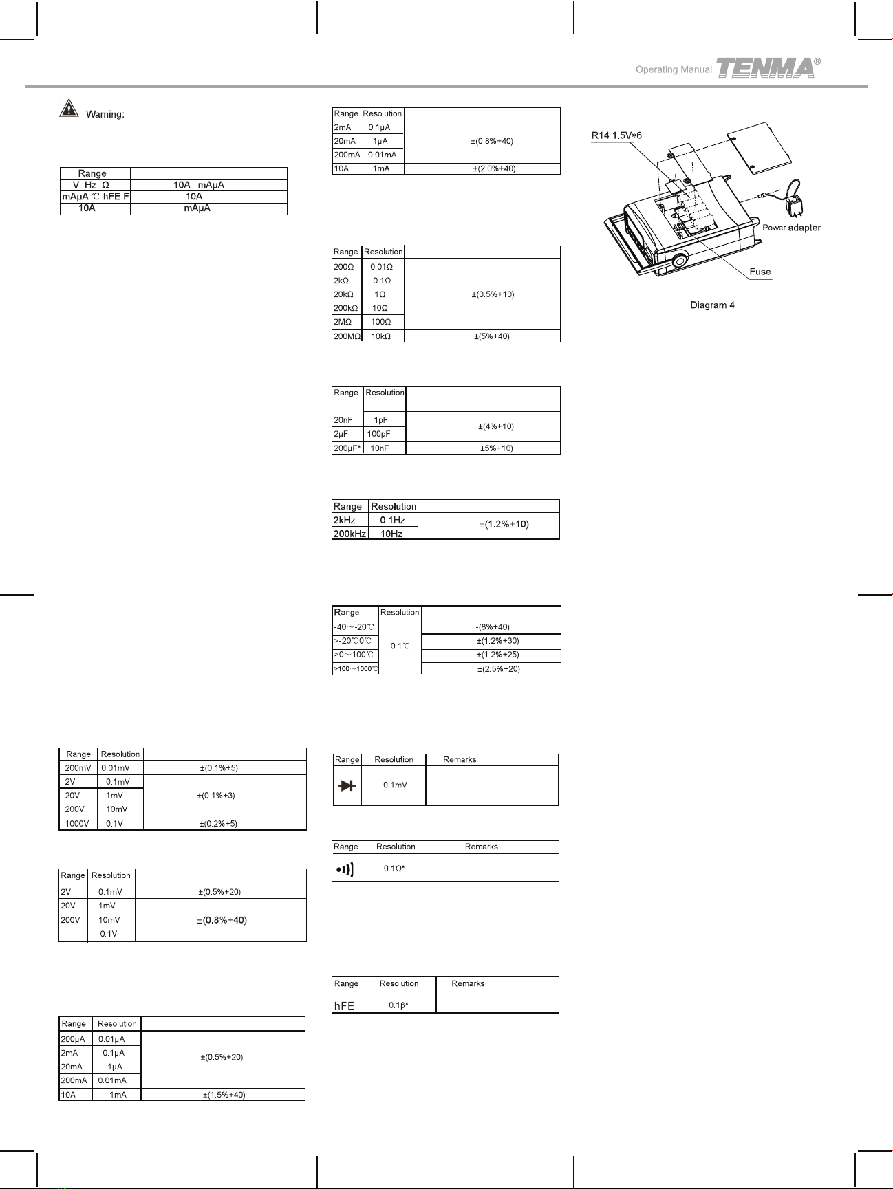
19. Power supply: AC (External power adapter
AC110V/ DC9V-200mA) or DC (Battery Size
R14/1.5V×6 PCS)
20. Product size: (300×245×105) mm
21 .Product Net Weight: about 1500g (accessories
not included)
22. Safety Compliance: IEC 61010: CATII 1000V
1. Manual Range Manual range indicator
2. Warning! Warning indicator
3. Low Battery
4. Indicator for high voltage
5. Indicator for negative reading
6. Indicator of AC voltage or
current (No display for DC
voltage or current)
7. Data hold activated
8. Test of diode
9. Continuity buzzer on
10. Decimal Number Showing the readout
11. Measurement units
72-14630
72-14630
Overview
Unpacking Inspection
General Specifications
Functional Buttons
Operational Guide (See Diagram 1, 2, 3)
LCD Display
Functions
Safety Notes
The Tenma 72-14630 Bench Top Digital Multimeter
features a 4 1/2 digit display with a maximum reading
of 19999. The large backlit LCD makes measurements
easy to read. The well-featured meter also provides
full range overload protection and dual power sources
(AC or DC battery). The unit can be used to test
AC/DC voltage, AC/DC current, resistance, frequency,
capacitance, temperature (Celsius), hFE transistors,
diode, and continuity test.
This operating manual includes relevant precautions and
safety information. Please read it carefully and strictly
observe all the Warnings and Safety Notes contained in
this manual.
Open the package and take out the unit. Check the
following items carefully to see if there is any missing or
damaged. If you find anything missing or damaged,
please contact your local dealer immediately.
● Operating Manual 1 Copy
● Test Lead 1 pair
● Short Test Lead with Alligator Clip 1 pair
● K Type Temperature Probe 1 piece
(Only applicable to test below 230℃)
● Socket Adaptor 1 piece
● Power Adapter 1 piece
(110VAC 60Hz (US) , 9VDC 200mA)
This unit is designed and produced in strict compliance
with IEC61010-1 code. As a unit with double insulation
over-voltage protection, it complies with the safety
standard contained in CAT II 1000V and Pollution
Degree II codes. Any failure to follow the operating
instruction contained in this manual may impair or void
the protection it has.
1 . Before use, the unit and test leads should be closely
inspected. If there appears to be any damage to either the
meter or test leads, do not attempt to use either. Do not use
the meter if the cover is removed, as it exposes the user to
2. If test leads are damaged, they must be replaced with
the one having identical model or electrical specifications.
3. Do not touch fingers or bare skin to any bare cables,
connectors, unused terminals, or circuits while being
tested.
4. When the meter is used at an effective voltage over 60V
in DC or 30V in AC, special care should be taken as there
is a danger of electric shock.
5. If the scope of the input value remains unknown, just
switch to the maximum range for testing.
6. No voltage or current exceeding the rated voltage or
current indicated by the unit should be applied between
test leads or between test lead and ground.
7. The rotary switch should be placed in the right position
and no changeover of range should be made during
measurement so as to prevent the damage of the unit.
8. Do not use or store the unit in an enviroment with high
temperatures, high humidity, flammable materials,
or excessive exposure to magnetic or radioactive field.
Unit of voltage: millivolt, volt
Unit of current: microampere,
milliampere, ampere
Unit of electrical resistance: Ohm,
kilohms, megohm
Unit of electrical capacity: nanofarad,
microfarad
Unit of frequency: Kilohertz
Unit of temperature: Celsius degree
Unit of triode amplification: times
Terminal Input Explanation
DC voltage measurement
AC voltage measurement
Resistance measurement
Frequency measurement
Diode/continuity test using
buzzer
(Use socket adaptor)
mA/μA for DC current measurement
A for DC Current measurement
mA/μA for AC current measurement
A for AC current measurement
Capacitance measurement
Temperature measurement
Power switch
Press Hold to enter or exit the hold mode when in
any mode, the meter beeps.
Backlight on or off (battery powered, backlight remain
on about 10 seconds before auto shut down.)
Triode amplification times
measurement
the risk of electric shock.
damage
2.DC or AC Voltage Measurement
3. DC or AC Current Measurement
4. Measuring Resistance, Diodes, Continuity or
Capacitance
Technical Specifications
1. DC Voltage
4. AC Current Replacing the battery or the fuse (See Diagram 4)
5. Resistance
6. Capacitance
7. Frequency
8. Temperature
9. Diode Test
10. Continuity Test
11. Triode hFE
2. AC Voltage
3. DC Current
72-14630
Tenma Test Equipment
300 S. Riverside Plaza #2200
Chicago IL, 60606
USA
www.Tenma.com
Alarm sounds on false terminal input
1. Please select correct terminal input and also turn the
rotary switch to select correct measuring function and
range. If not, the buzzer beeps and the warning signal
flashes.
● To avoid personal injury or damage to the unit due to
electric shock, please do not attempt to measure any
voltage higher than 1000 V though reading may be
obtained.
● The unit has an input impedance of approximately
10MΩ (ACV input impedance of approximately 2MΩ),
which can cause measurement errors for high impedance
circuits, so input impedance must be taken into account.
● Before measuring the current, the circuit under test
should be de-energized first. Remember that it should be
connected in series with the circuit to be test.
● Never use it to measure current higher than 10A.
Though it is possible to get a readout for any current
below 20A, but it may damage the unit or endanger
yourself.
● For an accurate measurements, de-energize the circuit
to be tested and discharge any capacitors.
● When measuring a resistance equal or higher than
1MΩ, it is normal for the unit to take several seconds to
obtain a stable reading. In order to obtain a stable reading,
choose shorter test leads to carry out measurement.
● When measuring low resistance, the test leads and the
internal wiring of the unit will incur a resistance around
0.1Ω~0.2Ω. To obtain accurate reading, short-circuit the
test leads beforehand and record the reading obtained,
such reading should be deducted from the final readout to
ensure the accuracy of the measurement.
● If the diode to be tested is a silicon diode junction, it is
normal if the reading falls into a scope between 500mV
and 800mV. For continuity tests, if the resistance between
two terminals is greater than 100Ω, it is considered to be
an open circuit. If the resistance is less than 10Ω, then it
is a close continuous circuit, signaled by an audible alert.
The readout then is nearly equal to the resistance of the
circuit.
Accuracy: ± (% of the reading + digits), 1 year guarantee
Environmental temperature: 18℃~ 28`C
Environmental humidity: Less than 75% RH
Accuracy Tolerance:±(% of the reading + digits)
Input Impedance:Average 10MΩ
Maximum Voltage Input: 1000V (Except for 200mV 250V)
Accuracy Tolerance:±(% of the reading + digits)
Input Impedance: about 2MΩ.
Maximum Voltage Input: 750Vrms
Frequency: 45Hz~400Hz
Displays effective value of sine wave(mean value
response).
Accuracy Tolerance:±(% of the reading + digits)
* When ≥5A, continuous measurement should be less
than 10 seconds at an interval more than 15 minutes.
Accuracy Tolerance:±(% of the reading + digits)
* Frequency response: 45Hz~400Hz
When ≥5A, continuous measurement should be less
than 10 seconds at an interval more than 15 minutes.
Accuracy Tolerance:±(% of the reading + digits)
When >100MΩ, the result is for reference only.
Accuracy Tolerance:±(% of the reading + digits)
* When >40μF, the result is for reference only.
Accuracy Tolerance:±(% of the reading + digits)
Input Amplitude a:
(2kHz range) 50mV≤a≤30Vrms
(200kHz range) 150mV≤a≤30Vrms
Accuracy Tolerance:±(% of the reading + digits)
* Temperature Transducer: K type thermocouple
(Point contact, made of nickel-chromium or nickel-
silicon) is included as an accessory, which can only
be used to measure temperature less than 230℃.
Open circuit voltage is around 3V;
for Silicon P-N junction, 0.5~0.8V
is considered as a normal value.
Open circuit voltage is
approximately 3V
If the resistance between two terminals is tested to
be more than >100Ω, it is considered as open circuit,
the buzzer does not beep or it is in good connection
if it is equal or less than ≤10Ω, the buzzer keeps
beeping.
1 b0 is about 10μA, Vce is
about 2.5V
Specifications and safety information contained in this
manual are subject to change without further notice.
750
P/N:110401108720X
REV.0
Aug.2019
序号 项目 内容
1
2
3
4
5
6
7
尺寸 展开尺寸:(210x285)±1mm.折叠成形尺寸:(70*142.5)±1mm
60g书纸
黑色
印刷完整清晰,版面整洁.无分层.残损.毛边等缺陷
按折叠线折叠
无
邓捷睿19/8/6
材质
颜色
外观要求
装订方式
表面处理
其它
版本
DWH
设 计 MODEL
机型:
Part NO.
物料编号:110401108720X
CHK
审 核
APPRO.
批 准
说明书菲林做货要求:
0
72-14630(UT802改)
客说明书

Other Tenma Multimeter manuals

Tenma 72-1015 User manual

Tenma

Tenma 72-1015 User manual

Tenma 72-3540 User manual

Tenma

Tenma 72-3540 User manual

Tenma UT202 User manual

Tenma

Tenma UT202 User manual

Tenma 72-7720 User manual

Tenma

Tenma 72-7720 User manual

Tenma UT60C User manual

Tenma

Tenma UT60C User manual

Tenma 72-10405 User manual

Tenma

Tenma 72-10405 User manual

Tenma 72-8150 User manual

Tenma

Tenma 72-8150 User manual

Tenma TEN01061 User manual

Tenma

Tenma TEN01061 User manual

Tenma 72-10395 User manual

Tenma

Tenma 72-10395 User manual

Tenma 72-9375 User manual

Tenma

Tenma 72-9375 User manual

Tenma 72-7780 User manual

Tenma

Tenma 72-7780 User manual

Tenma 72-1016 User manual

Tenma

Tenma 72-1016 User manual

Tenma 72-8720 User manual

Tenma

Tenma 72-8720 User manual

Tenma 72-3530 User manual

Tenma

Tenma 72-3530 User manual

Tenma 72-8720 User manual

Tenma

Tenma 72-8720 User manual

Tenma 72-10465 User manual

Tenma

Tenma 72-10465 User manual

Tenma 72-3097 User manual

Tenma

Tenma 72-3097 User manual

Tenma 72-8495 User manual

Tenma

Tenma 72-8495 User manual

Tenma 72-7930 User manual

Tenma

Tenma 72-7930 User manual

Tenma 72-1055 User manual

Tenma

Tenma 72-1055 User manual

Tenma 72-7730A User manual

Tenma

Tenma 72-7730A User manual

Tenma 72-7224 User manual

Tenma

Tenma 72-7224 User manual

Tenma 72-8155 User manual

Tenma

Tenma 72-8155 User manual

Tenma 72-7740 User manual

Tenma

Tenma 72-7740 User manual

Popular Multimeter manuals by other brands

AEMC C.A 5205 user manual

AEMC

AEMC C.A 5205 user manual

Wavetek Meterman DM78A Operator's manual

Wavetek

Wavetek Meterman DM78A Operator's manual

Global Specialties PRO-50A manual

Global Specialties

Global Specialties PRO-50A manual

Extech Instruments EX503 user guide

Extech Instruments

Extech Instruments EX503 user guide

GALLUNOPTIMAL SKALA 400 user manual

GALLUNOPTIMAL

GALLUNOPTIMAL SKALA 400 user manual

Mastech MS8232B user manual

Mastech

Mastech MS8232B user manual

SBS 600 user manual

SBS

SBS 600 user manual

McCheck DM-312 Reference manual

McCheck

McCheck DM-312 Reference manual

DPM DT803X manual

DPM

DPM DT803X manual

LIMIT 610 operating manual

LIMIT

LIMIT 610 operating manual

HoldPeak 850E Operation manual

HoldPeak

HoldPeak 850E Operation manual

Aktakom ??M-1130 user manual

Aktakom

Aktakom ??M-1130 user manual

Amprobe AM-560 user manual

Amprobe

Amprobe AM-560 user manual

Projecta DT200 manual

Projecta

Projecta DT200 manual

SEFRAM 7341 user manual

SEFRAM

SEFRAM 7341 user manual

Innova 3320 owner's manual

Innova

Innova 3320 owner's manual

CEM DT-113 instruction manual

CEM

CEM DT-113 instruction manual

Klein Tools MM2000 instruction manual

Klein Tools

Klein Tools MM2000 instruction manual

manuals.online logo
manuals.online logoBrands
  • About & Mission
  • Contact us
  • Privacy Policy
  • Terms and Conditions

Copyright 2025 Manuals.Online. All Rights Reserved.