Copyright © 2017 Aqua Creek Products All Rights Reserved Revised 12/4/17
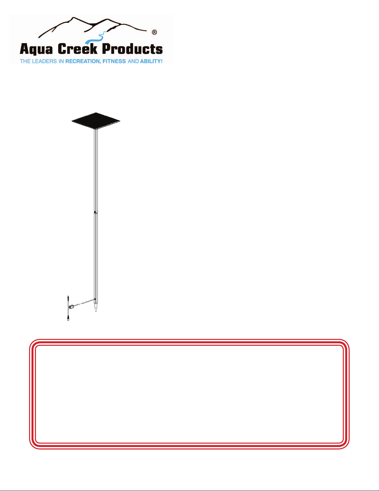
24V Solar Charger
Instructions
9889 Garrymore Ln
Missoula, MT 59808
888-687-3552 | +1-406-549-0769
www.aquacreek.com
PART #: F-044SCH
(For use with Pro Pool, Ranger,
Ambassador & Pathfi nder)
MANDATORY
LEAVE THIS MANUAL WITH LIFT OWNER
Read and follow all instructions.
Lift safety can only be ensured if the lift is installed and
operated according to these instructions.
• NEVER permit children to play on or around the lift
• Do not allow children to use the lift without adult
supervision
• NEVER apply direct water pressure to the electronics
• NEVER use the lift with a dry pool
Check entire box and all packing materials for parts. Before beginning assembly, read the
instructions and identify parts using the fi gures and parts listed in this document.
It is critical that all parts be carefully inspected prior to installation. If any damage occurred in
transit, Aqua Creek Products, LLC must be notifi ed within three days of receipt of unit.
Proper installation cannot be overstressed, as an improper installation voids Aqua Creek’s
warranty and may affect the safety of the user.
READ CAREFULLY
1