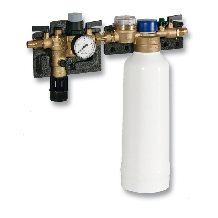
Truma AquaGo Electric antifreeze kit User manual

Electric antifreeze kit AquaGo™
US
Table of Contents
Intended use .......................................................................... 2
Safety Information ................................................................ 2
Scope of delivery ................................................................... 4
Installation instructions ....................................................... 5
Preparing for installation .......................................................... 5
Installing the holder .................................................................. 5
Installing the heating cartridge ................................................. 6
Electrical installation ................................................................. 8
Operating instructions ........................................................ 10
Start-up ................................................................................... 10
Troubleshooting .................................................................. 13
Change over to gas mode ...................................................... 13
Dismantling the electric antifreeze kit .................................... 14
CA, MX
Technical data ...................................................................... 18
“Electric antifreeze kit”
MANUFACTURER LIMITED WARRANTY ........................ 18

2
Safety Information
The operating instructions supplied with the
Truma AquaGo™ instant water heater are part
of these installation and operating instructions
for the Truma electric antifreeze kit.
Read and follow all of this information
to avoid injuries during installation and
operation.
Safety symbols and signal words
This is the safety alert symbol. This symbol
alerts you to potential hazards that can kill or
hurt you and others.
indicates a hazardous situation
which, if not avoided, could result in minor or
moderate injury.
is used to address practices not
related to physical injury.
Intended use
The Truma electric antifreeze kit* keeps the
Truma AquaGo™ instant water heater frost-
free to -4 °F (-20 °C) while you are driving or if
there is no gas supply. To operate the Truma
antifreeze kit you need a 12V (minimum 120 W
recommended) power supply from the RV’s on-
board system.
* For AquaGo™ comfort / AquaGo™ comfort plus
The Truma electric antifreeze kit protects
only the water in the Truma AquaGo instant
water heater against freezing. The Truma elec-
tric antifreeze kit will not protect the RV’s entire
water system. Water lines, faucets, water tanks
and the external water valves and the vehicle
must be heated separately.

3
Other important information or tips
Installation and service must be performed
by an expert. Improper installation, altera-
tion, service or maintenance can cause prop-
erty damage, personal injury or loss of life.
California Proposition 65 lists chemical sub-
stances known to the state to cause cancer,
birth defects, death, serious illness or other re-
productive harm. This product may consist of
such substances or such substances may be
formed from components of the product.

4
Scope of delivery
Quantity Component
1 Electric antifreeze kit cartridge
(heating cartridge)
1 Adapter cable
1 Plug
1 Holder
2 Cable ties (not shown)
1Installation/Operating instructions
for the Truma electric antifreeze kit
Top
Connector X1 Contact socket
Connection cable
Heating cartridge
O-rings
Latch
Connector X2
Plug
Holder
Lug
Adapter cable
Fig. 1

5
Installation instructions
You will find more information about the
following in the operating instructions for
the Truma AquaGo™ instant water heater:
• Operation
• Access door
• Draining the water
Preparing for installation
1. Remove the access door.
2. Switch OFF the Truma AquaGo™ instant
water heater at the POWER switch and at the
control panel (set Operating mode to OFF).
Installing the holder
3. Attach the holder to the rear side of the ac-
cess door, as shown in Figure 2.
• Undo the two screws of the webbing
about 1/10 inch (2.5 mm).
• Position the holder below the screws.
• Tighten the screws.
Screws
Holder
Holder
Webbing
Access
door
Fig. 2

6
4. Clamp the plug beneath the holder, as
shown in Figure 3.
Holder
Plug
Lug
Access
door
Fig. 3
Installing the heating cartridge
1. Turn OFF the water supply or switch OFF the
water pump.
2. Open a hot water faucet and leave it open in or-
der to depressurize and vent the water system.
3. Injuries caused by the
Easy Drain Lever! When the Easy Drain
Lever is folded out, it protrudes beyond the
side wall of the vehicle.
• When walking past or bending over,
make sure that you and others have suf-
ficient distance.
4. Open the latch with your thumb while pulling
the Easy Drain Lever down as far as it will go.
5. Remove the water inlet filter as shown in
Fig. 4a and rinse it with clean water.
Keep the water inlet filter in a safe place.
When you decalcify the TrumaAquaGo™
instant water heater, you will need it for the
Truma AquaGo™ decalcification tablets.
6. Inspect the O-rings on the heating cartridge
for cracks. Replace the heating cartridge if
there are cracks.

7
7. Danger of crushing/pinch-
ing of fingers when the Easy Drain Lever
is closed!
• Never put fingers between Easy Drain
Lever and water inlet filter or latch.
If during installation, it is difficult to in-
stall the heating cartridge, use a small
amount of soap on the O-rings. Never use
grease, because the O-rings are not resist-
ant to grease.
1
2
Easy Drain Lever
Water inlet filter
Latch
Fig. 4a

8
Top
Latch
O-rings
Heating cartridge
Connection cable
Connector X1
Fig. 4b
8. Risk of a short circuit!
• Lay the connection cable upward so that
it is not jammed when the Easy Drain
Lever is closed.
9. Install the heating cartridge as shown in
Fig. 4b. Observe the correct installation
position and close the Easy Drain Lever
until it is locked by the latch. You can hear
a “clicking” sound as the EasyDrain Lever
engages.
Electrical installation
(“adapter cable”)
1. Damage to the contact sockets
resulting from incorrect installation.
• During installation, you must align the
contact sockets as shown in Figure 5.
• Remove the socket housing from the con-
trol unit (press the lock).

9
2. Slide the contact sockets (see Figure 5) into
the socket housing (openings 1 and 11) until
they lock in place. You do not have to bother
about the plus and minus poles.
3. After installation, lightly pull the adapter
cable to make sure that the contact sockets
are locked in place.
4. You must attach the socket housing to the
control unit again when you have removed
it. It must lock in place.
5. Lay the adapter cable and fix it in place with
the 2 cable ties, as shown in Figure 5.
6. Connect the connection cable to the adapter
cable (see Figure 5).
Lug
Socket housing
Contact socket
Connector X1
Lock
1
Cable tie
Connector X2
Adapter cable
Fig. 5
7. Installation is complete.

10
Operating instructions
For proper operation, you must observe the
following:
• Gas must not be used for heating
while the RV is in motion.
• With this electric antifreeze kit, the
TrumaAquaGo™ instant water heater can
be kept frost-free while you are driving or
if there is no gas supply (to ambient tem-
peratures of -4 °F (-20 °C)).
• At ambient temperatures below -4 °F (-20 °C)
the Truma AquaGo™ instant water heater
must not be operated and must be winterized.
You will find more information about the
following in the operating instructions for
the Truma AquaGo™ instant water heater:
• Operation
• Operating modes
• Winter operation / winterizing
• Troubleshooting
• Access door
• Draining the water
Start-up
1. Remove the access door.
2. Switch OFF the Truma AquaGo™ instant
water heater at the POWER switch and at
the control panel (set Operating mode to OFF).
3. Allow the Truma AquaGo™ instant water
heater to cool down
4. Risk of damage in frosty con-
ditions without plug!

11
• Never operate the electric antifreeze kit
without an installed plug in the flue duct.
(The plug prevents cold air from flowing
through the heat exchanger).
5. Remove the plug from the holder and close
the flue duct with it (see Figure 6).
6. You may have to connect the connection
cable to the adapter cable (see Figure 5).
Plug
Flue duct
Lug
Fig. 6
7. To operate the antifreeze kit, fill the
TrumaAquaGo™ instant water heater with
water and switch it on. (See “Winter oper-
ation” in the operating instructions for the
Truma AquaGo™ instant water heater.)
• Close open bypass lines (if present).

12
• Turn on fresh water supply or switch on
water pump.
• Fill the water system.
• Malfunction of the electric
antifreeze kit due to air in the water
system
– Vent the water system so that the cir-
culation pump in the Truma AquaGo™
instant water heater works.
• Open all water-release points, e.g., cold
and hot water faucets, showers, toilets.
• Once water flows uniformly, the water
system is vented. Close the water-release
points.
8. Switch ON the Truma AquaGo™ instant wa-
ter heater at the POWER switch.
9. Insert and close the access door.
10.Check the position of the plug. You must be
able to see the lug through the venting grid
– as shown in Figure 7.
Lug
Venting grid
Fig. 7
11.Select operating mode ANTIFREEZE (see
Figure 8).
LED 3
Rotary switch
ANTIFREEZE
Fig. 8

13
• During operation, the yellow status LED 3
(see Fig. 8 - LED 3) is lit.
Troubleshooting
Problem Potential cause
The Truma AquaGo™
instant water heater
does not start in gas
mode.
– The plug is blocking
the flue duct.
Remove the plug from the flue duct and clamp
it beneath the holder (see Figure 9).
The yellow status
LED 3 is not lit. – The heating cartridge
is not attached or is
defective.
Check the connection on connector X1. You
may have to disconnect it and connect it again.
The yellow status
LED 3 is flashing. – There is a
malfunction.
See “Description of the yellow status LED 3”
in operating modes (control panel) in the op-
erating instructions for the Truma AquaGo™
instant water heater.
If none of the measures in the troubleshooting
chart proves successful, please contact your
dealer, the Truma Service Center on 1-855-558-
7862 or one of our authorized service partners.
Change over to gas mode
If you change the Truma AquaGo™ instant
water heater back to gas mode, the heat-
ing cartridge can remain in the Truma AquaGo™
instant water heater.
1. Remove the access door.
2. Switch OFF the Truma AquaGo™ instant
water heater at the POWER switch and at the
control panel (set Operating mode to OFF).
3. Remove the plug from the flue duct and
clamp it beneath the holder (see Figure 9).

14
Plug
Lug
Holder
Fig. 9
4. Switch ON the Truma AquaGo™ instant wa-
ter heater at the POWER switch.
5. Insert and close the access door.
6. The Truma AquaGo™ instant water heater is
now ready for using the control panel inside
your vehicle.
Dismantling the electric antifreeze kit
For decalcification you must use the water inlet
filter (included with the delivery of the Truma
AquaGo™ instant water heater).
1. Remove the access door.
2. Switch OFF the Truma AquaGo™ instant
water heater at the POWER switch and at the
control panel (set Operating mode to OFF).
3. Turn OFF the water supply or switch OFF the
water pump.
4. Open a hot water faucet and leave it open
in order to depressurize and vent the water
system.

15
5. Remove the plug from the flue duct and
clamp it beneath the holder (see Figure 9).
6. Unplug the connector X1 (see Fig. 10).
Connector X1
Fig. 10
7. Injuries caused by the
Easy Drain Lever! When the Easy Drain
Lever is folded out, it protrudes beyond the
side wall of the vehicle.
• When walking past or bending over,
make sure that you and others have suf-
ficient distance.
8. Open the latch with your thumb while pulling
the Easy Drain Lever down as far as it will go.
9. Remove the heating cartridge as shown in
Fig. 11a and rinse it with clean water.

16
1
2
Easy Drain Lever
Latch
Heating cartridge
Fig. 11a
Latch
O-rings
Water inlet filter
Top
Fig. 11b

17
10.If you now want to decalcify the
TrumaAquaGo™ instant water heater,
the removal of the electric antifreeze kit is
complete.
You can find more information about
decalcification in the operating instructions
for the Truma AquaGo™ instant water heater in
“Decalcification (models with control panel)”.
11.Inspect the O-rings on the water inlet filter
for cracks. Replace the water inlet filter if
there are cracks.
12. Danger of crushing/pinch-
ing of fingers when the Easy Drain Lever
is closed!
• Never put fingers between Easy Drain
Lever and water inlet filter or latch.
If during installation, it is difficult to in-
stall the heating cartridge, use a small
amount of soap on the O-rings. Never use
grease, because the O-rings are not resis-
tant to grease.
13.Install the water inlet filter as shown in
Fig. 11b. Observe the correct installation
position and close the Easy Drain Lever until
it is locked by the latch.
You can hear a “clicking” sound as the
EasyDrain Lever engages.
14.Insert and close the access door.
15.Removal of the electric antifreeze kit is
complete. You can find information about
operation of the Truma AquaGo™ instant
water heater in “Operating procedures”
in the operating instructions for the
TrumaAquaGo™ instant water heater.

18
Technical data
Nominal voltage 12 VDC
Nominal current 5 A
Ambient temperature -4°F…+104°F
(-20°C…+40°C)
Dimensions
Width 2.8 inch (72 mm)
Height 2.0 inch (50 mm)
Depth 9.1 inch (230 mm)
Weight (approx.) 0.5 lbs (220 g)
TRUMA Gerätetechnik GmbH & Co. KG
(“TRUMA”)
“Electric antifreeze kit”
MANUFACTURER LIMITED
WARRANTY
(September 2014)
This limited warranty pertains solely to the
“electric antifreeze kit” (the “Product”) manu-
factured by TRUMA and sold through its affili-
ates and dealers in North America.
TRUMA warrants subject to the below stated
conditions that the Product will be free from
defects in material and workmanship, and will
perform in accordance with the technical speci-
fications set forth in the description of the Prod-
uct for a period of twelve (12) months for newly
manufactured parts from the original date of
purchase. This limited warranty shall only apply

19
if the Product was properly installed according
to the installation instructions provided and in
compliance with applicable codes.
During the warranty period, TRUMA will repair
or replace, at its own discretion and costs, the
defective Product or parts or components of
such Product reported to TRUMA and which
TRUMA determines was defective due to a war-
ranty defect. Costs of diagnosis for a warranty
defect are borne by TRUMA. Other costs of di-
agnosis are not included in this warranty. At the
discretion of TRUMA, the replacement of the
Product or parts or components thereof (i) may
be newly manufactured, (ii) may be assembled
from new or serviceable used parts that are
equivalent to new parts in performance, or (iii)
may have been previously installed.
The customer shall not attempt to repair
the Product or resolve the problem without
the prior consent of TRUMA. Any attempt
by the customer to repair the Product or
resolve the problem without the prior con-
sent of TRUMA will void this warranty.
This limited warranty does not cover any defects
attributable in whole or in part to (i) non-TRUMA
products and services and / or alterations of out-
of-specification supplies, (ii) accidents, misuse,
negligence or failure of the customer to follow in-
structions for the proper use, care and cleaning of
the Product, (iii) damages caused in gas pressure
regulation systems due to foreign substances in
the gas (i.e. oil, plasticizers), (iv) external factors
(e.g., fire, flood, severe weather), (v) failure of
proper transport packaging, or (vi) failure by the
purchaser to comply with TRUMA’s installation
and user manual regarding the Product.
All warranty claims must be reported to TRUMA’s
authorized warranty service center in the United
States: Truma Corp Service Center, 825 East
Jackson Blvd., Elkhart, IN 46516, toll free:
(855) 558-7862, fax. (574) 538-2426,
[email protected], www.truma.net

20
The purchaser shall provide the following
information regarding the potential warranty
claim (i) serial number of the defective device,
(ii) proof of purchase, (iii) purchaser’s contact
information.
EXCEPT AS EXPRESSLY STATED AND SET
FORTH HEREIN, THERE ARE NO WARRAN-
TIES OR REPRESENTATIONS, EXPRESS OR
IMPLIED, CONCERNING THE PRODUCT
AND NO SUCH WARRANTIES OR REPRE-
SENTATIONS SHALL BE IMPLIED UNDER
ANY APPLICABLE LAW, IN EQUITY OR
OTHERWISE, INCLUDING WITHOUT LIMI-
TATION, A WARRANTY OF MERCHANT-
ABILITY, A WARRANTY OF FITNESS FOR
A PARTICULAR PURPOSE, OR ANY OTHER
WARRANTY WHICH MAY BE IMPLIED UN-
DER COMMON LAW OR UNDER THE UNI-
FORM COMMERCIAL CODE OF ANY STATE
OR OTHER JURISDICTION OF THE UNITED
STATES OF AMERICA.
Unless further limited herein, the entire liability
of TRUMA and the customer’s exclusive remedy
for damages from any cause related to or
arising out of a warranty defect, regardless of
the form of action, whether in contract or in
tort, will not exceed the amount of the purchase
price for each purchase order for the Product
which is the subject matter or directly related to
the causes of action asserted.
Unless prohibited under applicable state law, in
no event will TRUMA, its agents, subcontrac-
tors, affiliates, suppliers and employees be li-
able for (a) any incidental, indirect, special or
consequential damages, including, but not lim-
ited to, loss of use, revenue, profits or savings,
substitute rental or for any other reason, even if
TRUMA knew or should have known of the pos-
sibility of such losses or damages, (b) claims,
demands or actions against the customer by any
person, except as provided by applicable law.
Table of contents
Languages: