Taco EWF-120-1 User manual

Listings/Approvals:
• UL GUIDE (MBPR) for Limit Controls per UL Standard
353 Limit Controls
• CUL per CSA Standard C22.2 No. 24-93 for tempera-
ture indicating and regulating equipment.
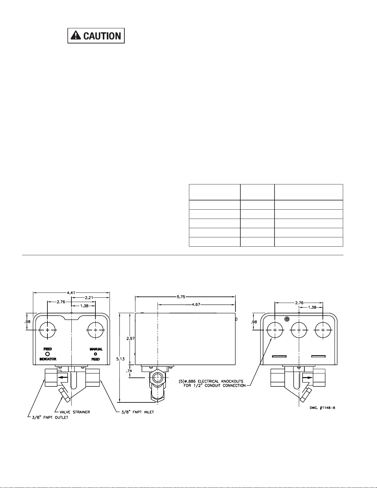
Process Connections: 3/8" FNPT or 3/8” NPT to 1/2" copper
fittings (included)
Enclosure:
NEMA Type 1 (For indoor use only.) Formed sheet metal
with powder coat/plated finish. Five openings for 1/2"
conduit fittings. (Not for use in hazardous locations.)
Maximum Inlet Pressure:
Maximum Outlet (Boiler) Pressure:
Maximum Media Temperature:
Maximum Ambient Temperature:
Feed Rate:
Feed Choices: LWCO Mode, Fixed Feed, or Manual Feed
Flood Protection Lockout
Excess Feed Indicator
GENERAL
The Electric Water Feeder (EWF), is an electronics based
water feeder for steam boilers. The EWF monitors the output
from a Low Water Cutoff (LWCO). When the LWCO detects a
low water condition, it signals the EWF, which initiates a
water-feed cycle. Since the EWF is fully programmable, it can
feed as long as the low water cutoff detects a low water
condition (LWCO mode) or fixed feed amounts. In addition,
the EWF allows the user to set Delays Before Feeding (DBF),
or hold delays after the low water cutoff signals water is
restored (HAW). The EWF also includes a programmable
excess feed indicator, (patent pending). The EWF blinks this
LED after it has fed more than a settable number of gallons
into the boiler over the past 30 days. This will help identify
systems that may need maintenance.
Instruction Sheet
Electric Water Feeder 102-170
SUPERCEDES:REVISIONDATEDAUGUST1,2004
#5401148-REVB EFFECTIVE:NOVEMBER10,2004
:rewoPtupnI
ledoMegatloV rewoP noitpmusnoC
1-021FWECAV021AV21
1-420FWE**CAV42AV01
Patent Pending
** 24 VAC to be supplied by an EXTERNAL Class 2 power source
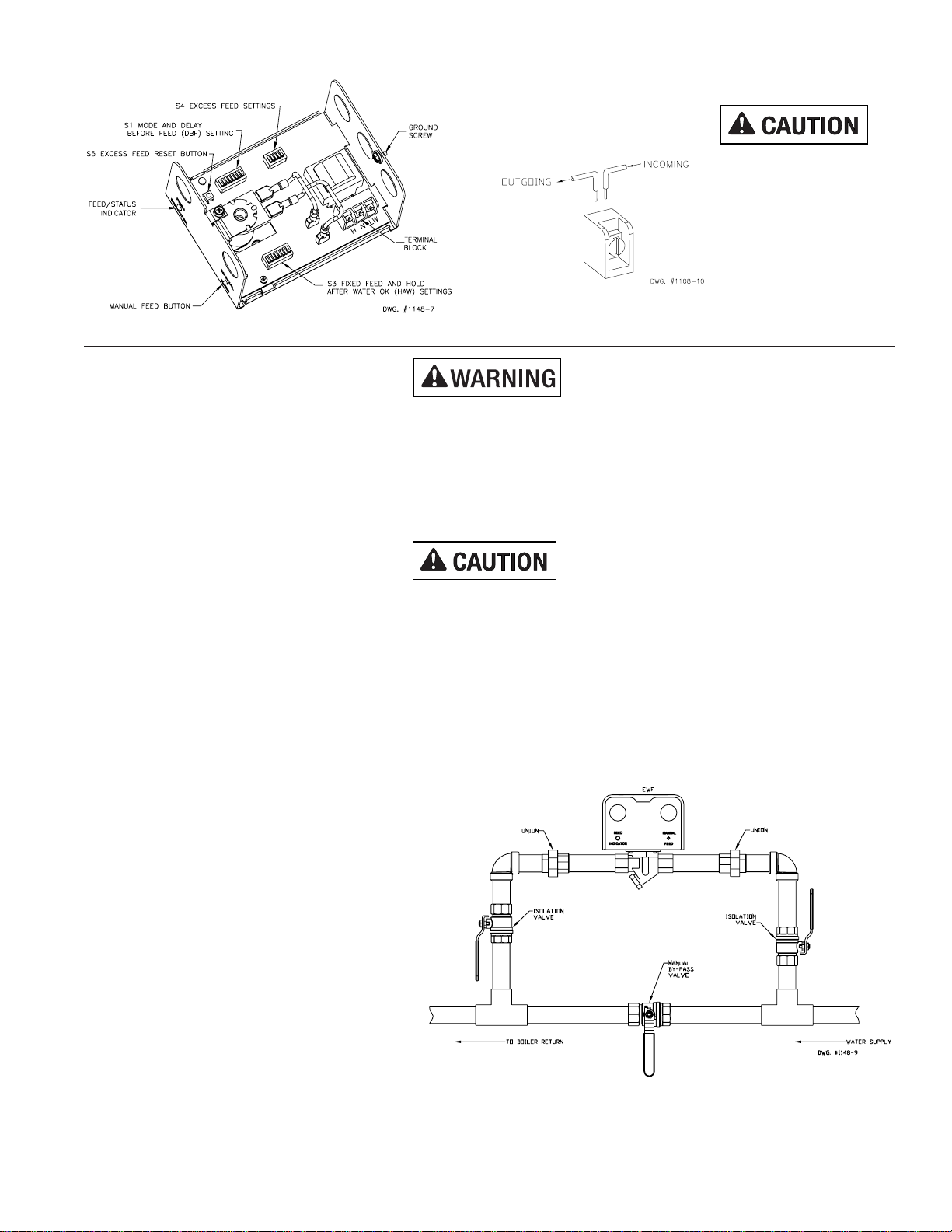
OPERATION
LWCOMode
When the mode switch of S1 (See fig. 9a) is set to the ON
position, the EWF will operate in LWCO mode. This causes
the EWF to feed water whenever the LWCO signals a low
water condition. Both the Delay Before Feeding (DBF), and
the Hold After Water OK (HAW), settings may be set in LWCO
mode. As soon as the EWF receives a low water signal from
the LWCO, the EWF starts feeding water to the boiler after
the DBF delay expires, if enabled. The EWF continues
feeding water to the boiler until the LWCO signals that the
water condition is normal and any HAW delay expires. If the
EWF feeds 10 gallons, Flood Protection Lockout occurs and
feeding stops immediately and a red LED is illuminated.
FixedFeed
When the mode switch of S1 is set to the OFF position, the
EWF will operate in Fixed Feed, (FF), mode. While in this
mode, the EWF will feed the number of gallons set by switch
S3 (See fig. 9a & c). While in Fixed Feed mode, only DBF
delays may be used. HAW settings only apply to LWCO
mode. After a feed cycle completes, if the LWCO still signals
a low water condition, the EWF will start another feed cycle. If
the EWF completes the second feed cycle and the LWCO still
signals a low water condition, the EWF will enter the Flood
Protection Lockout and a red LED is illuminated.
150 PSI (10.5kg/cm2)
15 PSI (1kg/cm2)
160°F (71°C)
100°F (38°C)
1 gpm (3.8 lpm)

CONTROLUNITOUTLINEDRAWING
FIG. 1
noitidnoC DELsutatS roloC etatS
lamroN/rewoPneerGydaetS
gnideeFneerGdnocesrepsemitowt-gniknilB
deeFssecxErebmAdnocesrepsemitruof-gniknilB
tuokcoLnoitcetorPdoolFdeRydaetS
eruliaFlortnoCdeRdnocesyreveecno-gniknilB
•If the LWCO signals a normal water
condition while the EWF is feeding a fixed
amount,theEWFwill NOTstopfeeding
until the number of gallons set at DIP
switch S3 has been fed to the boiler. Be
sure S3 is set to feed the correct amount
of water.
•Floodingor property damage may result.
ManualFeed
The Manual Feed button on the EWF allows the user to
manually feed water to the boiler system as long as the user
presses the button. Up to 5 gallons may be manually fed
continuously before the EWF automatically closes the feed
valve. If the EWF automatically closes the feed valve, the
Manual Feed button must be released and re-pressed to
manually feed more water. Manually fed water counts
towards Excess Feed settings.
ExcessFeedIndication
The Feed/Status Indicator will be rapidly blinking amber
when the EWF has dispensed more water over the past 30
days than the setting of the Excess Feed switch (S4).
Pressing and holding switch S5 will reset the Excess Feed
Condition. See Fig. 2 for location of Excess Feed Reset
Button. Once this reset button is pressed and held for 2
seconds the EWF briefly turns off the Feed/Status Indicator
indicating reset has occurred. Once the EWF completes the
reset process, the Feed/Status Indicator will resume its
normal state. Once the EWF is installed and the system is
filled with water, reset the Excess Feed Condition to start
normal operation of the system.
FloodProtectionLockout
If the EWF dispenses 10 gallons in LWCO mode or
completes two feed cycles in Fixed Feed mode, without the
LWCO signaling a normal water level, the EWF enters Flood
Protection Lockout. In this condition the EWF shuts off its
feed valve, illuminates the Feed/Status Indicator LED to red,
and waits for the user to correct the problems and reset the
EWF. Entering the Flood Protection Lockout prevents
flooding the boiler in the event that water is not actually
needed by the boiler. Pressing and holding the Manual Feed
button for 2 seconds will reset the Flood Protection Lockout
condition. See Fig. 2 for location of the Manual Feed button. If
the EWF enters Flood Protection Lockout, the user must
trouble-shoot the system and correct the cause of the
condition.
Feed/StatusIndicator
A multi-color LED indicates the status of the EWF as follows:
(2)

EWF
FIG. 2
••
••
•Shock hazard. Disconnect power source before servicing. Serious injury or death could result.
••
••
•Installation must be performed by qualified personnel and in accordance with all national and local codes
andordinances.
••
••
•Not for use in hazardous locations.
••
••
•To prevent damage to the device and/or electrical fire, wire insulation must be rated at 167° F (75° C) – over
copper wire only.
••
••
•When installations are complete, check for correct operation of ALL limit and operating controls!
••
••
•Read all instructions carefully and understand them before starting installation and save for future use.
••
••
•Instruct user how to test and operate this feeding device as described in these instructions.
••
••
•Do not use manual reset low water cutoff with automatic water feeders like the EWF or flooding and prop-
erty damage can occur.
••
••
•If using mixed voltages, DO NOT install jumper wire on LWCO.
••
••
•Wire the water feeder and low water cutoff from the same power sources. Failure to do so could result in
flooding and property damage can occur
INSTALLATION
Piping
Plumb the EWF water feeder as shown in Figure 4.
The EWF must be installed with a manual bypass.
To permit ease of removal for servicing or replace-
ment, install unions and isolation valves. Install
the EWF with the flow direction arrow toward the
boiler. Fill the boiler by manually opening the
bypass valves until the water level is at a normal
level for the boiler, (refer to the boiler
manufacturer’s literature for proper fill levels).
Check the system for leaks before proceeding.
Once the system is full, close the bypass valve and
verify that both isolation valves are open. This
routes water through the EWF.
TERMINALBLOCK CONNECTIONS
CLAMPINGPLATETERMINAL
FIG. 3
An uninsulated section of a
single conductor should not be
looped around the terminal and
serve as two separate
connections. The wire must be
severed, thereby providing
supervision of the connection
in the event that the wire
becomes dislodged from under
the terminal. Use 18 AWG
(min.), or as required by local
code. Wire insulation rating
must be at least 167°F (75°C).
FIG. 4
(3)

••
••
•Shock hazard. Disconnect power source
before servicing. Serious injury or death
couldresult.
EWF Wiring
Standard Wiring –EWF to LWCO with same voltages, see
Figure5.
1. Verify that the supply and burner circuit voltages con-
nected to the LWCO are the same as the EWF
2. Verify that factory-installed jumpers connecting the hot
lead on the LWCO to the burner source are installed.
3. Connect the hot lead wire from the power source to
terminal H on the EWF.
4. Connect the neutral lead wire from the power source to
terminal Non the EWF.
5. Connect the NO/water feeder/alarm terminal on the
LWCO to terminal LW on the EWF.
Wiring EWF to LWCO with different burner circuit voltages,
see Figure 6a & b.
1. Verify that the burner circuit voltages connected to the
LWCO are the same as the EWF
2. Verify that factory-installed jumpers connecting the hot
lead on the LWCO to the burner source are removed.
3. Connect the hot lead wire from the burner power source
to terminal H on the EWF.
4. Connect the neutral lead wire from the burner power
source to terminal Non the EWF.
5. Connect the NO/water feeder/alarm terminal on the
LWCO to terminal LW on the EWF.
NC COM NO H N
Taco LTx120x / LTx024x
GND P
BURNER
CIRCUIT
HOT
NEUTRAL
HN
Taco EW F120 / EW F024
LW
120 VAC / 24 VAC
CIRCUIT
FIG. 5
FIG. 6
(b)
(4)
(a)
NC COM NO H N
Taco LTx120x
GND P
BURNER
CIRCUIT 120 VAC
CIRCUIT
HOT
NEUTRAL
H N
Taco EW F024
LW 24 VAC
CIRCUIT
HOT
NEUTRAL
NC COM NO H N
Taco LTx024x
GND P
BURNER
CIRCUIT
120 VAC
CIRCUIT
HOT
NEUTRAL
H N
Taco EW F120
LW
24 VAC
CIRCUIT
HOT
NEUTRAL
*
*
* NOTE: Remove factory installed
jumper between H and COM terminals
EWF Standard Wiring
EWF Alternate Wiring
FIG. 7
(a) (b)
NC COM NO H N GND P
BURNER
CIRCUIT
HOT
NEUTRAL
HNLW
120 VAC
CIRCUIT
NHC WB
McDonnell & Miller
PS-801/851-120
w/Red & Green LEDs
1 23 45
McDonnell & Miller
PS-801/851-120 w/Red &
Amber LEDs, Series 750
21P1P2 A
Hydrolevel
450, 550, 650, & 750
Taco LTx120x
Taco EWF120
Installed
Jumper **
Taco LTx024x
Taco EWF024
NC COM NO H N GND P
BURNER
CIRCUIT
HOT
NEUTRAL
HNLW
24 VAC
CIRCUIT
21P1P2 A
Hydrolevel
400, 500, 600, & 700
NHC WB
McDonnell & Miller
PS-802/852-24
Installed
Jumper **
Wiring the EWF to Various LWCO's
Factory
Installed
Jumper
NOTE: Wiring shown only for control
and burner circuits of the same
voltage. Some terminal designations
are not in their actual order on the
LWCOs.
** May be factory installed on
some LWCOs

Programming EWF
Three DIP style switch blocks program the EWF operation mode.
Factory settings (shown above):
•MODE = LWCO
•DBF = 2 minutes
•Excess Feed = Disabled
•FF = 1 Gallon
•HAW = 0 delay
DEFINITIONOFDELAYS(SEEFIG.8)
The amount of time before the
EWF starts feeding once a low
water condition has been detected
by the low water cutoff.
The amount of time before the
EWF stops feeding after a normal
water condition has been detected
by the low water cutoff. This delay
allows the EWF to feed additional
water to the boiler after the LWCO
is satisfied, and it is only available
when the EWF is in LWCO mode.
Use this setting when a water level
higher than that set by the LWCO
is required or if the LWCO does
not have an appropriate delay on
make, (DOM), feature.
Water Feeding Period The amount of time that the EWF
feeds the boiler. The EWF feeds 1
gallon each minute**.
** The EWF will feed 1 gpm for inlet pressures of 20
to 120 PSI as long as the inlet/outlet pressure
differential is at least 20 PSI. (For example, with a
boiler pressure of 15 PSI, the inlet pressure of the
EWF should be at least 35 PSI.) When pressures fall
outside this range, test the system and set the
EWF operating controls to compensate for your
application.
FIG. 8
FIG.9 (a):Delay Before Feed Mode (b):Excess Feed Mode (c):Fixed Feed and Hold
After Water OK Mode
(5)
DBF
(Delay Before Feed)
HAW
(Hold After Water OK)
Water Feeding Period
Low Water Period
Delay Before Feeding
Period (DBF)
Hold Period After
Water OK, (HAW)
Normal Water
Condition
Low Water
Condition
Feed Valve
Closed
Feed Valve
Open
ONOFF
1
2
3
4
5
6
7
8
1 Min.
0.5 Min.
4 Mins.
2 Mins.
8 Mins.
6 Mins.
FF LWCO
10 Mins.
OFF ON
DELAY BEFORE FEED
(DBF)
MODE
ALL OFF = 0 DELAY
S1
ONOFF
1
2
3
4
5
10 Gals.
8 Gals.
15 Gals.
12 Gals.
6 Gals.
OFF ON
EXCESS FEED SETTING
ALL OFF = DISABLED
S4
ONOFF
1
2
3
4
5
6
7
8
3 Gals.
2 Gals.
5 Gals.
4 Gals.
1 Gal.
OFF ON
FIXED FEED AMOUNT
(FF)
1 Min.
0.5 Min.
2 Mins.
HOLD AFTER
WATER OK
(HAW)
ALL OFF =
0 DELAY
S3
If all DBF switches are set to OFF, DBF delay is zero.
If all FF switches are set to OFF, the system will automatically feed 1 gallon.
If all HAW switches are set to OFF, HAW delay is zero.
If multiple switches are ON for DBF, Excess Feed, FF, or HAW, the lowest setting will be used.
See Fig. 2 for location of the programming switches.
If programming the EWF to operate in Fixed Feed Mode, be
sure to follow the procedure “Testing and Setting Fixed Feed
Systems”before putting the system into service.
*MBH is thousands of BTU's
per hour
**Excess feed settings are
based upon normal boiler
operation throughout typical
heating seasons. These
recommended settings do not
account for water added due
to boiler maintenance.
Follow boiler manufacturers'
usage recommendations if
they differ from the settings
shown here.
gnitaRRBIteN *HBM
dednemocceR deeFssecxE gnitteS **)htnoM/slaG(
09otpU.slaG6
021-09.slaG8
051-021.slaG01
581-051.slaG21
rehgiH&581.slaG51

(6)
TestingLWCOMode Systems
1. Turn off thermostat and ensure boiler system has power.
2. Verify that the S1 mode switch is in LWCO mode and any DBF and HAW delays are set.
3. Lower the boiler water level until the LWCO indicates a low water condition.
4. Verify that the EWF feeds the boiler. Be sure to verify that any DBF delays occurred prior to the EWF starting a feed cycle.
5. When the LWCO indicates a normal water level, verify the EWF stops feeding the boiler. Be sure that any HAW delays
occur before the EWF completes the feed cycle.
6. Return thermostat to its normal setting.
Testing and Setting Fixed Feed Systems
1. Turn off thermostat and ensure boiler system has power.
2. For boilers with probe style low water cutoffs, lower the boiler water level approximately ½” below the probe. Be sure to
verify that any DBF delays occurred prior to the EWF starting a feed cycle.
3. For boilers with float style low water cutoffs, lower the water level in the boiler until approximately ¼” is visible in the gauge
glass. Be sure to verify that any DBF delays occurred prior to the EWF starting a feed cycle.
4. While using a stopwatch or a watch with a second hand, press the manual feed button on the EWF and measure the time
it takes for the boiler fill to a normal water level. (Use the boiler manufacture’s recommended normal operating level –
typically the middle of the gauge glass).
5. Determine the number of gallons that were required to fill the boiler to a normal water level: The EWF feeds 1 gallon each
minute. Round up to the nearest gallon.
6. Set the S1 mode switch to FF (Fixed Feed).
7. Set the S3 (Fixed Feed Settings) mode switch to the number of gallons determined in step 5.
8. Return thermostat to its normal setting.
••
••
•Fixed feed settings will always feed the amount of water set on switch S3, even if the LWCO indicates a
normal water level before the feed cycle completes.
••
••
•Improper fixed feed settings could result in flooding and property damage could result.

Troubleshooting
If the EWF enters the Flood Protection Lockout, the system should be examined to determine the reason for the lockout
condition.
The EWF contains sophisticated electronics to detect circuit failures. In the unlikely event that the EWF detects a circuit failure,
the Status LED blinks red, the feed valve closes, and the control enters a failsafe state. The user must remove and re-apply
power from the EWF. If the failure is correctable, the EWF will restart normally. If the Status LED continues to blink red, the
control must be replaced.
Maintenance
Disassemble and clean the feed valve's strainer screen at least twice annually.
(7)
doolFtanoitidnoC tuokcoLnoitcetorP esuaCelbissoPydemeR/sliateD
relioBdellifrevO
tonffotuCretaWwoL ylreporpgninoitcnuf
lamronatasiretawnehwFWEehtlangistonseodOCWLehtfI otrefeR.reliobehtotretawhcumootdeeflliwFWEeht,level ehtnodellatsnisitahtOCWLehtrofsnoitcurtsnis'rerutcafunam .OCWLehtgnitsetrofreliob
dexiFfognittesreporpmI stnuomadeeF
otretawfotnuomadexifreporpenimretedotmetsysreliobtset-eR deeFdexiFtsujdA.srucconoitidnocretawwolanehwdeef .gnittesrewolaottnuoma
woLfognittesreporpmI nOyaleDffotuCretaW )BOD(kaerB
ebyamBODregnola,reliobehtotnruterotwolssietasnednocfI OCWLehterofebezilibatsotlevelretawehtwollaotderiuqer MODasahOCWLehtfI.stratsgnideefdnaretawwolslangis otrefeR(.yltcerroctesdnadelbanesitieruseb,erutaef ehtnodellatsnisitahtOCWLehtrofsnoitcurtsnis'rerutcafunam .)reliob
yaleDfognittesreporpmI )FBD(gnideeFerofeB ebyamFBDregnola,reliobehtotnruterotwolssietasnednocfI .stratsgnideeferofebezilibatsotlevelretawehtwollaotderiuqer
dloHfognittesreporpmI )WAH(KOretaWretfA
esuacnacgnolootyaledWAHehtgnittes,edomOCWLnI fotnuomatcerrocehtenimretedotmetsysreliobtset-eR.gnillifrevo astcetedOCWLehtretfadedeensitahtretawdeeflanoitidda .levelretawefas
noitidnoCretaWwoL
gnipiproreliobniskaeL.dedeensagnipiproreliobecalperroriapeR
detcurtsboevlavdeeF .evlavdeefs'FWEnoreniartsehtnepodnasevlavnoitalosiesolC nethgitdnaecalpeR.reniartsnisirbeddnastisopedynatuonaelC .yllufsevlavnoitalosinepO.reniarts
ylluftonsevlavnoitalosI .nepo
tnuomaehttcirtsernacyeht,nepoylluftonerasevlavnoitalosiehtfI noitalosihtobnepO.FWEehtybreliobehtotdefgniebretawfo .yllufsevlav
dexiFfognittesreporpmI stnuomadeeF
otretawfotnuomadexifreporpenimretedotmetsysreliobtset-eR deeFdexiFtsujdA.srucconoitidnocretawwolanehwdeef .gnittesrehgihaottnuoma
••
••
•Wiring 120VAC to 24VAC models of the Electric Water Feeder could result in electrical shock or
damage to equipment. Carefully follow the recommended wiring methods in this bulletin.

Do it Once. Do it Right.
TACO, INC., 1160 Cranston Street, Cranston, RI 02920 Telephone: (401) 942-8000 FAX: (401) 942-2360.
TACO (Canada), Ltd., 6180 Ordan Drive, Mississauga, Ontario L5T 2B3. Telephone: 905/564-9422. FAX: 905/564-9436.
Manufactured by POTTER ELECTRIC SIGNAL CO., St. Louis, MO
Visit our web site at: http://www.taco-hvac.com
Printed in USA
Copyright 2004
TACO, Inc.
(8)
Limited Warranty Statement
Taco, Inc. will repair or replace without charge (at the company’s option) any product or part which is proven
defectiveundernormalusewithinone(1)yearfromthedateofstart-uporone(1)yearandsix(6)monthsfrom
date of shipment (whichever occurs first).
Inordertoobtainserviceunderthiswarranty,itistheresponsibilityofthepurchasertopromptlynotifythelocal
Taco stocking distributor or Taco in writing and promptly deliver the subject product or part, delivery prepaid,
tothestockingdistributor. Forassistanceonwarrantyreturns,thepurchasermayeithercontactthelocalTaco
stocking distributor or Taco. If the subject product or part contains no defect as covered in this warranty, the
purchaser will be billed for parts and labor charges in effect at time of factory examination and repair.
AnyTacoproductorpartnotinstalledoroperatedinconformitywithTacoinstructionsorwhichhasbeensubject
tomisuse, misapplication, theadditionof petroleum-basedfluidsor certain chemicaladditives to thesystems,
or other abuse, will not be covered by this warranty.
If in doubt as to whether a particular substance is suitable for use with a Taco product or part, or for any
application restrictions, consult the applicable Taco instruction sheets or contact Taco at [401-942-8000].
Tacoreservestherighttoprovidereplacementproductsandpartswhicharesubstantiallysimilarindesignand
functionally equivalent to the defective product or part. Taco reserves the right to make changes in details of
design, construction, or arrangement of materials of its products without notification.
TACO OFFERS THIS WARRANTY IN LIEU OF ALL OTHER EXPRESS WARRANTIES. ANY WARRANTY
IMPLIEDBYLAWINCLUDINGWARRANTIESOFMERCHANTABILITYORFITNESSIS IN EFFECT ONLY
FOR THE DURATION OF THE EXPRESS WARRANTY SET FORTH IN THE FIRST PARAGRAPH ABOVE.
THEABOVEWARRANTIESAREINLIEUOFALLOTHERWARRANTIES,EXPRESSORSTATUTORY,OR
ANY OTHER WARRANTY OBLIGATION ON THE PART OF TACO.
TACO WILL NOT BE LIABLE FOR ANY SPECIAL, INCIDENTAL, INDIRECT OR CONSEQUENTIAL DAM-
AGESRESULTINGFROMTHEUSEOFITSPRODUCTSORANYINCIDENTALCOSTSOFREMOVINGOR
REPLACING DEFECTIVE PRODUCTS.
This warranty gives the purchaser specific rights, and the purchaser may have other rights which vary from
state to state. Some states do not allow limitations on how long an implied warranty lasts or on the exclusion
of incidental or consequential damages, so these limitations or exclusions may not apply to you.
This manual suits for next models
1
Table of contents
Other Taco Water Heater Accessories manuals