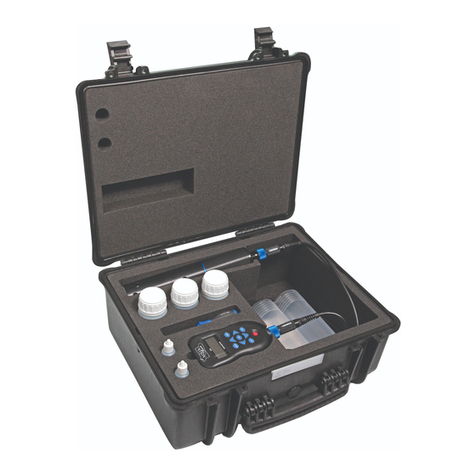
Aquaread LeveLine Series User manual

Instruction Manual
for the
LeveLine®
Range of Level and Baro Probes
and associated
LeveLine® Meter, Utilities & Accessories
Document No. 10401-01026
Revision: D
Date: December 10, 2019
Aquaread® Ltd
Bridge House
Northdown Industrial Park
Broadstairs
Kent
CT10 3JP
ENGL ND
Phone: +44 1843 600 030
www.aquaread.com

LeveLine® Instruction Manual 10401-01026 Rev D
PROPRIETARY NOTICE
The information disclosed within this document or separately supplied in furtherance of this document includes
proprietary rights of Aquaread® Ltd. Neither this document nor the information disclosed herein or of a
supplementary nature shall be reproduced or transferred to other documents or used for any other purposes,
except as specifically authorised in writing by Aquaread® Ltd. Copyright 013 - 019 Aquaread® Ltd. All rights
reserved.
SOFTWARE LICENCE AGREEMENT
By using the LeveLine® Pro es, the associated Meter and PC ased software
(LeveLink™), you agree to e ound y the terms and conditions of the following
software licence agreement. Please read this agreement carefully.
Aquaread® Ltd grants you a limited license to use the software embedded in the devices (the “Software”) in
binary executable form in the normal operation of the products. Title, ownership rights and intellectual
property rights in and to the Software remain in Aquaread® Ltd.
You acknowledge that the Software is the property of Aquaread® Ltd and is protected under British
copyright laws and international copyright treaties. You further acknowledge that the structure, organisation
and code of the Software are valuable trade secrets of Aquaread® Ltd.
You agree not to decompile, dissemble, modify, reverse assemble, reverse engineer or reduce to human
readable form the Software or any part thereof or create any derivative works based on the Software.
RECYCLING
Any product bearing this symbol must be handed over to an applicable collection point for the
recycling of electrical and electronic equipment. By ensuring this product is disposed of properly,
you will prevent possible adverse consequences for the environment which could be caused by
inappropriate waste handling.
Note: For return for recycling, please contact Aquaread® Ltd for instructions on how to return end-of-life
equipment, accessories, and all auxiliary items for proper disposal.
WARNING
Favourable indications made by this equipment do not guarantee water is safe for human or
animal consumption. This equipment can not detect the presence of harmful bacteria or toxins. If in
doubt, ALWAYS TREAT SUSPECT WATER PRIOR TO CONSUMPTION.
Limitations of Lia ility
Aquaread® Ltd and its affiliates specifically disclaim liability for any and all direct, indirect, special,
general, incidental, consequential, punitive or exemplary damages including, but not limited to, loss
of profits or revenue or anticipated profits or revenue or expenses incurred arising out of the use or
inability to use any Aquaread® product, miscalibration, miscalculation, loss of data or product failure,
even if Aquaread® Ltd and/or its affiliates has been advised of the possibility of such damages or
they are foreseeable or for claims by any third party. Notwithstanding the foregoing, in no event
shall Aquaread® Ltd and/or its affiliates aggregate liability arising under or in connection with
Aquaread® products, regardless of the number of events, occurrences, or claims giving rise to
liability, be in excess of the price paid by the purchaser for the Aquaread® product.
TRADEMARKS
Aquaread®, AquaPlus™, LeveLine®, LeveLine CTD® Aquapro e®, LeveLink™ and RapidCal™
are all trademarks of Aquaread® Ltd.
Microsoft®, Windows® and Excel® are trademarks of Microsoft Corporation
GOOGLE™ is a trademark of Google, Inc.
Aquaread ®
Ltd has no affiliation with Microsoft Corporation or Google, Inc.
© 2019 quaread® Ltd. www.aquaread.com Page 2 of 90

LeveLine® Instruction Manual 10401-01026 Rev D
Ta le of Contents
1. INTRODUCTION TO THE LEVELINE® PRODUCT RANGE...............................................................................7
1.1. WHAT DO THEY ALL DO?..............................................................................................................................................7
1.1.1. LeveLine® Loggers............................................................................................................................................7
1.1.2. LeveLine® Meter................................................................................................................................................7
1.1.3. LeveLine® QuickDeploy™ Key.........................................................................................................................8
1.2. LEVELINE® CABLING .....................................................................................................................................................8
1.2.1. Direct Connection of LeveLine® Logger to PC...........................................................................................8
1.2.2. Connection of LeveLine® Logger to PC vi n extension c ble.................................................................9
1.2.3. Connection of LeveLine® Logger to LeveLine® Meter...............................................................................9
1.2.4. Direct Connection of LeveLine® Meter to PC.............................................................................................9
1.2.5. Connection of LeveLine® Logger to telemetry device...............................................................................10
1.3. LEVELINE® BATTERY LIFE ...........................................................................................................................................10
1.3.1. Import nt Note Reg rding B ttery Life............................................................................................................10
1.4. LEVELINE-CTD® BATTERY LIFE ..................................................................................................................................11
1.4.1. Import nt Note Reg rding B ttery Life............................................................................................................11
1.5. LEVELINE® FACTORY CALIBRATION ...............................................................................................................................11
1.5.1. F ctory Re-c libr tion of Level nd Temper ture...........................................................................................11
1.5.2. Re-c libr tion of the Electric l Conductivity Cell...........................................................................................12
2. LEVELINK™ PC SOFTWARE...................................................................................................................................13
2.1. CABLE REQ IREMENTS...................................................................................................................................................13
2.2. DOWNLOADING LEVELINK™ PC SOFTWARE FROM THE AQ AREAD® WEBSITE .....................................................................13
2.3. SOFTWARE INSTALLATION...............................................................................................................................................13
2.4. DRIVER INSTALLATION...................................................................................................................................................13
2.5. STARTING LEVELINK™.................................................................................................................................................14
2.6. LEVELINE® SET P SCREEN OVERVIEW ...........................................................................................................................14
2.6.1. On Screen Help.................................................................................................................................................15
2.6.2. Connecting LeveLine® Probe to your PC.....................................................................................................15
2.6.3. Ch nging nd Upd ting the LeveLine® Logger's Settings..............................................................................16
2.6.4. Upd te Buttons.................................................................................................................................................16
2.6.5. PC Applic tion Setup........................................................................................................................................16
2.7. CALIBRATING THE ELECTRICAL COND CTIVITY CELL ON - CTD PROBE MODELS ..................................................................17
2.7.1. EC C libr tion St nd rds................................................................................................................................18
2.7.2. Recognising the EC Cell...................................................................................................................................18
2.7.3. EC C libr tion Technique................................................................................................................................18
2.7.4. EC Cell Const nt..............................................................................................................................................19
2.7.5. Frequency of EC C libr tion...........................................................................................................................19
2.8. LEVELINE® SET P IN DETAIL .......................................................................................................................................19
2.8.1. Checking Memory nd B ttery St tus (logging versions only)........................................................................20
2.8.2. Cle ring the LeveLine's Memory (logging versions only)................................................................................20
2.8.3. LeveLine® Clock Setup (logging versions only)..............................................................................................20
2.8.4. LeveLine® Site Ident Setup (logging versions only)........................................................................................20
2.8.5. LeveLine® Deployment Position Setup (logging versions only)......................................................................21
2.8.6. LeveLine® Scheduled Logging St rt, Logging Interv l nd Dur tion Setup..................................................23
2.8.7. LeveLine® M nu l Logging St rt, Logging Interv l nd Dur tion Setup......................................................25
2.8.8. M nu l Logging St rt using LeveLink™.........................................................................................................26
2.8.9. Overriding Scheduled Logging St rt.............................................................................................................26
2.8.10. LeveLine® Event Logging Setup....................................................................................................................26
2.9. PREPARING TO PLOAD LOGGED DATA FROM A LEVELINE® LOGGER OR LEVELINE® METER ..............................................27
2.9.1. Connecting LeveLine® Logger to your PC...................................................................................................27
2.9.2. Connecting LeveLine® Meter to your PC.....................................................................................................28
2.10. PLOADING LOGGED DATA FROM A LEVELINE® LOGGER OR LEVELINE® METER .............................................................28
2.10.1. Viewing Logged D t .....................................................................................................................................31
2.10.2. Zooming In nd Out........................................................................................................................................31
2.10.3. S ving Logged D t .......................................................................................................................................32
2.10.4. Retrieving Logged D t Files.........................................................................................................................33
2.10.5. Exporting Logged D t to Spre dsheet.......................................................................................................33
2.10.6. Exporting Logged D t to Google™ E rth Files..........................................................................................33
2.10.7. Viewing Files in Google™ E rth...................................................................................................................33
2.11. LEVEL DATA CORRECTION ...........................................................................................................................................35
© 2019 quaread® Ltd. www.aquaread.com Page 3 of 90

LeveLine® Instruction Manual 10401-01026 Rev D
2.11.1. Lo ding Logged D t .....................................................................................................................................35
2.11.2. Selecting Corrections.....................................................................................................................................35
2.11.3. B ro Correction Overview.............................................................................................................................36
2.11.4. W ter Density Correction...............................................................................................................................36
2.11.5. Offset Correction............................................................................................................................................37
2.11.6. D t Aver ging...............................................................................................................................................37
2.11.7. Applying Corrections......................................................................................................................................38
2.11.8. Applying Multiple Corrections.......................................................................................................................38
2.11.9. Exporting Corrected D t ..............................................................................................................................38
3. LEVELINE® DEPLOYMENT.....................................................................................................................................39
3.1. IDENTIFYING THE LEVELINE® TYPE AND DEPTH RATING ...................................................................................................39
3.2. DEPLOYING THE ABS AND BARO VERSIONS....................................................................................................................39
3.2.1. Deployment in Open W ter..............................................................................................................................40
3.2.2. Choice of Suspension C ble.............................................................................................................................40
3.2.3. Deployment Depth............................................................................................................................................40
3.2.4. Deploying the ABS Logger...............................................................................................................................40
3.2.5. Deploying the G uge (Vented) Version............................................................................................................40
3.2.6. Fitting Desicc nt Housing nd C rtridge.....................................................................................................41
3.2.7. Regener ting Desicc nt....................................................................................................................................43
3.2.8. G uge (Vented) Version Zero Offset................................................................................................................43
3.2.9. Recording the Deployment Offset.....................................................................................................................43
3.3. DEPLOYING THE BARO LOGGER......................................................................................................................................44
3.4. SING THE LEVELINE® Q ICKDEPLOY™ KEY ................................................................................................................44
3.4.1. Setup Prior To Deployment with QuickDeploy™ Key..................................................................................44
3.4.2. Deploying the LeveLine® Using the QuickDeploy™ Key...............................................................................44
3.4.3. Using the QuickDeploy™ Key After Deployment............................................................................................45
3.4.4. QuickDeploy™ Key B ttery Repl cement.......................................................................................................45
3.5. DEPLOYING THE LEVELINE® MINI AND MINI-CTD .........................................................................................................45
4. LEVELINE® METER...................................................................................................................................................4
4.1. THE LEVELINE® METER AND THE ENVIRONMENT .............................................................................................................46
4.2. METER BATTERY INSTALLATION AND CARE ......................................................................................................................46
4.2.1. Choice of B ttery Type.....................................................................................................................................46
4.2.2. B ttery Life.......................................................................................................................................................46
4.2.3. B ttery Ch rging..............................................................................................................................................46
4.2.4. B ttery Condition Icon.....................................................................................................................................47
4.2.5. B ttery S ver Functions...................................................................................................................................47
4.3. OVERVIEW OF THE OPERATING SYSTEM............................................................................................................................47
4.4. INITIAL SWITCH ON AND CLOCK SET P ...........................................................................................................................47
4.5. CONNECTING TO A LEVELINE® LEVEL OR BARO LOGGING PROBE ......................................................................................48
4.5.1. Connecting the C ble to the Meter...................................................................................................................48
4.5.2. Connecting the C ble to Logger....................................................................................................................48
4.6. TAKING MEAS REMENTS................................................................................................................................................49
4.7. WHAT DOES IT ALL MEAN?.........................................................................................................................................50
4.8. GPS RECEPTION...........................................................................................................................................................50
4.9. METER SET P..............................................................................................................................................................51
4.9.1. Setting Units of Me surement...........................................................................................................................51
4.9.2. Setting the Meter Time & D te.........................................................................................................................51
4.9.3. Setting the EC Correction.................................................................................................................................52
4.9.4. Setting S linity..................................................................................................................................................52
4.10. CALIBRATING THE ELECTRICAL COND CTIVITY CELL ON - CTD PROBE MODELS ................................................................53
4.10.1. EC C libr tion St nd rds..............................................................................................................................53
4.10.2. Recognising the EC Cell.................................................................................................................................53
4.10.3. EC C libr tion Technique..............................................................................................................................53
4.10.4. EC Cell Const nt............................................................................................................................................54
4.10.5. Frequency of EC C libr tion.........................................................................................................................54
4.11. PROBE SET P (APPLICABLE TO LOGGING VERSIONS ONLY)..................................................................................................55
4.11.1. Probe Clock Setup..........................................................................................................................................55
4.11.2. Logging R te Setup.........................................................................................................................................55
4.11.3. Event Logging Setup.......................................................................................................................................56
4.11.4. Deployment Site Ident Setup...........................................................................................................................57
4.11.5. Probe Deployment Position Setup..................................................................................................................58
© 2019 quaread® Ltd. www.aquaread.com Page 4 of 90

LeveLine® Instruction Manual 10401-01026 Rev D
4.11.6. Logging St rt nd Dur tion Setup..................................................................................................................58
4.11.7. M nu l Logging St rt nd Stop using the Meter...........................................................................................59
4.12. PLOADING LOGGED DATA FROM THE PROBE.................................................................................................................60
4.13. DOWNLOADING LOGGED DATA FROM THE METER TO A PC..............................................................................................61
4.14. MEMORY TILITIES.....................................................................................................................................................63
5. CLEANING AND MAINTENANCE........................................................................................................................... 4
5.1. CLEANING THE PRESS RE SENSOR...................................................................................................................................64
5.2. CLEANING THE EC CELL (-CTD VERSION ONLY).............................................................................................................64
. CONNECTING TO THIRD PARTY TELEMETRY AND LOGGING DEVICES............................................... 5
6.1. INTROD CTION..............................................................................................................................................................65
6.2. CONNECTIONS...............................................................................................................................................................65
SDI-12 DIGITAL INTERFACE
6.3. SDI-12 DIGITAL INTERFACE WIRING ..............................................................................................................................66
6.4. SDI-12 DATA COMM NICATION PROTOCOL.....................................................................................................................67
6.5. SDI-12 DATA PACKET FORMATS...................................................................................................................................67
6.5.1. Acknowledge Active..........................................................................................................................................67
6.5.2. Address Query..................................................................................................................................................68
6.5.3. Ch nge Address................................................................................................................................................68
6.5.4. Send Identific tion............................................................................................................................................68
6.5.5. St rt Me surement............................................................................................................................................68
6.5.6. Addition l Me surements.................................................................................................................................69
6.5.7. St rt Me surement nd Request CRC..............................................................................................................69
6.5.8. Addition l Me surements nd Request CRC....................................................................................................69
6.5.9. St rt Concurrent Me surement........................................................................................................................70
6.5.10. Addition l Concurrent Me surements............................................................................................................70
6.5.11. St rt Concurrent Me surement nd Request CRC.........................................................................................70
6.5.12. Addition l Concurrent Me surements nd Request CRC..............................................................................71
6.5.13. St rt Verific tion............................................................................................................................................71
6.5.14. Service Request...............................................................................................................................................71
6.5.15. Send D t .......................................................................................................................................................71
6.5.16. Continuous Me surements.............................................................................................................................72
6.5.17. Continuous Me surements nd Request CRC................................................................................................72
6.6. SDI-12 DEVICE ADDRESS.............................................................................................................................................72
6.7. SDI-12 NIT IDENTIFICATION........................................................................................................................................72
6.8. SDI-12 MEAS REMENT COMMANDS...............................................................................................................................73
6.9. SDI-12 CYCLIC RED NDANCY CHECK............................................................................................................................75
MODBUS DIGITAL INTERFACE
6.10. MODB S COMM NICATION PROTOCOL.......................................................................................................................76
6.11. MODB S DIGITAL INTERFACE WIRING ......................................................................................................................76
6.12. MODB S DATA FRAME FORMAT..............................................................................................................................77
6.13. MODB S COMM NICATION SEQ ENCE.......................................................................................................................77
6.14. MODB S DATA PACKET FORMAT.............................................................................................................................77
6.14.1. Exception Responses.......................................................................................................................................78
6.14.2. Re d Holding Registers..................................................................................................................................78
6.14.3. Re d Input Registers.......................................................................................................................................79
6.14.4. Write Holding Register...................................................................................................................................79
6.14.5. Write Holding Registers.................................................................................................................................80
6.14.6. Report Sl ve ID..............................................................................................................................................80
6.15. MODB S REGISTER MAP.........................................................................................................................................81
6.15.1. Sl ve Address..................................................................................................................................................82
6.15.2. Modbus Mode.................................................................................................................................................82
6.15.3. Seri l Communic tion Speed..........................................................................................................................82
6.15.4. Seri l Communic tion P rity.........................................................................................................................83
6.15.5. Input Registers................................................................................................................................................83
6.16. MODB S CYCLIC RED NDANCY CHECK....................................................................................................................83
.17. DEPTH CALCULATION FOR THIRD PARTY DEVICES.......................................................................................................84
6.17.1. W ter Density C lcul tion.............................................................................................................................84
6.17.2. Depth C lcul tion...........................................................................................................................................84
© 2019 quaread® Ltd. www.aquaread.com Page 5 of 90

LeveLine® Instruction Manual 10401-01026 Rev D
7. LIMITED WARRANTY...............................................................................................................................................85
7.1. CLEANING PRIOR TO RET RN.........................................................................................................................................85
7.2. DECONTAMINATION CERTIFICATE.....................................................................................................................................86
8. TROUBLESHOOTING.................................................................................................................................................87
8.1. TRO BLESHOOTING LEVELINK™....................................................................................................................................88
9. DECLARATION OF CONFORMITY........................................................................................................................88
10. TECHNICAL SPECIFICATION...............................................................................................................................89
© 2019 quaread® Ltd. www.aquaread.com Page 6 of 90

LeveLine® Instruction Manual 10401-01026 Rev D
1. Introduction to the LeveLine® Product Range
This manual covers the setup, operation and maintenance of the following equipment and
software:
•LeveLine® (Level & temperature logger)
•LeveLine-CTD® (Level, temperature, conductivity & salinity logger)
•LeveLine® Baro™ (Barometric pressure logger)
•LeveLine® Mini™ (SDI-1 /Modbus level & temperature transducer)
•LeveLine® Mini-CTD™ (SDI-1 /Modbus Level, temperature, conductivity & salinity transducer)
•LeveLine® Meter (Setup / Live data / Data upload accessory)
•LeveLine® QuickDeploy™ Key (Deployment accessory)
•LeveLink™ PC software (Setup / Calibration / Live data / Data analysis utility)
1.1. What Do They All Do?
1.1.1. LeveLine® Loggers
The Aquaread® LeveLine® range of Level and Baro Logging Probes are self-contained
data-logging device that record pressure and temperature continuously during their
deployment. They feature highly accurate pressure and temperature sensors, a
microprocessor and a large memory, which are powered for up to 10 years by an internal
3.6V lithium battery. The -CTD model also records electrical conductivity.
The LeveLine® Baro version is designed for use above the waterline to record barometric
pressure data. This version offers a maximum logging rate of once per minute with a
storage capacity of 150,000 records.
The LeveLine® Mini™ Probes do not have any logging ability. These are designed to output
live pressure and temperature data to a third party logging device using industry standard
interfaces. The -CTD version also outputs live electrical conductivity and salinity data.
The entire LeveLine® range is constructed from ultra-rugged titanium and can be deployed
for long periods in hostile environments.
1.1.2. LeveLine® Meter
The LeveLine® Meter is a waterproof (IP67 ) hand-held device designed to allow full on-site
logger setup, data retrieval / storage and live monitoring, which is particularly ideal for
pumping operations.
A built-in GPS receiver allows the user to embed GPS coordinates (including altitude) in the
Logger’s memory as it is deployed so that it appears as part of the dataset upon retrieval.
A built-in barometric air pressure sensor allows live barometric level correction. The meter
also has the facility to add a salinity value for live water density compensation.
Data from up to 300 Loggers can be retrieved onto the Meter on site then transferred onto a
PC for analysis at a later date.
When connected to a -CTD model Probe, the electrical conductivity sensor can also be
easily calibrated.
© 2019 quaread® Ltd. www.aquaread.com Page 7 of 90

LeveLine® Instruction Manual 10401-01026 Rev D
1.1.3. LeveLine® QuickDeploy™ Key
The QuickDeploy™ Key is a simple plug-in device which allows a pre-programmed logging
scheme to be started at the exact instant of deployment. It also embeds a zero depth
reference marker in the logged data in order to allow absolute depth measurement from the
start and carries out an instant check on the battery and memory levels.
This means loggers can be set up with the desired logging frequencies but no start date &
time, then stored on the shelf for any given time period. The user can then take the loggers
as required and initiate logging using the QuickDeploy™ Key as they deploy each
instrument in the field.
This ensures there is no data lost if the loggers are deployed early and there is no memory
and battery wasted if the loggers are deployed late.
1.2. LeveLine® Ca ling
A number of cables and adaptors are available to allow for various connection
permutations. The following are some of the most popular and useful combinations.
1.2.1. Direct Connection of a LeveLine® Logger to a PC
The LeveLine® PC Kit (Part No. LL-PC-KIT) shown above allows direct connection of a
LeveLine® Logger to a PC via a USB port.
The clear USB connector housing contains a red and a green LED. Each time the PC
sends data to the LeveLine®, the red LED will flash. Each time the LeveLine® returns data,
the green LED will flash.
This is a very useful tool for fault finding. If you experience communications problems,
looking at the LEDs will tell you if the problem is with the PC not sending data or the
LeveLine® not responding.
If you do not see any flashing LEDs, check the USB Cable drivers are correctly installed.
See section .4
© 2019 quaread® Ltd. www.aquaread.com Page 8 of 90

LeveLine® Instruction Manual 10401-01026 Rev D
1.2.2. Connection of a LeveLine® Logger to a PC via an extension ca le
This option can be used to setup the Logger, read live data or upload logged data whilst the
LeveLine® Logger is installed.
The LeveLine® USB to Extension Adaptor (Part No. LL-USB-EXT-AD) shown above
provides an interface between the LL-PC-KIT and any length of LeveLine® extension cable
(Part No. EXT-LL-XM).
1.2.3. Connection of a LeveLine® Logger to a LeveLine® Meter
This option can be used to setup the Logger, read live data or upload logged data whilst the
LeveLine® Logger is installed. For this, a LeveLine® extension cable (Part No. EXT-LL-XM)
is required.
1.2.4. Direct Connection of a LeveLine® Meter to a PC
This option can be used to retrieve data from a LeveLine® Meter, that has been previously
uploaded to that Meter from a LeveLine® Logger.
For this, a LeveLine® PC kit is required and a LeveLine® Meter to USB adaptor (Part No.
LLM-USB-AD). This adaptor is supplied as standard with the LeveLine® Meter.
© 2019 quaread® Ltd. www.aquaread.com Page 9 of 90

LeveLine® Instruction Manual 10401-01026 Rev D
1.2.5. Connection of a LeveLine® Logger to a telemetry device
This option can be used to obtain live data from a LeveLine® Logger via a telemetry device.
For this, a LeveLine® extension cable (Part No. EXT-LL-XM) is required along with a
LeveLine® Extension to Telemetry Adaptor (Part No. LL-EXT-TEL-AD) as shown above.
For full details of the Telemetry Adaptor wiring and data protocols, refer to section 6
1.3. LeveLine® Battery Life
All LeveLine® Loggers run from a single, dealer replaceable 3.6V Lithium-thionyl Chloride
(Li-SOCL ) battery.
The table below shows typical battery life of the standard LeveLine® Loggers at various
logging/event checking rates at 5°C. Higher temperatures can increase the rate of self
discharge and hence reduce the figures shown.
Logging / Event Checking Interval Expected Battery Life
0.1 Sec 18 Days
0.5 Sec 3 Days
1.0 Sec 60 Days
15.0 Sec . 5 Years
1 Min 7.5 Years
> Min > 10 Years
The table above naturally assumes that the Logger's memory would be cleared down each
time it becomes full, otherwise, the Logger would simply stop logging when the memory
was full and the battery would then be subject to a quiescent discharge only.
1.3.1. Important Note Regarding Battery Life
If you set a long logging interval but a very short event checking interval, the battery life
should be estimated on the event checking interval rate. Even though the logger will not log
data every time an event is checked, it will take a reading and hence will use the same
amount of battery power as a logged data point. Always choose the longest logging / event
checking interval that you can for your application in order to prolong the battery life.
© 2019 quaread® Ltd. www.aquaread.com Page 10 of 90

LeveLine® Instruction Manual 10401-01026 Rev D
1.4. LeveLine-CTD® Battery Life
All LeveLine-CTD® Loggers run from a single, dealer replaceable 3.6V Lithium-thionyl
Chloride (Li-SOCL ) battery.
The table below shows typical battery life of the LeveLine-CTD® Loggers at various
logging/event checking rates at 5°C. Higher temperatures can increase the rate of self
discharge and hence reduce the figures shown.
Logging / Event Checking Interval Expected Battery Life
1 Sec 6 Days
15 Sec 90 Days
1 Min 1 Year
5 Min 5 Years
10 Min 10 Years
> 10 Min > 10 Years
1.4.1. Important Note Regarding Battery Life
If you set a long logging interval but a very short event checking interval, the battery life
should be estimated on the event checking interval rate. Even though the logger will not
log data every time an event is checked, it will take a reading and hence will use the same
amount of battery power as a logged data point. Always choose the longest logging / event
checking interval that you can for your application in order to prolong the battery life.
1.5. LeveLine® Factory Cali ration
All LeveLine® water level Loggers are factory calibrated at five separate pressure points
across their pressure range, at two temperatures, 5°C and 5°C. In addition, the -CTD
versions are also calibrated at a single electrical conductivity point.
All LeveLine® Baro Loggers are factory calibrated at three separate pressure points across
their pressure range, at two temperatures, 5°C and 5°C.
The data produced by this calibration procedure is used to construct a three dimensional
calibration curve (surface), which is stored in each Probe's memory and subsequently used
to automatically correct temperature and pressure readings prior to output.
The date at which your LeveLine® Logger was last calibrated is shown in the 'LeveLine
Status' box on the Setup tab of the LeveLink™ PC software.
1.5.1. Factory Re-cali ration of Level and Temperature
The accuracy of LeveLine® Loggers can be adversely affected by physical damage or
abuse, improper care and handling, exceeding operating pressure and temperature limits,
lightning strikes and similar power surges, as well as normal drift in the device’s electronic
components.
Excluding physical damage, the need for factory recalibration is dependent upon the
amount of drift you are willing to tolerate.
© 2019 quaread® Ltd. www.aquaread.com Page 11 of 90

LeveLine® Instruction Manual 10401-01026 Rev D
For optimum performance, factory re-calibration is recommended every 1 -18 months.
1.5.2. Re-cali ration of the Electrical Conductivity Cell
The electrical conductivity (EC) cell on the -CTD versions can be user calibrated at any
time and at any value between 100µS/cm and 99,999µS/cm.
Re-calibration of the EC Cell can be carried out by using either the LeveLink™ PC software
(see: Calibrating the Electrical Conductivity Cell on - CTD Probe Models) or the LeveLine®
Meter (see: Calibrating the Electrical Conductivity Cell on - CTD Probe Models).
© 2019 quaread® Ltd. www.aquaread.com Page 12 of 90

LeveLine® Instruction Manual 10401-01026 Rev D
2. LeveLink™ PC Software
LeveLink™ PC software allows full setup and management of the LeveLine® family of
Loggers, retrieval, storage, analysis and post correction of logged data from both the
Loggers and the LeveLine® Meter, and the generation of spreadsheet, graphic and
Google™ Earth files. In addition, LeveLink™ allows calibration of the EC function of the
-CTD model Probes.
LeveLink™ is designed to run under Microsoft® Windows® Vista® or later on a stand-alone
PC with a minimum screen resolution of 1 80 x 960 and an available USB .0 socket. Your
PC must have Windows® .NET Framework version 4.00 or higher installed. If you are
running an earlier version, you will be prompted to download and install a later version of
.NET Framework from the Microsoft® website when you first run LeveLink™ setup. Please
note, Window® XP® and earlier version are no longer fully supported.
2.1. Ca le Requirements
In order to communicate directly with a LeveLine® logger or meter, you will require a
LeveLine® PC cable kit. Part number: LL-PC-KIT.
If you wish to connect a PC or Laptop to a LeveLine® logger which is already deployed on
an extension cable, you will require an additional USB cable to extension cable adapter.
Part number: LL-USB-EX-AD. See section 1. for full details of LeveLine® cabling options.
2.2. Downloading LeveLink™ PC Software from the Aquaread® we site
The LeveLink™ PC Software is available for download using the following link:
http://www.aquaread.com/software-downloads
From the Aquaread® Downloads page, select 'LeveLink-LeveLine Utility'. The software will
be downloaded as a .ZIP file.
2.3. Software Installation
Unzip the downloaded .ZIP file into a temporary directory . Browse the temporary directory
and click on ‘setup.exe’. You will be given the usual Windows® security warnings. Allow the
software to install. Once installed, LeveLink™ will run automatically.
To communicate with the LeveLine® Probe or Meter, two further software ‘drivers’ need to
be installed. These are the 'LeveLine USB Ca le' driver and a 'USB Serial Port' driver.
2.4. Driver Installation
Connect the LeveLine® USB interface cable to your PC. You do not need a LeveLine®
Logger connected at this point. The ‘Found New Hardware’ wizard on your PC should
activate automatically.
Different versions of Windows® react to plugging USB devices in differently. Earlier versions
will give you the option to 'locate and install driver software'. If this happens, direct
Windows® to your temporary directory containing the unzipped download.
If your version of Windows® tries to search the Internet or 'Windows Update' for the drivers,
that is OK, but it might take some time. If this occurs, you can stop the search and direct
Windows® to your temporary directory.
© 2019 quaread® Ltd. www.aquaread.com Page 13 of 90

LeveLine® Instruction Manual 10401-01026 Rev D
After successful driver installation, the following message should be displayed.
The USB Serial Port number (COM10 in the above example) may be different, but that is fine
provided it shows ‘Ready to use’. If the drivers do not install properly, refer to the Troubleshooting
LeveLink™ section.
2.5. Starting LeveLink™
Select ►Aquaread then ►LeveLink™ from your Programs menu. After an introductory
splash-screen has been displayed, the LeveLine® Setup screen will appear:
If you are using a laptop or notebook with a small screen, the window can be resized by
dragging the bottom right hand corner.
2.6. LeveLine® Setup Screen Overview
The LeveLine® Setup screen allows you to setup the following parameters:
•The LeveLine® Logger's real time clock
•A unique name (ident) for the LeveLine® Logger
© 2019 quaread® Ltd. www.aquaread.com Page 14 of 90

LeveLine® Instruction Manual 10401-01026 Rev D
•The LeveLine® Logger's deployment position and altitude
•The LeveLine® Logger's logging start date and duration
•The LeveLine® Logger's logging rate
•The LeveLine® Logger's event logging criteria
•The LeveLink™ PC application's preferences
In addition, this screen allows you to view live data from a connected LeveLine® Logger or
LeveLine® Mini and to clear the Logger's memory. When used with a -CTD type LeveLine®,
the electrical conductivity cell (EC) can be calibrated.
Before attempting to adjust any of the parameters on the screen, connect a LeveLine®
Logger.
2.6.1. On Screen Help
Help has been provided in this software in the form of ‘Tool Tips’. If you want to know what
a control button does or what a data box displays, simply move your mouse pointer over
the item in question. A Tool Tip will appear after a few seconds to give you more
information.
2.6.2. Connecting a LeveLine® Pro e to your PC
To connect a LeveLine® Probe directly to your PC, the LeveLine® PC Kit (Part No. LL-PC-
KIT) described in section 1. should be used. Connect one end of the cable to the
LeveLine® Probe, aligning it as shown below, and the other end to a spare USB port on
your PC.
If you wish to setup or retrieve data from a LeveLine® Logger whilst it is in-service, in a bore
hole for instance, an extension lead and USB adapter will be required. See section 1. . for
further details.
Once Windows® has recognised the device, click on the 'Connect to LeveLine®' button
located just below the Setup Instructions. The PC will communicate with the LeveLine®
Probe and begin to display live data in the LeveLine® Data window.
In addition, the LeveLine® Status window will be populated with the following data uploaded
from the Logger:
•Serial number
•Firmware revision
•Depth rating
•Sensor type
•Last calibration date
•Last EC (conductivity) calibration date (-CTD Version only)
•The EC calibration standard last used (-CTD Version only)
•The EC cell constant (-CTD Version only)
•Number of records stored
•Memory capacity remaining
© 2019 quaread® Ltd. www.aquaread.com Page 15 of 90

LeveLine® Instruction Manual 10401-01026 Rev D
•Battery capacity in % remaining
On the right hand side of the screen, the settings currently held in the LeveLine® Logger will
be displayed. Please note, when connected to a LeveLine® Mini, these settings are
irrelevant because the Mini Probes do not have any logging facility or a real-time clock.
2.6.3. Changing and Updating the LeveLine® Logger's Settings
The window located on the right hand side of the screen labelled 'LeveLine Settings' will
automatically be populated with data from the attached Logger.
The window located down the centre of the PC screen labelled 'User Settings Input' allows
you to alter any of the individual settings. For example, to alter the Logger's ident, input the
revised details in the 'Site Ident' box (which is within the 'Setup Ident and Deployment
Position' window) then click on the 'Update Ident' button. This will transfer the revised ident
to the Logger and the 'Site Ident' box in the 'LeveLine Settings' window will be updated.
2.6.4. Update Buttons
You will notice that adjacent to each block of settings, there is a corresponding 'Update'
button. If the data stored in the Logger is the same as the data displayed within the 'User
Settings Input' boxes, the associated update button will be grey.
If the data stored in the Logger differs from the data displayed within the 'User Settings
Input' boxes, the associated update button will be red as shown below.
This is to remind you to transfer settings that have been changed.
If any of the Update buttons are red, the PC software will prompt you to update the settings
in the Logger if you try to disconnect the Logger, leave the current screen or close the
program.
2.6.5. PC Application Setup
The first thing to do when using LeveLink™ is to setup your personal preferences. These
are selectable in the PC Application Setup window.
The selections made here will be used throughout the PC application for all data display
© 2019 quaread® Ltd. www.aquaread.com Page 16 of 90

LeveLine® Instruction Manual 10401-01026 Rev D
and file outputs.
You may choose to display Pressure in any one of the following units:
•mbar (millibar)
•bar
•mmHg (millimetres of mercury)
•inHg (inches of mercury)
•cm water
•inches water
•kPa
•psi
You may choose to display Level in any one of the following units:
•meters
•centimetres
•millimetres
•feet
•inches
You may choose to display Temperature in either centigrade or Fahrenheit.
When using a -CTD version, you may choose to display electrical conductivity (EC)
referenced (corrected) to 5°C, 0°C or absolute (ABS). Absolute EC does not have any
temperature correction applied.
2.7. Cali rating the Electrical Conductivity Cell on - CTD Pro e Models
When connected to a – CTD Probe, the dedicated EC calibration boxes will be populated
and the Calibrate EC button will be enabled.
© 2019 quaread® Ltd. www.aquaread.com Page 17 of 90

LeveLine® Instruction Manual 10401-01026 Rev D
In the example above, it can be seen that the EC cell was last calibrated on 04/07/17 using
a calibration standard of 570µS/cm, and the resultant cell constant was 1.43.
2.7.1. EC Cali ration Standards
EC calibration is always carried out at a single point. There is a choice of two Aquaread®
calibration standards, or you can use any third party calibration standard value between
100µS/cm and 99,999µS/cm.
The Aquaread® standards are: Aquaread® RapidCal™ (EC value 570µS/cm at 5°C) for
general use, and Aquaread® SC-35 (EC value 53,065µS/cm at 5°C), which is specifically
for use when measuring EC and salinity in sea water.
The calibration solution value you use to calibrate EC should always be chosen to be as
near to the readings you expect to see in the field as possible. If you are not sure what
values to expect, RapidCal™ is a good choice as this will give reasonably accurate
readings across a wide range of EC values.
For best results, calibrate as close to 5ºC as possible. The probe will compensate for
temperature variation in the Calibration Standard during calibration.
2.7.2. Recognising the EC Cell
The -CTD Probes all have an elongated nose sleeve covering the EC cell contacts.
The lack plastic nose sleeve (shown removed on the right of the photo) forms an
integral, working part of the Pro e’s EC measurement system, and MUST e fitted
during cali ration and measurement for correct operation.
2.7.3. EC Cali ration Technique
1. Remove the nose sleeve from the Probe, wash the EC cell and the sleeve in
clean water, dry thoroughly, then replace the nose sleeve.
. Drop the Probe into a calibration bottle filled with EC Calibration Standard and
agitate to remove any air bubbles from inside the sleeve.
3. Ensure the liquid level is a ove the top row of holes in the nose sleeve.
Low liquid level will result in erroneous EC cali ration.
4. Connect the Probe to a PC running LeveLink™ and wait until the temperature
and EC measurements are completely stable.
5. Ensure the temperature of the solution is between 5ºC and 40ºC (41ºF -104ºF).
6. Enter the EC value of your calibration solution at 5ºC into the EC Cal Standard
box. If using Aquaread® RapidCal™, this value would be 570.
7. Click the 'Calibrate EC' button.
© 2019 quaread® Ltd. www.aquaread.com Page 18 of 90

LeveLine® Instruction Manual 10401-01026 Rev D
You will be prompted to confirm that you want to calibrate EC and to confirm that the
correct calibration standard has been entered.
If the software detects a problem, an error message will be displayed. Possible errors are:
•Temperature out of range. Must be between 5ºC and 40ºC (41ºF -104ºF).
•EC Calibration value out of range. Must be between 100µS/cm and 99,999µS/cm.
•Large differential between the selected calibration value and the actual EC reading,
which could indicate an incorrect calibration solution value
•Readings are unstable.
If any of these errors are displayed, take remedial action and try again.
If calibration is successful, a 'Calibration Complete' message will be displayed and the
dedicated EC calibration boxes will be refreshed with new values.
After calibration, rinse the Probe in fresh water.
2.7.4. EC Cell Constant
The EC cell constant is an indication of the health of the EC cell. Nominally, the EC cell
constant should be around 1. 5. This can vary with different calibration standard values
and calibration temperatures.
If the EC cell constant is reported above .00 or below 0.5, carefully clean the EC cell
contacts and the inside of the nose sleeve. Also check your calibration solution is fresh and
that you have input the quoted value (at 5ºC) during calibration.
2.7.5. Frequency of EC Cali ration
Ideally, EC calibration should be carried out regularly based upon the levels of soiling the
Probe experiences.
On a regular basis, thoroughly clean the inside of the nose sleeve and the four metal EC
contacts situated in the EC cell with a soft cloth or toothbrush and non-abrasive detergent.
Never use solvent or alcohol ased products to clean the EC cell. After cleaning,
replace the nose sleeve and re-calibrate.
2.8. LeveLine® Setup In Detail
The following sections provide detailed guidance for setting up a LeveLine® Logger and
assumes you have connected a LeveLine® Logger to your PC and connected to it by
clicking the 'Connect to LeveLine' button.
Once a LeveLine® is connected, the 'Disconnect LeveLine' button will become live and
should be used prior to disconnecting the LeveLine® unit.
© 2019 quaread® Ltd. www.aquaread.com Page 19 of 90

LeveLine® Instruction Manual 10401-01026 Rev D
2.8.1. Checking Memory and Battery Status (logging versions only)
This first thing to do prior to any setup is to check the LeveLine's memory and battery
status. This information is displayed in the 'LeveLine Status' window.
If you are planning a new deployment, ensure there is sufficient memory remaining for the
planned deployment duration at the planned logging rate. If the Logger runs out of memory,
it will stop logging. Also ensure the battery is in good condition.
If your attery is showing elow 10% capacity, it is strongly recommended that you
have it replaced y your dealer prior to any further deployment. See section 1.3 for
further details concerning battery life.
2.8.2. Clearing the LeveLine's Memory (logging versions only)
At the bottom of the LeveLine® Status window there is a 'Clear Memory' button. If you want
to clear the Logger's memory, click this button. Please use this feature with care. Once
the Logger's memory has een cleared, all level data stored in the Logger will e
permanently lost. The 'Clear Memory' button does not clear any of the user settings.
2.8.3. LeveLine® Clock Setup (logging versions only)
The clock setup windows are shown below.
The boxes within the window to the left labelled 'Setup Clock' show the current time and
date from your PC. You can override/change this time and date if you want to by directly
altering the values within the boxes.
The boxes within the window to the right labelled 'LeveLine Clock' shows the time and date
of the connected LeveLine® Logger.
If the two clocks disagree by more than a few minutes, the 'Update Clock' button will be
coloured red. To synchronise the clock in the LeveLine® Logger to the time shown in the
'Setup Clock' window, click the 'Update Clock' button.
2.8.4. LeveLine® Site Ident Setup (logging versions only)
The Site Ident windows are shown below bordered in red.
© 2019 quaread® Ltd. www.aquaread.com Page 20 of 90
This manual suits for next models
7
Table of contents
Other Aquaread Measuring Instrument manuals
Popular Measuring Instrument manuals by other brands

EPS
EPS Smart View DVA300 user manual

Morris Products
Morris Products 57085 manual

PCB Piezotronics
PCB Piezotronics IMI SENSORS 628F61 Installation and operating manual

Siemens
Siemens SITRANS LR 400 instruction manual

Velleman
Velleman AVM2050 user manual

Endress+Hauser
Endress+Hauser Solimotion FTR16 instructions