www.aquasafecanada.com | Maximus II Installation Instructions 05/13 | page 17page 16 | Maximus II Installation Instructions 05/13 | www.aquasafecanada.com
Figure 27
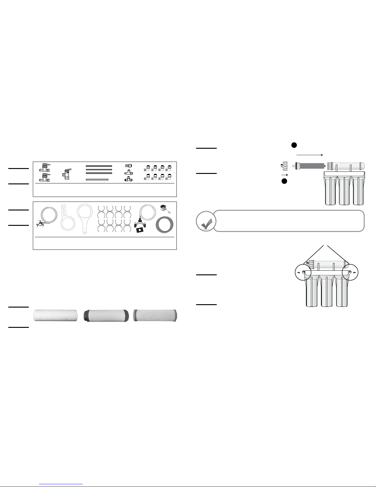
The PSI Meter
Figure 28
The TDS Meter
PLEASE NOTE: Position the manual shut o valve found before your oat valve to its OFF position
until your system has purged two completely lled volumes from the holding tank. Once this purge
has taken place, feel free to open the manual shut o valve to access the 0 ppm water for your aquatic
environment.
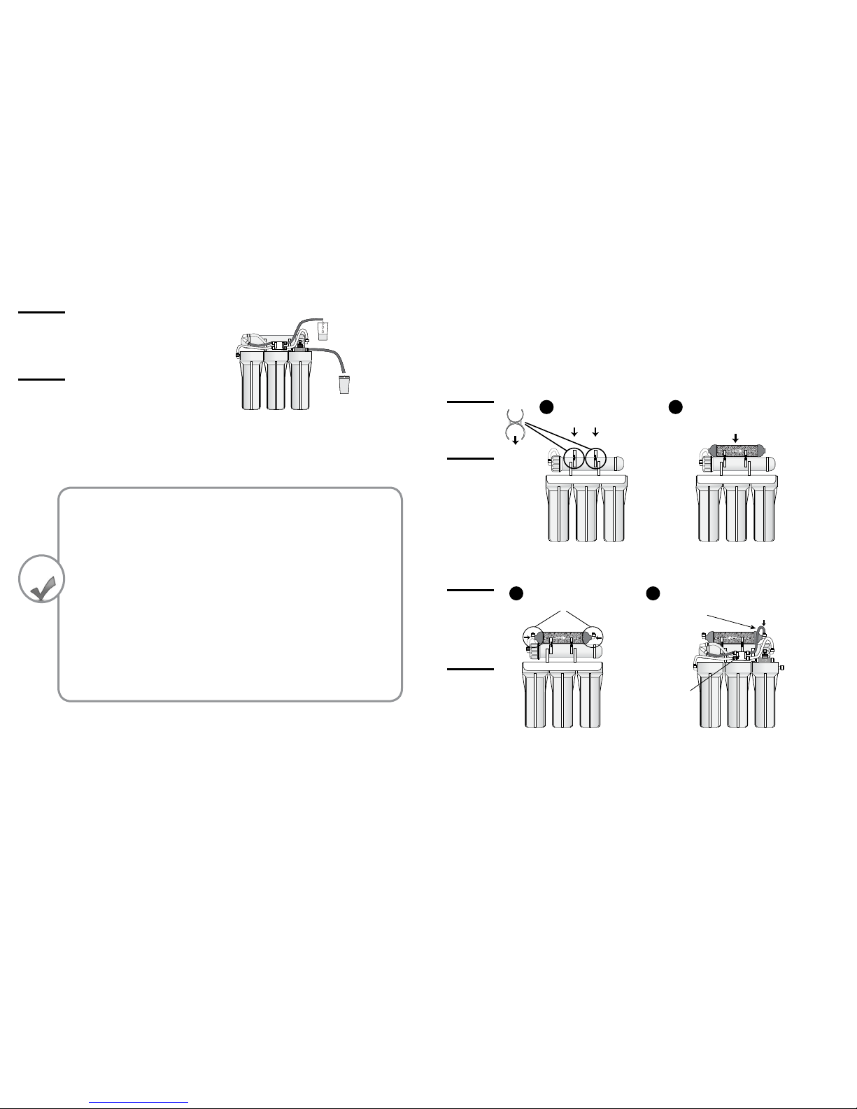
Check over all of the steps. Make sure all of your tubing is inserted rmly into the various quick con-
nect adaptors. You may now turn the manual shut-o valve found on your feed water line back to its
“ON” position.
Your 3.2 Gallon water storage tank will now begin lling and will take a maximum 2-3 hrs to ll to
capacity for its rst time and quicker thereafter. Once the tank has lled, empty all the water out of the
water holding tank and let rell. To empty all water from your storage tank once lled you simply need
to open your faucet until the output from the faucet turns to a fast drip or slow trickle. The R.O. Mem-
brane is lled with food grade preservative for quality assurance and the nal polishing lter and the
holding tank’s water bladder should be ushed out before consuming the water. Empty two full tanks
of water in order to ensure proper ushing of your entire system. After ushing two full tanks, you can
then drink and cook with the ultra puried water and use it for your aquarium.
After emptying your water storage tank twice, allow your system to pressurize. Monitor closely for po-
tential leaks. The nature of water is to nd the path of least resistance. Some initial small leaks are not
unheard of. If leaks do occur, depressurize your system (see Fig. 29) and see Aquasafe’s LEAKS PREVEN-
TION SECTION on the page 18 of this document.
GET A GOOD FLASHLIGHT AND CHECK OVER THE ENTIRE SYSTEM CAREFULLY WHEN COMPLETED TO
SPOT ANY POTENTIAL LEAKS.
¬Congratulations on completing the installation process. You may now start drinking the ultra puri-
ed drinking water you desire for the health and enjoyment of you, your loved ones and your aquatic
pets.
If you require further clarication after going through all of the information of these instructions,
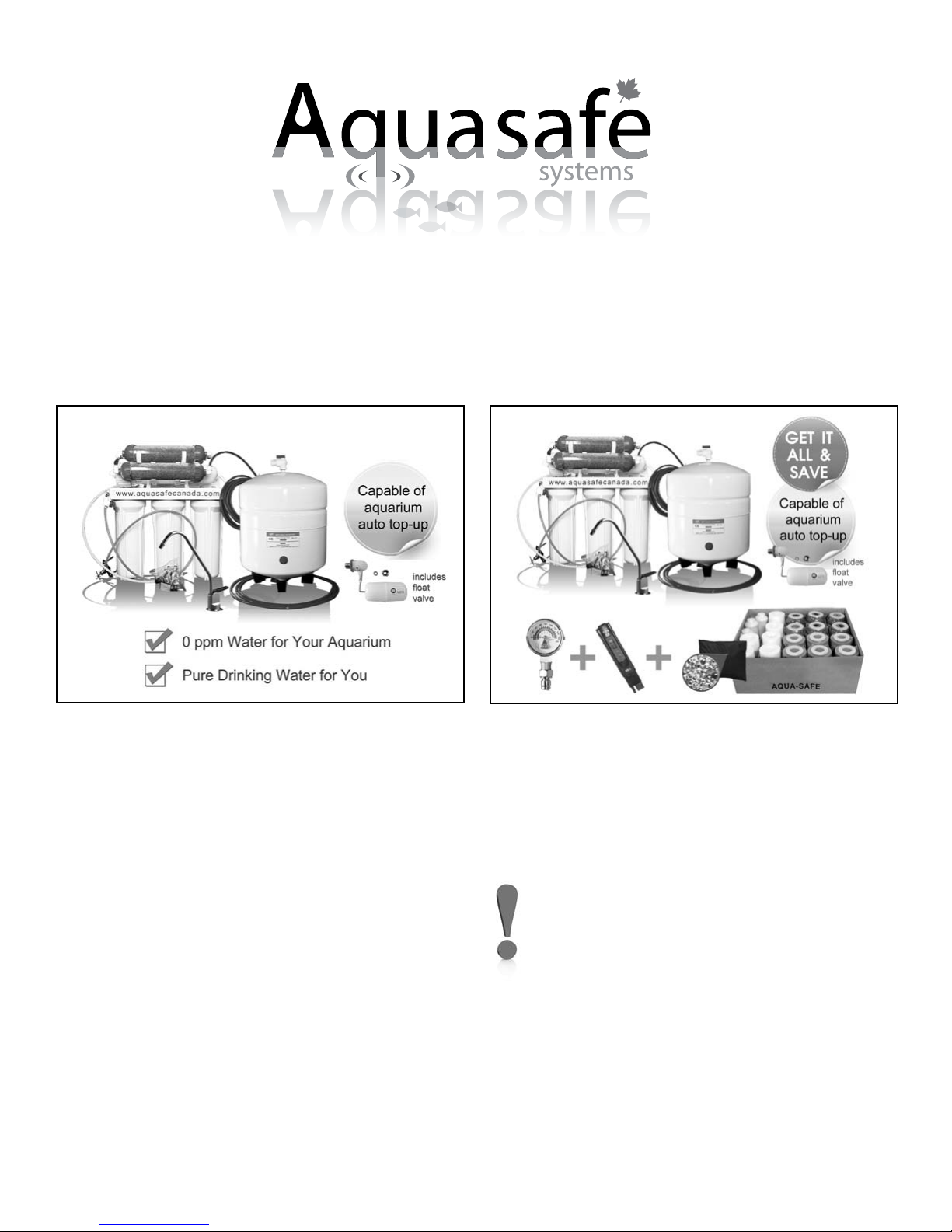
Extra information for the Aquarium II Dual COMBO
Where do I install the PSI Meter from my “COMBO” System?
If you have purchased the Aquarium II Dual System Combo, your system
came with a PSI Meter as seen in Figure 20. It is not necessary that the PSI
Meter be installed onto your system. The PSI Meter is provided as a conve-
nience to you as your entire system operates from water pressure. If need
be, the PSI Meter allows you to determine the water pressure at any point
on your Reverse Osmosis System which can make troubleshooting of any
potential problems on your system extremely easy. However, if you chose
to install the PSI Meter onto your system, there one area where installing
the PSI Meter on your system can be of use.
Option 1. If you are on a well water system, and you think you may have lower then 50 psi through-
out your home’s plumbing, a good place to install the PSI Meter is on the feed water line to
your Reverse Osmosis System (between the Manual Shut-O Valve and the inlet to the rst
pre-lter housing). This will allow for easy monitoring of the source water pressure enter-
ing your Reverse Osmosis System. Your system needs consistent pressure at 50 psi or above.
Typical well water systems will top out at 60 psi and bottom out at 40 psi. If this is the case
we highly recommend an automatic booster pump available on our website – found on the
General Parts & Accessories page.
Option 2. Installing the PSI Meter on the section of white tubing coming out of the third pre-lter
housing (that attaches to the auto shut o valve) will allow you to monitor the psi of the
OUTPUT water of the 3 pre-lters. When you install new pre-lters make a note of the psi
reading at this point. Write down the psi measurement with some permanent marker on a
piece of masking tape and stick it somewhere visible on the system. Now you can check to
see when the psi on this line drops to 15% below the initial reading you wrote down (0.85 x
initial psi reading). When this happens it is time to replace your pre-lters. You might want
to also write down on the masking tape the number you are watching for, 0.85 x initial psi
reading, to make it easier to determine the status of your system.
How do I use the TDS Meter from my “COMBO” System?
The TDS (Total Dissolved Solids) Meter of your system is ex-
tremely easy and intuitive to use and comes with its own set of
intructions, but here is a quick tutorial. First you will need to get
a small glass and rinse it of all dust or other particles. Now ll
the rinsed glass with the water for which you would like to de-
termine the TDS Reading (Total Dissolved Solids). Remove the
cap from the bottom of the TDS Meter and turn on the meter.
Now simply insert the portion of the TDS Meter that was cov-
ered by the cap into the glass of water. The number that shows
on the digital display is the ppm count (Parts Per Million) of TDS
(Total Dissolved Solids) in your water.
Note: Your TDS Meter has an auto shut o feature but try to remember to shut o the TDS Meter when
you are done testing your water to save on batteries !
How do I store my 24oz bag of extra D.I Resin Beads?
The DI Resin should be kept airtight, away from all sunlight and at room temperature. Your 24oz bag
of extra DI Resin Beads comes sealed airtight in a black 4ml bag. Once you open the sealed black bag
of extra resin, tape the bag so that it is once again airtight and store at room temperature. Only cut o
one corner of the bag so that resealing the bag is made easy. If stored properly, the shelf life of the DI
Resin is years.
How do I store my extra case of 21 (6 changes) pre-filters and post-filters?
Your case of 21 pre-lters and post-lters (6 full changes) can be stored in the same state in which they
arrived. Each lter comes wrapped in protective plastic. Store at room temperature. Shelf life is years.