GIR-3000 Instruction Manual
PAGE 9 of 44 Rev 2.0, 2012.8.21
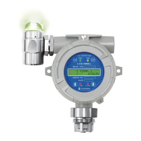
4.2. Components Description
No. Name of component Description
1 Housing Protecting sensors and PCB boards equipped inside the device housing
against environmental variations and shocks
2. Main PCB
Amplifying the output signal generated by sensor, converting it to
standard output of DC 4-20mA and transmitting converted signal. And
transmitting isolated RS-485 communication signal and alarm relay
contact signal. Also delivering data which will be shown in display panel.
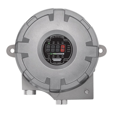
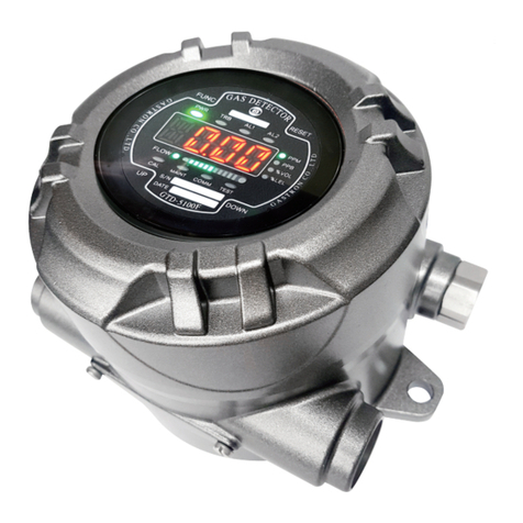
3. Display PCB Showing data sent by main PCB in LCD or OLED. Also displaying current
event status with using power lamp, alarm lamp and trouble lamp.
4. Power/Signal Terminal CN12 is composed of connection terminal for supplying DC18-24V
power and connection terminal for standard output (viso, +, mA, -).
5. Alarm signal Terminal CN8 is an alarm signal connection terminal which outputs relay contacts
of trouble, alarm1 and alarm 2.
6. RS-485 signal terminal CN3 is a signal connection terminal(A,B) for isolated RS-485
communication.
7. Sensor terminal C10 is a sensor connection terminal(RD, WH, BK, BE).
8. Power on/off switch
Turning on or off power of gas detector. The switch should be turned
off when cable work or A/S is performed. After finishing those works,
the switch can be on.
9. Power lamp When power switch turns on, this power lamp light will be on.
10. Trouble lamp When fault occurs in circuit or sensor sensitivity, the trouble lamp will
be on.
11. Alarm1 lamp The alarm1 lamp turns on when the measured value of gas becomes
over alarm1 level on gas leakage.
12. Alarm2 lamp The alarm2 lamp turns on when the measured value of gas becomes
over alarm2 level on gas leakage
13. Function switch
In order to set parameters, this function switch is used to allow the
device to enter program mode by touching it with magnet-bar for 2
seconds or more(Program mode, Calibration mode and Test mode are
also provided). The switch is also used to input and set data.
14. Reset switch
Reset switch can be used to cancel setting parameter or return back to
previous state by touching it once with magnet bar. (Each time it is
touched with magnet bar, the mode will be switched back to the
immediate previous mode)
15. ↑(Up) switch
This switch is used to transit mode or adjust number by touching it with
magnet bar. The mode will be switched in a forward direction and the
number in an increasing direction.


