olympia electronics BS-690 User manual

GENERAL
BS-691 and BS-690 detectors are used to give
us a quick warning in case there is a natural gas
or LPG gas leak.
The installation must be done by a quilified
personnel. The instructions must be read first
before the installation.
Emergency actions
It is recommended that the following advice
should be given in the event of an alarm sounding
or the smell of gas even without an alarm:
Keep calm, and carry out the following actions,
not necessarily in the order given:
- extinguish all naked flames, including smoking
material;
- turn off all gas appliances;
- do not switch on or off any electrical equipment,
including the gas detection apparatus;
- turn off the gas supply at the gas main control
and/or ( with a LPG supply) the storage tank;
- open doors and windows to increase ventilation;
- do not use a telephone in the building where the
presence of a gas is suspected.
If the alarm continues to operate, even after an
alarm resetting action where appropiate, and the
cause of the leak in not apparent and/or connot
be corrected, vacate the premises and
IMMEDIATELY NOTIFY the gas supplier in order
that the installation may be tested and made safe,
and any necessary repair carried out.
Placement
Depending on the monitored gas, the unit must
be placed 30cm from the ceiling (for methane,
natural gas) or 30cm from the floor (for propane,
butane, LPG). The horizontal distance should
not be more than 4 meters from the probable
gas leak point and the detectors must not be
placed in humid or drafty areas.
It is suggested that the detector is tested for good
operation every 6 months or if it is changed
position.
The unit must should not be sited:
- directly above cooking appliances;
- directly above sink;
- adjacent to extractor fans;
- in any outside location;
- where the environmental conditions are outside
the manufacturers operational specification.
Installation
For the installation of the device first you must
remove the red plastic with a screwdriver as
shown in figure 1 and unscrew the screw in the
middle. Then with the help of figure 2 you can
connect the external devices.
Terminals +Z, -Z are used for a fire detection
zone. Up-to 5 conventional detectors can be
installed. The connection cable must be at least
2x1mm diameter and no more than 100m in
length. These detectors must operate with 12V.
Such devices are BS-655 (smoke detector) , BS-
660 (heat rise detector) and BS-668 (heat
921691000_09_016
IP40
300gr.
BS-690 BS-691
2 years
Technical characteristics
5 years
220 - 240V AC / 50-60Hz
32 VA
EN 50194, EN 60335, EN 61000-3-2, EN 61000-3-3
145 x 85 x 45 mm
BS-691 Autonomous natural gas-methane detector
BS-690 Autonomous LPG detector
Operation voltage
Maximum consumption
Sensitivity
Indicators
Outputs
Degrees of cover protection
Produced in accordance with
Operation temperature range
Humidity
Fire detection zone
Dimensions
Sensor life time
Weight
Guarantee
5-15 % L.E.L. Propane
Power LED , alarm LED , fault LED
Thank you for your trust in our products
Olympia Electronics - European manufacturer
5-15 % L.E.L. Methane
Relay (230VAC 5Α) and 12V DC
o
0 to 60 C
Up to 95% relative humidity
No more than 5 detectors 12V
Page 1 from 5

detector). A terminal resistor (5,6KΩ) should be
installed on the end of the line(see figure 2).
On the EXT BUZ terminal we can connect an
external buzzer BS-542.
An external sensor (BS-692, BS-693) can be
connected to the terminals+VS, GND, S. The
external sensor uses a specific protocol to
communicate with the unit.You can connect only
one external sensor with cable at least diameter
3*0.75mm and length no more than 50m.
WARNING!! If an external sensor is installed then
the positions 1-2 on JMP2 must be linked. Failing
to link these two point will result in non-
communication between the two devices. The
link should be done when the unit is not operating.
Sensitivity
The BS-690 detectors are activated when the
content of gas (propane or butane), in the
monitored area, exceeds 5 - 15% of the lower
explosive level (L.E.L).
The BS-691 detectors are activated when the
content of gas (methane), in the monitored area,
exceeds 5 - 15% ofthe lower explosive level
(L.E.L). The same detectors can also be used as
an alcohol vapor detector.
The are connected and operate with the mains
power supply voltage of 230VAC.
When the detector is activated, an internal
sounder(buzzer) is sounded and the internal
relay is activated. The relay can be used to control
an electro-valve. The buzzer stop sounding when
the gas content drops below 5-15% of the L.E.L.
The electro-valve is reset manually.
Indications LEDS and operation
The green LED shows the presence of the mains
power supply. When first installed, the green LED
blinks for 20 seconds until the sensor
compensates to its surroundings.
When the red LED is lit then the unit is in alarm
mode. Alarm mode can be triggered from:
a) The sensor of the unit
b) The external sensor (BS-692, BS-693)
c) From a fire detection zone.
When the yellow LED is lit the unit has an fault
which can because by:
a) The sensor of the unit(e.g. Dis-connected
sensor).
b)The external sensor (e.g. Communication
problem)
c) The fire detection zone (e.g. Open or short
circuit condition).
A blinking red LED means that there was an
alarm condition but it has now passed. The same
applies for a blinking yellow LED and the fault
condition.
When the test button is pressed, the system is
tested and restarted. During the test the internal
circuits are checked, the relay is activated and the
internal buzzer sounds. Also, during the test all
alarm and fault indications are reset. Finally the
fire detection zone is reset.
After the test and if an electro-valve was
connected to the unit, a manual reset of the
electro-valve must be done.
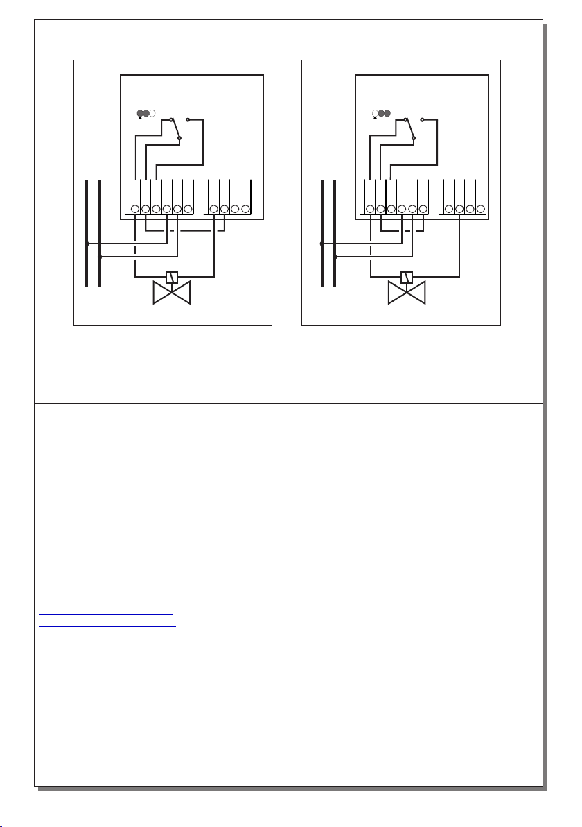
Installation of an electrovalve
The gas supply is automatically turn OFF in the
event of an alarm or fault condition. The electro-
valve can only be reset manually by the user, by
pressing on point “Α” as show in figure 1.
Depending on the type of electro-valve used, the
corresponding connection diagram is shown in
figure 4. Care must be taken to position the link of
JMP1 in the correct position. It is suggested that
this unit is used in cooperation with Οlympia
Electronics Electro-valves type BS-684 (12V
N.O.) Or BS-682 ( 230VAC N.O.). The
connection cable, when you use BS-684, must
be at least 2x2.5mm diameter and no more than
4m length.
There is a screw behind the plastic cover
Figure 1. Remove the plastic cover
Remove the plastic cover using a flat screwdriver
921691000_09_016
Page 2 from 5

Figure 2. Connection diagram of a detector
NC
C
NO
N
+
L
OUT
GND
Z+
Z -
+VS
GND
S
EXTERNAL
BUZZER
Sensor
JMP1
JMP2
JMP3
LN
~230 V
AB
1
1
1
SENSOR
BS-655
BS-542
5K6
+VS
GND
S
BS-692
GND
+12V
K
Θ
BS-660
0,5W
Figure 3a and 3b shows the connection of
multiple detectors in a network connection , for
covering a larger area and using one 12VDC NO
electro-valve or one 12VDC NC electro-valve
Attention!! The position link of JMP1 set the
relay status.
If a link is set on A ( figure 3B ) the relay is
energized (NO) in normal condition and on alarm
or fault condition the relay is not energized.
The oppisite occurs if a link is set on B ( figure
3A).
ATTENTION: If you use electrovalves 230VAC
you can use a fire-siren 230VAC BS-546 and
BS-542 . The connection of BS-546 show in
figure 5. If you use electrovalves 12VDC you can
only use BS-542 .
ATTENTION!! The devices must not be tested
using gas filled lighters because the sensor will
be destroyed.
NC
C
NO
N
+
L
OUT
GND
Z+
Z -
JMP1
AB
1
NC
C
NO
N
+
L
JMP1
AB
1
NC
C
NO
N
+
L
JMP1
AB
1
...
E.V. 12VDC N.C.
1st Vth2nd
Figure 3.Connecting multiple detectors in a network and using one
electro-valve 12VDC N.C.
921691000_09_016
Page 3 from 5

NC
C
NO
N
+
L
OUT
GND
Z+
Z -
JMP1
AB
1
NC
C
NO
N
+
L
JMP1
AB
1
NC
C
NO
N
+
L
JMP1
AB
1
...
E.V. 12VDC N.O.
1st Vth2nd
NC
C
NO
N
+
L
OUT
GND
Z+
Z -
Electro-valve ~230V
Diagram with manual reset and
normally open electro-valve
JMP1
AB
1
Diagram with manual reset and
normally closed electro-valve
LN
~230 V
E.V. ~230V N.C.
BS-546
NC
C
NO
N
+
L
OUT
GND
Z+
Z -
JMP1
AB
1
LN
~230 V
E.V. ~230V N.O.
BS-546
ΑΤΤΕΝΤΙΟΝ! Electrovalve 230VAC N.O. is not recommended for installation with no guarantee
power supply , because in a power failure situation the gas flow will not close.
Figure 3B.Connecting multiple detectors in a network and using one
electro-valve 12VDC N.O.
921691000_09_016
Page 4 from 5

NC
C
NO
N
+
L
OUT
GND
Z+
Z -
Electro-valve 12VDC
Diagram with manual reset and
normally open electro-valve
JMP1
AB
1
NC
C
NO
N
+
L
OUT
GND
Z+
Z -
Diagram with manual reset and
normally closed electro-valve
E.V. 12VDC N.C.
JMP1
AB
1
LN
~230 V
E.V. 12VDC N.O.
LN
~230 V
Figure 4. Diagrams for connecting various types of electro-valves
WARRANTY
Olympia Electronics guarantees the quality, condition and operation of the goods. The period of
warranty is specified in the official catalogue of Olympia Electronics and also in the technical leaflet,
which accompanies each product. This warranty ceases to exist if the buyer does not follow the
technical instructions included in official documents given by Olympia Electronics or if the buyer
modifies the goods provided or has any repairs or re-setting done by a third party, unless Olympia
Electronics has fully agreed to them in writing. Products that have been damaged can be returned to
the premises of our company for repair or replacement, as long as the warranty period is valid.
Olympia Electronics reserves the right to repair or to replace the returned goods and to or not charge
the buyer depending on the reason of defection. Olympia Electronics reserves the right to charge or
not the buyer the transportation cost.
HEAD OFFICE
72nd km. O.N.R. Thessaloniki-Katerini
P.C. 60300 P.O. Box 06 Εginio Pierias Greece
www.olympia-electronics.gr
921691000_09_016
Page 5 from 5
This manual suits for next models
1
Table of contents
Other olympia electronics Gas Detector manuals
Popular Gas Detector manuals by other brands

Eastern Energy
Eastern Energy 7721 Operation manual

Lanberg
Lanberg SR-1005 user manual

Weatherford
Weatherford SLS Baseline 9000 FID manual

RKI Instruments
RKI Instruments GD-70D Series operating manual

Industrial Scientific
Industrial Scientific TANGO TX2 product manual

GASTRON
GASTRON GTD-1000T Series instruction manual