aquilar AquiTron AT-MZA User manual

AT-MZA
Multi Zone Alarm
AquiTron
INSTALLATION
INSTRUCTIONS

MZA
115Vac +15%, -20%; 50/60 Hz
230Vac ±10%; 50/60 Hz
12Vdc ±20%
POWER CONSUMPTION
12 watt maximum
RELAYS
Number: One LEAK relay per zone (max 8),
One common LEAK and one summary FAULT.
Type: SPDT
Rating: 3 A at 250Vac/24 Vdc
TEMPERATURE
Storage: -18°C to 60°C (0°F to 140°F)
Operating: 0°C to 50°C (32°F to 122°F)
ENCLOSURE
NEMA 12; IP54
INSTALLATION ITEMS
(NOT SUPPLIED)
• Wall fasteners for surface mounting (four
screws)
• Rubber or elastomeric washers to seal
at mounting points
• Semi-ush recess ange (optional)
TOOLS REQUIRED
• Drill or hole punch for electrical
conduit entries
• Phillips (cross-head) screwdriver
• Small at-head screwdriver
STORAGE
Keep the module in a dry place prior to
installation to avoid possible damage to
internal components.
ADDITIONAL ITEMS
AT-BU
Battery Unit c/w battery
for 72 hrs operation
AT-BAT
Replacement 12Vdc, 7Ah Battery
AT-MZA-SFMF
Semi Flush Mounting Flange
APPROVALS
The MZA is approved for use in ordinary
areas. The module must be located in an
Ordinary Area, but may monitor intrinsically
safe TraceTek sensing cables located in
Hazardous Locations:
• TraceTek sensing cable in Class I, Division 2,
Groups A, B, C, D =Hazardous Locations.
• If protected by agency-approved zener
barrier TraceTek sensing cable in Class I,
Division 1, Groups A, B, C, D Hazardous
Locations (Zone 0 or Zone 1 in Europe).
Contact your TraceTek distributor/agent
to select proper zener barrier.
MAXIMUM CIRCUIT LENGTH
100m (328ft) TraceTek sensing cable or 10
water or optical oil probes per zone. Leader
and jumper cable lengths are not included
in this limitation.
Please read these
instructions carefully
and keep them in a
safe place (preferably
close to the module)
for future reference.
These instructions
must be followed
carefully to ensure
proper operation.
AT-MZA
Multi Zone Alarm
A. GENERAL INFORMATION
The MZA multi zone alarm has been designed specically for use with TraceTek sensing cables
(TT1000, TT1100, TT3000, TT5000, TT5001 and TT7000). The MZA can monitor per zone up to
100 m (328 ft) of sensing cable, or 10 water detection probes. Optical probes, oat switches
and level indicators can also be incorporated into the system.The MZA is designed for use in
ordinary areas with temperatures of 0°C to 50°C (32°F to 122°F).
B. PRODUCT INFORMATION
LEAK DETECTION SOLUTIONS
Weights & Measures House, 20 Barttelot Road,
Horsham, West Sussex RH12 1DQ
+44 (0) 1403 216100
www.aquilar.co.uk
1

AT-MZA
Multi Zone Alarm
LEAK DETECTION SOLUTIONS
Weights & Measures House, 20 Barttelot Road,
Horsham, West Sussex RH12 1DQ
+44 (0) 1403 216100
www.aquilar.co.uk
1. LEDs with icons
2. Mute Button
3. Reset Button
4. Zone LEDs
5. Battery Connection
6. Spare Fuse
7. Fuse (1600mA, 250 V)
8. Fuse (1600mA, 250 V)
9. Zone exp card connection
10. (Not Used)
11. Power cable terminal block
12. Motherboard
13. Summary leak & fault relay plug & socket
14. Z1/2 Leak relay cable plug and socket
15. Z1/2 Sensing cable plug and socket
16. Z3/4 Leak relay cable plug and socket
17. Z3/4 Se nsing cable plug and socket
18. Z5/6 Leak relay cable plug and socket
19. Z5/6 Sensing cable plug and socket
20. Z7/8 Leak relay cable plug and socket
21. Z7/8 Sensing cable plug and socket
22. Ground/earth stud
23. Ribbon cable
24. Ground/earth stud
25. Buzzer mute link
26. User Interface board
1
2
3
4
5
26
PL PL PL PL
67 89 11 12
25 24 2223 21 20 19 18 17 16 15 14 13
Note: To avoid damage to the MZA and the MZA-EXP electronics, store them in their
cardboard boxes until construction is complete.
2
67 89

AT-MZA
Multi Zone Alarm
LEAK DETECTION SOLUTIONS
Weights & Measures House, 20 Barttelot Road,
Horsham, West Sussex RH12 1DQ
+44 (0) 1403 216100
www.aquilar.co.uk
3
Choose a location indoors where the module will be protected from the elements and
temperature extremes
WARNING: Ignition hazard. Do not mount the MZA unit in a hazardous location. Sensing cable
connected to the MZA may (subject to approvals restrictions) be located in hazardous locations, but
the module itself must
C. SELECT A MOUNTING POSITION
PL PL PL PLPL PL PL PL
Remove all six screws attaching motherboard
Figure 1
PREPARE THE MODULE FOR
MOUNTING
Important: The MZA is an electronic unit.
During installation, take the following
precautions to avoid damage to its electronic
components:
• Handle with care, avoid mechanical
damage.
• Keep the electronics dry.
• If handling circuit boards, hold them by
their edges to avoid physical contact with
electronic components.
• Avoid exposure to static electricity.
• Avoid contamination with metal lings,
liquids, or other foreign matter.
• Remove the module from its packaging.
• Open the enclosure door using a at-blade
screwdriver or coin.
• Anti static precautions should be taken
before touching the boards inside.
• Carefully disconnect the ribbon cable from
the motherboard.
• Unscrew the four Phillips (cross-head)
screws holding the motherboard to
the enclosure (see Fig 1). Remove the
motherboard, and put it out of harm’s way.
• Taking care to protect the User Interface
board on the enclosure door, drill/punch
entries as required (see Fig 2).
PL PL PL PL
Figure 2
Additional area
avalable for
cable entries
(no knockouts)
MOUNT THE MODULE
The module mounts with four screws with
mounting centers as noted in Fig 3. To seal
around the mounting screw (necessary to
maintain the IP54 rating), use a rubber or
elastomeric washer.
• Note: The AquiTronTM/ TraceTek sensing
circuit is power limited, so the TraceTek
leader or jumper cable and the power
supply cable must not run in the same
conduit.
• Fit conduit bushings/adapters.
• Remove all traces of metal lings and dust
from inside the module enclosure.
Figure 2

AT-MZA
Multi Zone Alarm
LEAK DETECTION SOLUTIONS
Weights & Measures House, 20 Barttelot Road,
Horsham, West Sussex RH12 1DQ
+44 (0) 1403 216100
www.aquilar.co.uk
REASSEMBLE THE MODULE
Note: Before replacing the motherboard,
ensure that the interior of
the enclosure is clean.
• Replace the motherboard and secure it in
place with the Phillips (cross-head) screws.
• Reconnect the ribbon cable (taking care not
to bend any pins in the connection).
• Close and secure the door of the enclosure.
4
190m m
240m m
210m m
165m m
Figure 3
Cable entry knockouts are provided as
follows:
Back plate 4 x 20mm and 3 x 3/4”
Base of endourse 6 x 20mm and 5 x 3/4”
D. PREPARE SENSING CABLE / SENSING PROBE / DEVICE
Ensure that the sensing cable (sensing device) has been installed in accordance with the
instructions provided.
MAKE CONNECTIONS
• Conrm that the power to the MZA unit has
been turned o.
• Open the enclosure door.
• Feed the end of the TraceTek modular
leader cable (or bulk jumper cable) through
the knockout/adapter/bushing if tted.
• Connect the four colour-coded wires to the
Sensor Interface plug, X3, X7, X10 and X12
(see Fig 4).
SENSOR
RED
GR N
YEL
BLK
x3
x7
x10
x12
• Select a spare connector between zones 1
to 8.
• Zones 1-2 do not require the insertion of a
zone expansion card, MZA-EXP.
• Three cards can be added to the base unit,
giving a total of 8 individual zones. Provided
the relevant zone expansion card has been
• the relevant zone expansion card has been
inserted, you can select any sequence for
connecting the sensing cable or sensing
devise.
Important: Observe the colour coding.
If wires are not connected to the correct
terminals, the leak detection system cannot
operate properly.
Insert the sensing cable (SI) plug into the SI
socket (item 15, 17, 19, 21 on the product
illustration on the rst page).
ISOLATE SPARE SENSING ZONES
Each spare sensing zone circuit or the second
zone in any of the two zone blocks, where
an expansion card is tted, that is not to
be used must be terminated with loops of
cable between red-green and yellow-black.
(See gure 5). This will prevent the system
identifying this zone as having a cable break.
However, should there be a requirement for
all three-expansion cards to be installed, but
not used, then these must be terminated in a
similar fashion.
Figure 3
Figure 4

SENSOR
RED
GRN
YEL
BLK
x3
x7
x10
x12
Figure 7
AT-MZA
Multi Zone Alarm
LEAK DETECTION SOLUTIONS
Weights & Measures House, 20 Barttelot Road,
Horsham, West Sussex RH12 1DQ
+44 (0) 1403 216100
www.aquilar.co.uk
5
CONNECTING THE POWER WIRING
• Open door of MZA enclosure.
• Pass the power cable through the knock-
out/adapter/bushing if tted.
• Note: Proper grounding/earthing is
important to avoid the possibility of
electromagnetic interference.
• Connect the power supply wires to the
special three-pin terminal block marked LNE
(Live, Neutral, Earth), observing the polarity.
E. CONNECTING THE POWER CABLE AND RELAYS
x15
Figure 4
LN
• The electrical supply should be fused
at no more than 3 amps via an un-
switched fused spur adjacent to the
unit.
• Note: Do not exceed maximum
voltage.
• The unit is equipped with a 12Vdc battery
back-up power circuit. If this option is
required connect the + and - (positive and
negative) battery leads (leads not supplied)
(g 7).
BATTERY BACKUP
Figure 5
• A separate battery unit is available
AT-BU which will house a 12Vdc 7Ah
battery - AT-BAT.
• Batteries should be tested, maintained
and replaced in accordance with the
battery manufacturers instructions
and recommendations.
COCONNECT THE LEAK AND FAULT
(CABLE BREAK) RELAYS
The MZA has:
One LEAK relay per zone
One common LEAK relay
One summary FAULT relay
RELAY IDENTIFICATION
LEAK relays:
Zones1&2,X13-Z1bottom,Z2top
Zones3&4,X11-Z3bottom,Z4top
Zones5&6,X8-Z5bottom,Z6top
Zone7&8,X5 -Z7bottom,Z8top
Note: See gure 8 (at the back of this
document) for a complete gure layout.
Figure 5
Figure 6
Figure 7
AT-MZA
Multi Zone Alarm
LEAK DETECTION SOLUTIONS
Weights & Measures House, 20 Barttelot Road,
Horsham, West Sussex RH12 1DQ
+44 (0) 1403 216100
www.aquilar.co.uk
COMMON LEAK RELAY
X14 Bottom connection
FAULT RELAY:
Common to all zones X14 Top connection
All relays are SPDT and independent of
the next.The MZA’s FAULT relay will also
indicate power failure as the relay contacts
will de-energize to signal an alarm condition.
Therefore, loss of power as well as a cable
break would trip the relay and any equipment
connected.
x14
x13
x11
x8
x5
N/O N/CC
6
Note: The relay plugs can accept wires 12 to
24 AWG. Cable should have a temperature
rating of 65°C.
Note: Maximum load for relays is 3 amps,
250Vac/24Vdc.
F. CONNECTING THE ZONE EXPANSION CARDS
Important: The MZA-EXP is an electronic unit. During installation, take the following
precautions to avoid damage to its electronic components:
• The MZA panel should not be powered
when installing the MZA-EXP card.
• Anti static precautions should be taken
before touching the boards inside.
• Handle with care, avoid mechanical
damage.
• Keep the electronics dry.
• If handling circuit boards, hold them by
their edges to avoid physical contact with
electronic components.
• Avoid exposure to static electricity.
• Avoid contamination with metal lings,
liquids, or other foreign matter.
• A maximum of three MZA-EXP cards can be
added to a MZA panel.
• Each MZA-EXP provides two additional
zones of sensing.
• Remove the card from it’s static free
packaging.
• Insert the rst card on vertical connector
marked zones 3-4 and the following cards
on zones 5-6 and zones 7-8. The card will
only t in one direction.
• Push the card securely to the base
connector.
• Once the card has been securely installed
the MZA panel can be powered.
INSTALL ZENER BARRIER, IF
APPLICABLE
When sensing cable will be located in Class
1, Division 1 locations, approval agencies
require that the sensing cable be protected
with a zener barrier between the sensing
cable and the MZA module. A zener barrier
may also be used to provide lightning
protection for the module when the
sensing cable may be exposed to electrical
discharges. Contact your distributor/agent to
select the proper zener barrier. One will be
required for each sensing zone.
When installing a zener barrier, wire
it in accordance with the instructions
provided with the kit.

AT-MZA
Multi Zone Alarm
LEAK DETECTION SOLUTIONS
Weights & Measures House, 20 Barttelot Road,
Horsham, West Sussex RH12 1DQ
+44 (0) 1403 216100
www.aquilar.co.uk
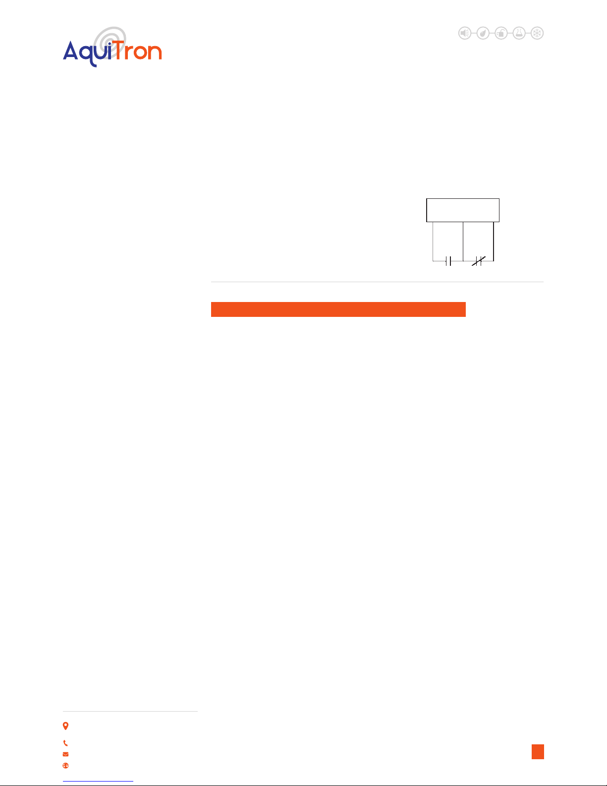
VOLT FREE RELAY OPERATION
All leak detection alarm panels supplied by Aquilar are provided with, at least one, volt free
relay.These are also known as volt free contacts or dry contacts. They are used to operate
auxiliary equipment such as – valves, sounders, pumps, beacons etc., sending closed or open
contact signals to Building Management Systems (BMS) or other logic level controls.
As the name suggests, there is no voltage present at the terminals. So, to operate a valve,
for example, you need to have a dedicated power supply which is then fed through the relay
(typically the live feed) to switch it on or o accordingly.Typical wiring is as follows:
Please ensure that the load does not exceed the ratings of the volt free relay. This is stated in
the relevant product’s data sheet / installation instructions.
Wiring of volt free relays should be undertaken by a suitably qualied technician and in
accordance with the regulations and standards in their industry/country. These notes are only
intended as a guide and Aquilar Ltd bears no responsibility for the installation or operation of
the unit.
7
//
/
/
/
/
/
/
/
/
/
/
/
/
/
/
/
/
/
/
/
/
/
/
/
/
/
/
/
//
//
//
//
//
//
/
/
/
/
/
/
/
/
/
/
/
/
/
/
/
/
//
/
//
/////
//
/
/
/
/
/
/
/
/
/
/
/
/
/
/
/
/
/
//
/////
//
//
/
/
/
/
/
Class I, Division 1
(Zone 0 or Zone 1 in Europe)
Hazardous Location
Ordinary Area
Zener
barrier
Leader or jumper cable
Jumper cable
Sensing cable
MZA

AT-MZA
Multi Zone Alarm
LEAK DETECTION SOLUTIONS
Weights & Measures House, 20 Barttelot Road,
Horsham, West Sussex RH12 1DQ
+44 (0) 1403 216100
www.aquilar.co.uk
G. TEST PROCEDURE
1. After connections are complete supply
power to the unit. If the sensing circuit
is complete and free of leaks or other
problems, the green Monitoring LED only
will illuminate.
2. Leak Simulation: For systems using TT1000,
TT3000 sensor cable or a detection probe,
use a TraceTek Mapping Tool or a small
container of water to simulate a leak. After
the time delay has expired (maximum 15
seconds) look for the following indications:
Red LEAK LED on
Green POWER LED on
LEAK RELAY in ALARM condition
(Note: This may cause equipment shut
down if devices are connected to the LEAK
relay contacts)
Remove simulated leak
Red LEAK LED goes out
For TT5000 and TT5001 systems, simulate a
leak condition by tightly bending and holding
the sensor cable.
3. Cable Break Simulation: For any sensor
system, disconnect any one wire at the
sensor cable terminal block or disconnect
any connector in the system. Look for the
following indications:
Yellow CABLE BREAK LED on
FAULT RELAY in ALARM condition
Restoring the connection should cause the
MZA to return to the normal indications for
that zone.
1. Complete a system inspection in the
presence of the owner.
2. Ensure a plan showing the location of the
sensor is available.
3. Check that the following information
is clearly visible adjacent to the alarm
module:
• In case of alarm instruction.
• Location of the system map in case it
is not installed adjacent to the alarm
module.
• Name and contact number of the person
responsible for operating the system.
• Supplier’s contact name and address.
4. Hand over these Installation, Operating
and Maintenance Instructions.
5. Make the owner aware that it is strongly
recommended to perform a systems
check at regular intervals, at least every six
months.
H. FINAL CHECK LIST
8
COMMISSIONING
Your system should be commissioned
by an authorised AquiTron™ or TraceTek
representative. The system map is a crucial
part of the system and should be located
adjacent to the unit and within the O&M
documents.
Important: Store hardware and
documentation supplied with the MZA in a
secure place for later use (commissioning,
connecting interfaces, operating).
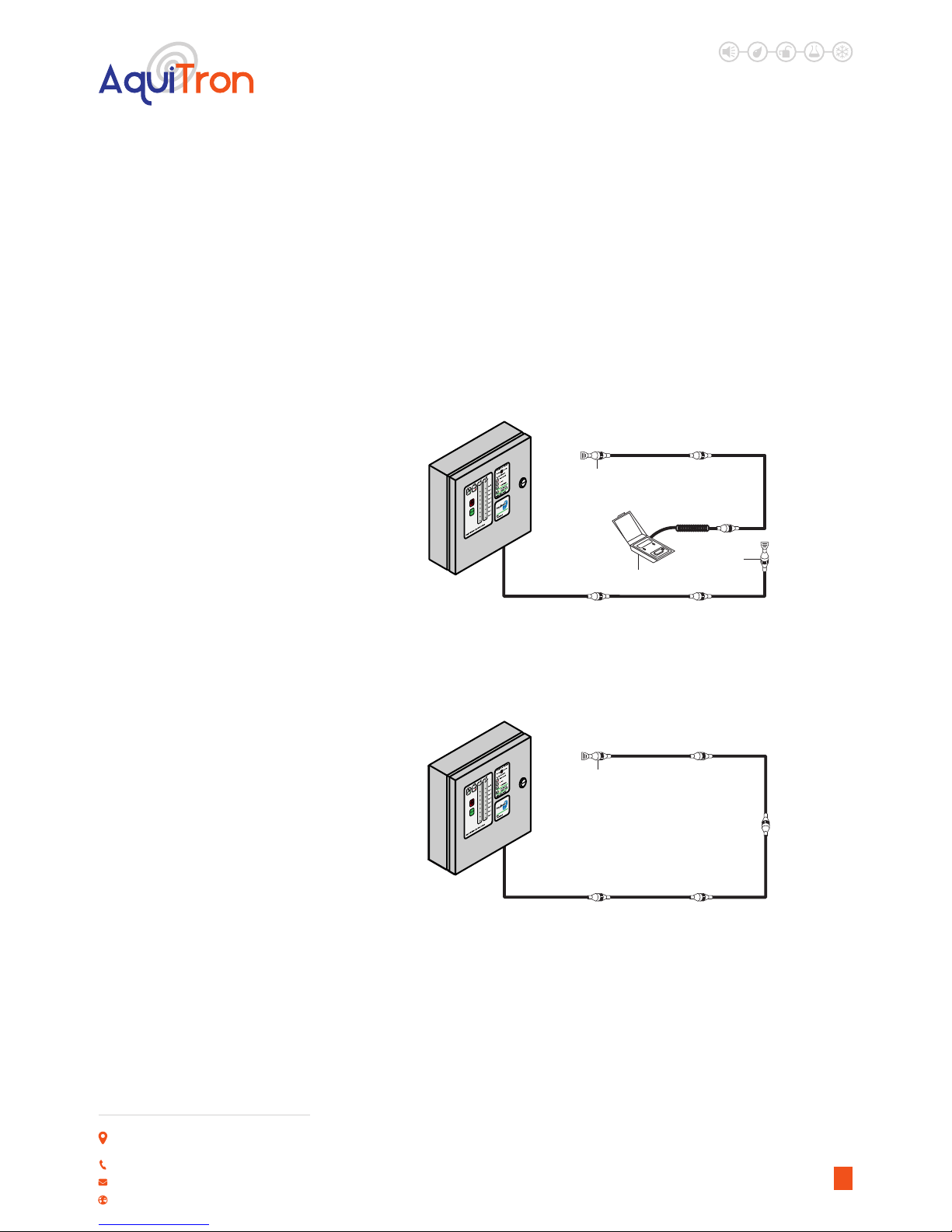
I. INVESTIGATING LEAKS AND FAULTS
If the location of a leak is not apparent, it is often useful to subdivide the leak detection
circuit, as illustrated below. To accomplish this, it is recommend have a TraceTek Portable
Test Box (PTB) and an extra Modular End Termination is used. Contact your local TraceTek
representative to obtain these products. Note that the PTB comes with instructions on how to
use it.
To segment the system (one individual zone) and isolate problems, nd a TraceTek sensing
cable or jumper cable connection at a convenient point somewhere at the center of the
AT-MZA
Multi Zone Alarm
LEAK DETECTION SOLUTIONS
Weights & Measures House, 20 Barttelot Road,
Horsham, West Sussex RH12 1DQ
+44 (0) 1403 216100
www.aquilar.co.uk
9
TraceTek or AquiTron™
Leak detection alarm panel
End termination
TraceTek or AquiTron™
Leak detection alarm panel
End termination
End
termination
PTB
detection circuit. You can then use a PTB to check one portion of the system (to verify circuit
integrity, to detect the presence of liquid, and even to determine its location, as the PTB will give
you an indication in feet or metres to the point of the leak). If you install an end termination on
the other length of cable (going back to the MZA panel), you can use the MZA to check the “front
half” of the sensing circuit.
You can further subdivide the circuit, and even test individual lengths of cables, as shown in the
third diagram below. Even the most perplexing problems can usually be isolated and resolved
using this methodical approach.

AT-MZA
Multi Zone Alarm
LEAK DETECTION SOLUTIONS
Weights & Measures House, 20 Barttelot Road,
Horsham, West Sussex RH12 1DQ
+44 (0) 1403 216100
www.aquilar.co.uk
J. CLEANING THE MODULE
To clean the outside surface, use a damp
cloth or sponge. Do not use solvents or
abrasive cleaners, and do not open the
enclosure while it is wet (it is an electrical
device).
L. FUSE REPLACEMENT
The fuse on the power supply board (item 7
on the internal layout drawing) is a 1600-mA,
250-V. Use no other type of fuse or the MZA
could be damaged or fail to perform properly.
A spare fuse is provided and positioned on
the mother board item 4.
K. STORAGE AND HANDLING
OF SENSING CABLE
M. NOTE ON CABLE
CLEANING
Despite their rugged construction, TraceTek
sensing cables must be handled in a
manner appropriate for a sensing device
or they may be damaged and require
replacement. Therefore, you should follow
some basic rules for storing and handling all
TraceTek sensing cables:
• Store spare cable in its original container
in a clean, dry place until ready for
installation.
• Schedule cable and probe/sensor
installation after all mechanical, plumbing,
and electrical work has been completed.
• Clean the area where the cable is to be
installed, and remove any obvious debris
or other sources of contamination.
• Do not solder or weld near the cable
without providing protection from heat,
solder ux, or weld splatter.
• Do not drop tools or oor tiles on the
cable; sharp and heavy objects may
damage the cable.
• Avoid walking or stepping on the cable.
Provide shielding (for example, a half
shell of plastic pipe) where additional
protection is necessary.
• Do not use tape to secure sensing cable
(some tapes and adhesives absorb
moisture) or use solvents that could
eventually cause an alarm.
• Do not drag sensing cable through
contaminants (such as pipe dope, PVC
cement, solvents, oil, or dirt).
TraceTek TT1000 and TT3000 use a solid
core polymer construction and can usually
be easily cleaned with tap water. In extreme
cases or when large amounts of cable are
contaminated, either cable can be washed
in an ordinary dishwasher. Try a water only
(no detergent) cycle rst and avoid the
heated dry cycle. When placing the cable in
the dishwasher be sure to tightly connect
the male connector on one end to the
female connector on the other. Keep water
out of the connectors.
TT5000 and TT5001 cannot be cleaned
without special equipment. These cables
normally require replacement after
exposure to fuel or solvent.
N. PERIODIC MAINTENANCE
AND TESTING
Recommended Interval: Perform a
functional check per the following procedure
at 6-month intervals. Repair or replace all
damaged wiring and senor cables. There are
no eld repair procedures for the MZA panel.
If the module fails to perform the functional
tests it must be replaced
10

AT-MZA
Multi Zone Alarm
LEAK DETECTION SOLUTIONS
Weights & Measures House, 20 Barttelot Road,
Horsham, West Sussex RH12 1DQ
+44 (0) 1403 216100
www.aquilar.co.uk
O. TROUBLE SHOOTING
Problem:
Leak Alarm, but no leak is found.
Possible Cause:
Cable is dirty (TT1000, TT3000).
Action:
Clean cable using water (no solvents, acetone,
white spirit or turps). Dry the cable and
check MZA front panel. Heavily contaminated
cable may require replacement. But if dirt is
accumulating, cleaning and/or replacement
will eventually be required.
Problem:
Leak Alarm, but no leak is found.
Possible Cause:
Cable is exposed to occasional water spraying
(TT1000, TT3000)
Action:
It is best to keep the sensor cable at least
1 meter (3 feet) from the outow of any air
conditioner units.
Problem:
Leak Alarm, but no leak is found.
Possible Cause:
Cable is in contact with sharp metal edges
(TT1000, TT3000)
Action:
Check the sensor cable for possible points of
contact with sharp edges such as the edges of
drip trays or the pipe threads on adjustable
oor supports, trunking and ducting.
Reposition the cable as necessary or insert a
small piece of insulating material to prevent
the cable from making contact with the metal
edge.
Problem:
Leak Alarm, but no leak is found.
Possible Cause:
Cable is pinched (all cables).
Action:
Check the sensor cable for possible pinch
points. TT5000 and TT5001 can be tripped if
tightly bent or compressed by a heavy object.
TT1000 and TT3000 can be tripped by heavy
pressure from a metallic object. Check the
entire cable installation for pinch points and
correct the condition.
Problem:
CABLE BREAK indication but cable appears to
be intact. Possible
Cause:
Loose connections at terminal block.
Action:
Check all terminal block screws for tightness.
To test the module by itself, use two small
pieces of wire to form temporary jumpers
from red to green and yellow to black at the
sensor cable terminal block. This simulates
a very short piece of sensor cable and the
yellow CABLE BREAK LED should go o. If the
MZA cannot pass the jumper wire test it may
require replacement.
Problem:
BMS/PLC or other host system detects a
fault when the MZA is operating in NORMAL
mode.
Possible Cause:
Mains power has cycled. Logic controller has
powered relays incorrectly.
Action:
Press RESET button. This will clear any logic
power up anomalies, and the panel will now
function correctly.
11

AT-MZA
Multi Zone Alarm
LEAK DETECTION SOLUTIONS
Weights & Measures House, 20 Barttelot Road,
Horsham, West Sussex RH12 1DQ
+44 (0) 1403 216100
www.aquilar.co.uk
NORMAL MODE INDICATIONS:
LEAK LED (Red) OFF
CABLE BREAK LED (Yellow) ON
POWER LED ON (Green) ON
ALARM/TROUBLE RELAY NORMAL (de-enrgised)
LEAK MODE INDICATIONS:
LEAK LED (Red) ON
CABLE BREAK LED (Yellow) OFF
POWER LED ON (Green) ON
ALARM/TROUBLE RELAY ALARM(enrgised)
USER ACTION
1. Locate the spill area, investigate the cause of the spill and take necessary repair actions.
2. Clean up in the spill area and clean and dry the cable / probe, if necessary. LEAK LED will turn
o when cable / probe is dried.
CABLE BREAK INDICATIONS:
LEAK LED (Red) OFF
CABLE BREAK LED (Yellow) ON
POWER LED ON (Green) ON
ALARM/TROUBLE RELAY ALARM(enrgised)
USER ACTION
1. Investigate the sensor cable and leader cable for physical damage. Check connectors for
damage. Make repairs or replace components as necessary.
2. CABLE BREAK LED automatically turns o when normal sensor cable continuity is restored.
The Alarm Relay automatically returns to the NORMAL position when cable continuity is
restored.
12
AT-MZA
Multi Zone Alarm
LEAK DETECTION SOLUTIONS
Weights & Measures House, 20 Barttelot Road,
Horsham, West Sussex RH12 1DQ
+44 (0) 1403 216100
www.aquilar.co.uk
13
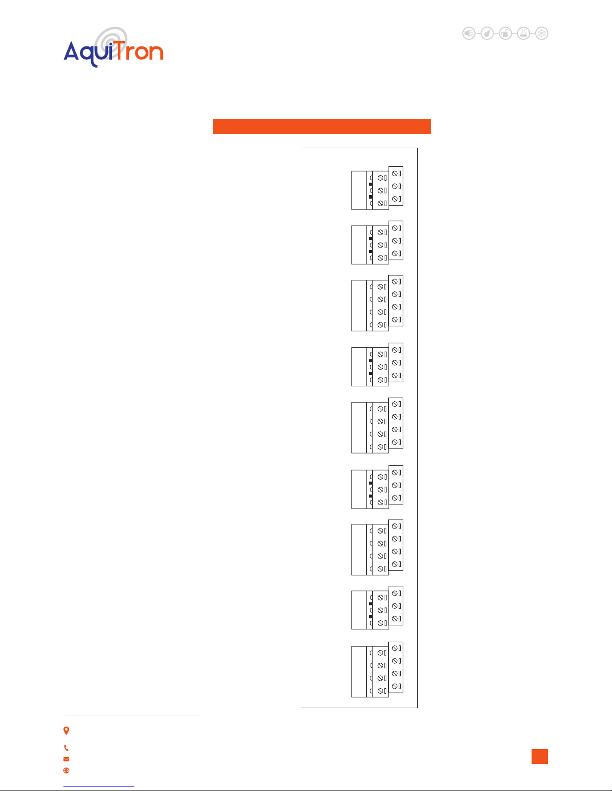
FIG 8. TERMINAL CONNECTION LAYOUT
SENSO R
RED
GR N
YEL
BL K
Z8
x3
Z7
N/O
CO M
N/C
LEAK
REL AY
x5
SENSO R
RED
GR N
YEL
BL K
Z6
x7
Z5
SENSO R
RED
GR N
YEL
BL K
Z4
x10
Z3
SENSOR
RED
GR N
YEL
BL K
Z2
x12
Z1
31x11x8x
N/O
CO M
N/C
x14
TO P
FA UL T COMMO N
BOTTO M
LEAK COMMO N
N/O
CO M
N/C
LEAK
REL AY
N/O
CO M
N/C
LEAK
RELA Y
N/O
CO M
N/C
LEA K
RELA Y

Important: All information, including illustrations, is believed to be reliable. Users, however,
should independently evaluate the suitability of each product for their application. Aquilar
Limited makes no warranty as to the accuracy or completeness of the information, and
disclaims any liability regarding its use. The only obligations of Aquilar Limited are those in
the Aquilar Standard Terms and Conditions of Sale for this product, and in no case will Aquilar
Limited be liable for any incidental, indirect, or consequential damages arising from the sale,
resale, use or misuse of the product. Specications are subject to change without notice. In
addition, Aquilar Limited reserves the right to make changes – without notication to Buyer
– to processing or materials that do not aect compliance with any applicable specication.
AquiTron is a trademark of AquiTron Limited
Aquilar is a trademark of Aquilar Limited
TraceTek is a trademark of Pentair
AT-MZA
Multi Zone Alarm
LEAK DETECTION SOLUTIONS
Weights & Measures House, 20 Barttelot Road,
Horsham, West Sussex RH12 1DQ
+44 (0) 1403 216100
www.aquilar.co.uk
14
V4 5.2018
Table of contents
Other aquilar Security System manuals


Popular Security System manuals by other brands


Bulldog Security
Bulldog Security 742 Installation and owner's guide

RSI
RSI XL600 COMPLETE SETUP AND PROGRAMMING MANUAL

Vip-Vision
Vip-Vision SLR-A75-4G installation guide

NexxTech
NexxTech 4900424 owner's manual

National Security Systems
National Security Systems Security System owner's manual

Wheelock
Wheelock NS-1215W installation instructions


