AR I-CHARGE User manual

1
Pocket Charge

2
Thank you for your purchase of the Advance Radio I-Charger
In this quick start guide we will show you how to connect, set up, and general
usage of your new I-Charger . Please take the me to understand this guide
before usage.
IMPORTANT
The I-Charger is a highly advanced piece of technology capable of charging up
to 3 baeries at any one me. Although we have included many safety devices
into the I-Charger to ensure a safe charging environment. Monitor your baer-
ies while charging. Never leave baeries un-aended while charging.
The I-Charge is capable of up to 2amps per stack, this can generate a large
amount of heat. We always recommend using the I-Charger in a well venlat-
ed area. Always remove the canopy while charging inside a model. Never
charge in a sealed area.
Included Items
1 x I-Charger, Pocket Charge or Turbine Charge
1 x Instrucon Manual
Oponal Items
Temperature probe
Addional Charge board
Required items
12 DC ltered power supply, or 12V DC car baery

3
I-Charge Features and Specicaons:
32 bit Processor for crisp display and highest resoluon in the industry.
Bright full colour OLED for easy day me usage
reading of pack voltage, instantaneous charge current and mAh charge
amount into the pack
Automac charging, simply connect 12 volts.
Available in 3 Stack with addional stack addable.
Charges at up to 2A per pack. Charge current is automacally selected by
the advance charge algorithm.
Auto on-board over heat funcon limits charge current if temperature be-
comes too high.
Oponal external temperature sensors for charging LiPo pack. Au-
tomacally stops charge funcon if pack temperature climbs above
40C/100F. Charge funcon resumes when temperature decreases to safe
working level.
Maximum input voltage 15.5 volts.
Minimum input voltage 10.5 volts.
Weight is only 78 grams 2.9oz (3 Stack Version).
Dimensions (3 Stack Version) 62mm x 47mm x 35mm (2.4 x 1.86 x 1.43
inches).

4
Works Best with Booma RC
Self balancing Baeries

5
I-Charger Funcons
I-Charge is designed to charge 2 cell Life (6.6v), Lion(8.2v), LiPo (8.4v) and 3S LiFe (10.8v Tur-
bine version only) baeries. You simply set the baery type on each stack slider switch. Con-
nect your baery and when ready to charge simply connect a 12 volts DC power supply. It is
really that simple.
Quick Set up
Set Baery type for each charge board port with the slider
Plug in the baeries
Plug the ultra connector into the 12v power supply
Check the screen to see that all ports are charging
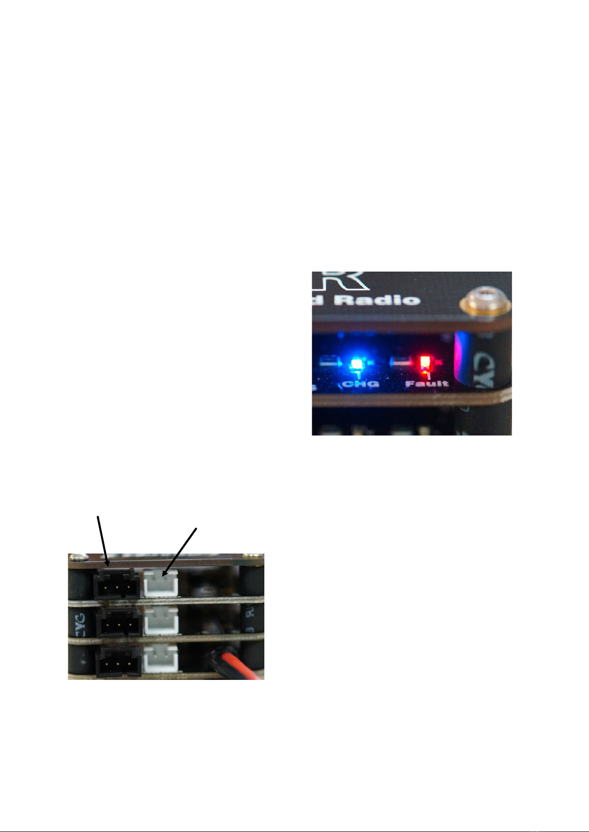
Check to see that the LED blue lights are on.
Please read on for more detailed instrucons
Note—The I-Charge is designed to be used with baeries that have a built in self balancing
circuit.
I Charger Safety Features
Baery over temperature safety.
I Charger has provision for Lithium baery temperature monitoring. This feature monitors
baery pack temperature using the oponal temperature sensor. You simply aach an op-
onal temperature probe to the baery with tape and if the baery temperature moves out-
side a safe charging range of 0°C to 40°C or 104° Fahrenheit , the I Charger suspends charging
and signals a fault condion (Red LED). Once temperature returns to the safe range then
charging will connue.
Bad Baery Detecon
I Charger also has bad baery detecon, which triggers a charge fault (Red LED) if a baery
stays in precondion mode for more than one eighth (23 minutes) of the total charge cycle
me.
Automac Charger Over Temperature Safety
During the charge process the I Charger monitors each charger board individually. If the tem-
perature of an individual charge board reaches a high temperature condion then the charge
current on that charge board is reduced to maintain a safe operang temperature range. This
applies to each individual charge board.

6
Charger Overview
I-Charger Mounng
The Advanced Radio I-Charger has been designed as a lightweight charger that can be either
portable or permanent (mounted inside a model). The I-Charger will generate heat when
charging batteries. YOU MUST provide adequate space when mounng the I-Charger in your
model. It is advised that you mount the I-Charger vercally so that thermal cooling is maxim-
ized. Failure to provide an adequate cooling environment will result in lower charge currents
and a longer charge me.
Charger LEDs
Blue CHG LED— Shows charging
has commenced. Will glow when
baeries are charging, once charging
has nished LED will turn o.
RED Fault LED—Shows that there is
an issue with the charge process.
Plugs and Power
Black connector—Charger port, This is the
charge output, simply plug in a JR charge con-
nector here and charging will commence on that
charger stack.
Note—Always check the chemistry on each
stack before plugging a baery in to charge.
White Plug—Temperature probe port, insert op-
onal temperature probe here to monitor
baery temp while charging.
Ultra, Deans, T connector - Power input for the
charger.
B1 Stack
B2 Stack
B3 Stack
Charger port Temperature probe
port

7
I-Charger Turbine stack
Chemistry selector switch
Selector Switch—Move this to
match the chemistry of the baery
you wish to charge.
Note—Each stack has its own selec-
tor switch located under the chemis-
try text. Each stack can be set inde-
pendently.
Chemistry selector— Shows the
available chemistries the stack can
charge.
Note—I-Charge turbine includes a 3s
capable board (Blue stack). This stack
combines LiPo and Lion chemistries
into a single charge output and adds
LiFe (3S) as an opon.
I-Charger Stack
I-Charge Screen (I-Charge and I-
Charge Turbine Versions only)
B1, B2, B3—Shows the informaon of each
baery from top to boom.
Charge arrow—Shows charge process has
commenced.
Baery Voltage—shows baery voltage.
Charge current—shows current charging into
packs.
Milliamp counter—shows total milliamps
charged for each baery.
Note—Screen will turn on as soon as power is
suppled to the I-Charger

8
Step 1
First note that the charge ports (Boards) are numbered from the top down, so a 3 Stack
charger will have the top charge port as number one and the one below that number two
and the boom one number three.
The LCD screen plate is above the number one charge port. The LCD displays each baery’s
informaon also from top down and is indicated as B1, B2, B3.
Step 2
Under each Charge board you will see a small slider switch. This slider switch determines
what baery chemistry and charge voltage is applied to each charge port. You will see that
the charger accommodates LiPo, Lion, LiFe (standard charge board) as well as LiFe 3s
(turbine charge board).
PLEASE NOTE:
BEFORE CONNECTING THE BATTERY OR 12volt POWER please set the slider switch to
match the baery chemistry. Failure to do so could result in the baery pack receiving an
incorrect charge voltage and might damage the baery pack.
I-Charge is designed to use with baeries that have an internal baery balancing charge
circuit.
If you are an advanced user then you know that some baery chemistries do not require
charge balancing however Advanced Radio states that I-Charger should be used only with
self balancing baeries.
I-Charge First Time Setup
B1 Stack
B2 Stack
B3 Stack
I-Charger Turbine stack I-Charger Stack
Chemistry Slider Switch

9
Step 3
On the opposite end of the charger you will noce that there are three sets of black charge plugs
(three pin plug) and three sets of white temperature plugs (two pin plugs).
Plug the baery into the Black (three pin) charge port connector. You can plug your baery into
the bat pins either way as the centre is posive and both outside pins are negave.
This step can be done for each stack.
The TMP port can be used with the oponal temperature sensor. These can be placed on the
baery to warn of excessive temperature.
Step 4
I Charger is supplied with an ultra male connector so you can connect directly to a 12volt
baery or a 12 volt DC power supply to start the charge process.
Please Note: If connecng to a DC power supply it must be able to supply 5A at 12volts DC.
When charging with a 12volt baery please ensure the baery is fully charged as the I-
Charger can draw up to 5A while charging 3 baeries.
Charger port Temperature probe
port

10
Step 5
When the charger rst powers up you will see the AR logo on the LCD screen followed by the
lisng of the baeries 1, 2, 3 etc. Next to the B1 you will see the voltage reading of the baery,
next to that you will see the amps it is charging at. Below this B 1 line is a sequenal colour bar
showing that the is I-Charger working. To the right of this is the amount of MA that the charger
has put into the pack.
Baery Indicator Charge Voltage Charge Current
Charge in process indicator mA Charge Indicator
Step 6
Next to the slider switch on each Charge Port You will see a BLUE LED and a RED LED. The blue
LED is a charge indicator and the red LED is a fault indicator.
These LEDs have the following meaning.
BLUE LED FLASHING = The charger is connected to a 12 volts supply but has no baery connect-
ed.
BLUE LED SOLID = The charger is in the baery charging process.
BLUE LED OFF = The charger has nished the main charge process and is in trickle charge mode.
RED LED = SOLID There is a baery fault. This could be:
1) Baery over temperature (if using the oponal temperature probe). The charge process will
stop unl the baery returns to the safe temperature range.
2) A bad baery that sll has a low voltage aer 23 minutes of start-up charge and cannot be
charged.
3) A 3 hour period has been reached and the baery is sll not completely charged.

11
Step 7
To start the charging process it is a simple process of connecng a 12 volt power sup-
ply. As soon as you connect the 12 volt supply the AR Logo is shown for a brief mo-
ment, the charger boards are reset and (if baeries are connected) the charge process
begins.
How I Charger Works
Aer seng up the desired baery pack chemistry (Life, Lion, LiPo) via a small slider
switch, you simply connect a 12 volt power supply to the I-Charger.
Once power is applied the charger will:
1) Automacally enter a baery precondion mode where it tests the baery voltage.
If the baery voltage is low the charge current is reduced to 15% of the programmed
maximum and applied unl baery voltage reaches 70% of expected fully charged oat
voltage.
2) Once the baery voltage reaches 70% of the expected fully charged oat voltage I-
Charger automacally increases maximum charge current to the full charge value (up
to 2A).
3) I-Charge will then charge the baery pack at full current
(up to 2A) unl expected fully charged oat voltage is reached.
4) At reaching expected fully charged oat voltage, I-Charger reduces high charge cur-
rent proporonally as the baery internal resistance increases.
Upgrading to a 4 Stack Charger
The I-Charge, Pocket charge and I-Charge Turbine can be upgraded to a 4 stack charger
with the addion of another stack. This stack can be either a standard I-Charger Stack
(Black) or a Turbine Stack (Blue) Each charger will only work with up to 4 stacks. Details
for how to do this will be available at www.boomarc.com.

12
I am charging the same type of baery. Why does one I Charger mA meter show a
dierent value to the others?
Baeries have an internal resistance. Think of this as a force attempng to stop current
from owing into the baery. Not all baeries have the same internal resistance. A
baery with a lower internal resistance will take up charge more readily. I Charger uses
individual charge circuitry for each charge port. Each circuit charges one baery. The com-
binaon of baery internal resistance, connector and extension lead resistance may show
as a higher mA charge into one baery when compared to another.
I have noced that the mA and charge current indicaon is sll showing a small charge
aer the main charge is complete.
This is quite normal. The I Charger has a special top up technology that will trickle charge
a baery aer the main charging is complete. What you are seeing is the trickle charge
feature in operaon.
12 Month Replacement Warranty
Advanced Radio will replace this product within 12 months if found to be defecve in
material and/or workmanship when used in the intended purpose. The warranty does
not cover - Shipping charges related to any warranty claim. An over voltage or over
current usage beyond stated specicaon. Damage due to system failure, negligence,
abuse, accident, improper installaon or freezing. Loss of me, inconvenience, loss of
model, or other incidental or consequenal damages.

13
Notes

14
Notes

15
Notes

16
Notes
Table of contents