ARAG Skipper LT Quick start guide

Satellite navigator
Software rel. 2.0X
inStallation, uSe and maintenance
467020

2
•LEGEND SYMBOLS
=Generic danger
=Warning
This manual is an integral part of the equipment to which it refers and must accompany the equipment in case of sale or change of ownership. Keep it for any
future reference; ARAG reserves the right to modify product specications and instructions at any moment and without notice.
LEGEND SYMBOLS

3
contentS
• Legendsymbols...................................................................................................................................................................................... 2
1 Productdescription ................................................................................................................................................................................ 5
2 Intendeduse............................................................................................................................................................................................ 5
3 Precautions ............................................................................................................................................................................................. 5
4 Contentsofthepackage ........................................................................................................................................................................ 5
5 Installation............................................................................................................................................................................................... 6
5.1 Introduction..................................................................................................................................................................................... 6
5.2 System configuration ...................................................................................................................................................................... 6
5.3 General precautions for locating the Skipper LT and cable runs .................................................................................................... 6
5.4 Overall dimensions ......................................................................................................................................................................... 7
5.5 Skipper LT navigator position.......................................................................................................................................................... 7
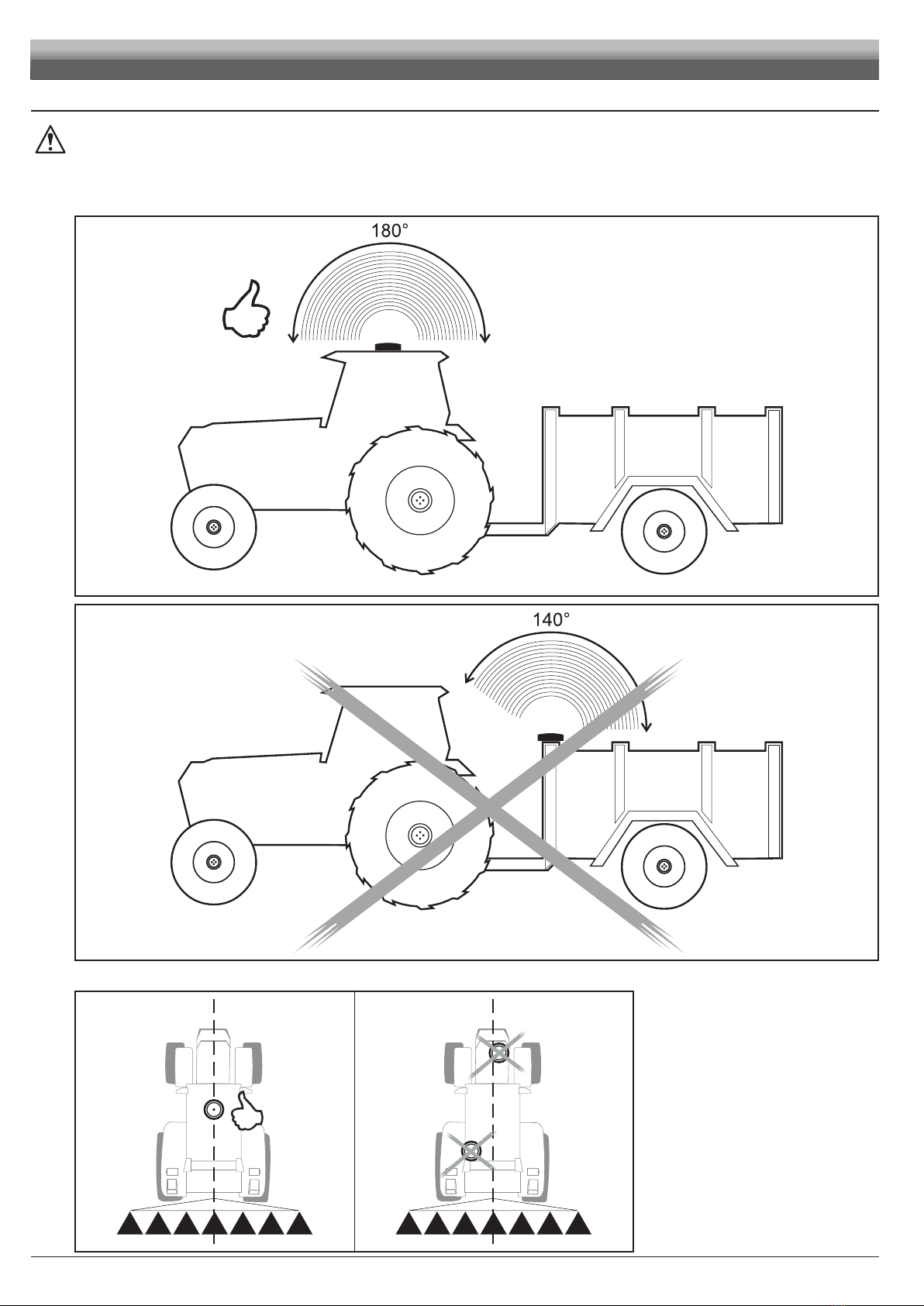
5.6 Locating the antenna ...................................................................................................................................................................... 8
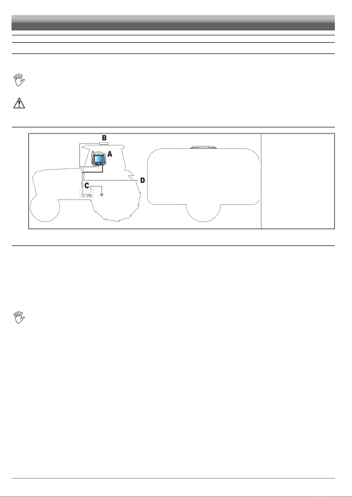
5.7 Electrical connections - general diagram...................................................................................................................................... 10
5.8 Connection to the GPS antenna ................................................................................................................................................... 10
5.9 Treatment status signal..................................................................................................................................................................11
5.10 Connection to the power source ....................................................................................................................................................11
6 Programming......................................................................................................................................................................................... 12
6.1 Switching on ................................................................................................................................................................................. 12
6.2 Switching off.................................................................................................................................................................................. 13
6.3 Using the programming keys ........................................................................................................................................................ 14
6.4 Programming menu ...................................................................................................................................................................... 15
6.5 Machines setup ............................................................................................................................................................................ 16
6.5.1 Boom sections.......................................................................................................................................................................................... 17
6.5.2 GPS antenna ............................................................................................................................................................................................ 18
6.5.3 Alarms....................................................................................................................................................................................................... 19
6.5.4 User Preferences...................................................................................................................................................................................... 20
6.6 Memories management................................................................................................................................................................ 23
6.6.1 Internal memory........................................................................................................................................................................................ 23
6.6.2 Pendrive ................................................................................................................................................................................................... 25
6.6.3 Load/Save settings................................................................................................................................................................................... 26
6.6.4 Preparing the Pendrive for data exchange............................................................................................................................................... 28
6.7 Options ......................................................................................................................................................................................... 29
6.7.1 Language ................................................................................................................................................................................................. 29
6.7.2 Time zone ................................................................................................................................................................................................. 29
6.8 Test ............................................................................................................................................................................................... 30
6.8.1 Display test ............................................................................................................................................................................................... 30
6.8.2 Keyboard test............................................................................................................................................................................................ 30
6.8.3 GPS data .................................................................................................................................................................................................. 30
7 Use ......................................................................................................................................................................................................... 31
7.1 Using keys .................................................................................................................................................................................... 31
7.2 Display .......................................................................................................................................................................................... 32
7.3 Spraying boom.............................................................................................................................................................................. 33
7.4 Spraying a field ............................................................................................................................................................................. 34
8 Workfunctions ...................................................................................................................................................................................... 35
8.1 Functions List: PAGE 1 - SECTION VALVES COMMANDS.......................................................................................................... 36
8.1.1 F1 Open (LEFT) ...................................................................................................................................................................................... 36
8.1.2 F2 Open (RIGHT).................................................................................................................................................................................... 36
8.1.3 F3 Close (LEFT) ...................................................................................................................................................................................... 37
8.1.4 F4 Close (RIGHT).................................................................................................................................................................................... 37
8.1.5 F5 Open All ............................................................................................................................................................................................. 37
8.2 Functions List: PAGE 2 ................................................................................................................................................................. 38
8.2.1 F1 Pause ................................................................................................................................................................................................. 38
8.2.2 F2 Mode.................................................................................................................................................................................................. 39
8.2.3 F3 Return................................................................................................................................................................................................. 40
8.2.4 F4 Align ................................................................................................................................................................................................... 41
8.2.5 F5 Area.................................................................................................................................................................................................... 42
8.3 Functions List: PAGE 3 ................................................................................................................................................................. 43
8.3.1 F1 Mark AB ............................................................................................................................................................................................. 43
8.3.2 F2 Day / Night ......................................................................................................................................................................................... 44
8.4 Functions List: PAGE 4 ................................................................................................................................................................. 45
8.4.1 F1 New job.............................................................................................................................................................................................. 45
8.4.2 F2 2D-3D................................................................................................................................................................................................. 46
8.4.3 F3 Job resume ........................................................................................................................................................................................ 47
8.4.4 F4 Menu .................................................................................................................................................................................................. 48
8.4.5 F5 Erase .................................................................................................................................................................................................. 49
CONT'D
CONTENTS

4
9 Maintenance/diagnostics/repairs .................................................................................................................................................... 50
9.1 Error messages ............................................................................................................................................................................ 50
9.2 Troubleshooting ............................................................................................................................................................................ 50
10 Technicaldata ....................................................................................................................................................................................... 51
10.1 Displayed data and relevant units of measurement ...................................................................................................................... 51
11 End-of-lifedisposal............................................................................................................................................................................... 52
12 Guaranteeterms.................................................................................................................................................................................... 52
CONTENTS

5
INTRODUCTION
1 PRODUCT DESCRIPTION
SKIPPER LT is a satellite navigation system that can be used for agricultural spraying and navigation applications, once connected to the external
GPS antenna.
2 INTENDED USE
Thisdeviceisdesignedtoworkonagriculturalmachineryforcropsprayingapplications.
ThemachineisdesignedandbuiltincompliancewithENISO14982standard(Electromagneticcompatibility-Forestryand
farmingmachines),harmonizedwith2004/108/ECDirective.
SkipperLTisnotaroadnavigatorandshouldonlybeusedonagriculturalland.
3 PRECAUTIONS
•Donotaimwaterjetsattheequipment.
•Donotusesolventsorfueltocleanthecaseoutersurface.
•Donotcleanequipmentwithdirectwaterjets.
•Complywiththespeciedpowervoltage(12Vdc).
•Ifdoingarc-welding,disconnecttheconnectorsfromSkipperLTanddisconnectitspowercables.
•OnlyuseARAGgenuinesparepartsandaccessories.
4 CONTENTS OF THE PACKAGE
The table below shows the components you will nd inside the Skipper LT satellite navigator package:
Fi g . 1
Legend:
1SKIPPER LT satellite navigator
2Mounting bracket kit
3Power supply cable
4Instruction manual and CD-rom
5GPS Antenna
6Antenna base
7Both sides adhesive tape for
antenna base

6
5 INSTALLATION
5.1 Introduction
Installation of the Skipper LT system does not require specialist knowledge.
We recommend however that this be done by a qualied technician in as much as the installation also requires electrical connections to be made.
ARAGISNOTLIABLEFORANYDAMAGECONSEQUENTONINSTALLATIONBYUNQUALIFIEDPERSONS.
IFCASEOFDAMAGETOTHESYSTEMCAUSEDBYINCORRECTINSTALLATIONORCONNECTIONS,THEWARRANTYISAUTO-
MATICALLYVOIDED.
CAUTION!DONOTCONNECTANYANTENNADIFFERINGFROMTHERECOMMENDEDONE(art.no.520110.600).
ARAGWILLBEHELDHARMLESSFROMANYLIABILITYINCASEOFPRODUCTDAMAGES,FAULTSANDRISKSOFANYKIND
CAUSEDBYTHECONNECTIONOFTHEMODULEWITHNON-ORIGINALANTENNASORANTENNASNOTSUPPLIEDBYARAG.
5.2 Systemconguration
Fig. 2
Legend:
ASKIPPER LT satellite navigator
BGPS antenna
CBattery
DTreatment status signal +12 Vdc
(from main control valve)
5.3 GeneralprecautionsforlocatingtheSkipperLTandcableruns
PositioningtheSkipperLTdeviceinthecab:
-DONOTplacethenavigatorinareassubjecttoexcessivevibrationsandshocksorclosetomovingpartswhichmightcause
damages;
-Mounttheremotecontrolunitinavisibleposition,withoutobstructingtheoperator’sview,andwithineasyreachbyhand;
-Takecaretopositionthedeviceawayfrommovingpartstoavoidaccidentaloperationofitskeys.
Insertingtheconnectors:
-FitsuppliedO-ringsintoconnectorsandthenconnectpayingspecialattentiontothenotch.
Pressgentlyandthentightentheringnut.
WARNING:Tightenconnectorringnutsngertight.Donotuseanytools.
-Donotforceinsertionofconnectorsbypressingexcessivelyorbending:contactscoulddamageandcompromisecorrect
operationofthemonitor.
Securingthecables:
-NotethevariousconnectionsrequiredfortheSkipperLTsystemtooperate,thenecessarylengthofthecables,andensure
thatthereissufficientspaceforthecablerunsandconnectors;
-Routethecablesinsuchawaythattwistingandmachinemovementscannotdamageorbreakthem;
-Routethecablesinsuchawaythattheycannotcomeintocontactwithmovingparts;
-If,duetolimitedspace,thecablinghastorunaroundacorner,makesurethatthe
bendisnottoosharpasthismaycausethecabletobreak.
UseONLYtheaccessoriesindicatedinthecatalogue,havingtechnicalfeaturessuitablefortheusetobemadeofthem.
INSTALLATION

7
5.4 Overalldimensions
Fig. 3
Legend:
1USB HOST port (pendrive, etc...)
2GPS Antenna
3Power supply - Treatment
status signal
5.5 SkipperLTnavigatorposition
Beforepositioningthesatellitenavigator,carefullyreadallinformationgivenunderpar.5.3-Generalprecautionsforlocatingthe
SkipperLTandcableruns.
Position Skipper LT centrally into the cabin so that it does not impair driving visibility while allowing data check during treatment.
Fi g . 4
1) Position the mounting rail in the cabin using the suitable
supplied screws, in a position where the navigator is in
view and within hands reach, but away from any moving
organs.
2) Fasten navigator by tting it to the rail and pushing down
until it locks in place.
INSTALLATION

8
5.6 Locatingtheantenna
TheusermustpositiontheGPSantennaasindicatedinthismanualandmakesurethatthemodiedvehicleheightdoesnot
leadtoanimpactwithanyobstacle.
Installing the antenna:
Installation of the antenna on agricultural equipment must observe certain basic requirements:
• it must be installed on the highest point of the machine (including trailer): the skywards reception angle must be as unobstructed as possible.
Fig. 5
Fig. 6
The antenna must be installed on the lengthwise axis of the machine.
Fig. 7 Fig. 8
INSTALLATION

9
Antenna fastening:
The antenna has a magnetic base and should be positioned on a at metal surface (e.g. farm machine roof). In case of plastic roof, use the supplied
metal plate and sticker.
Remove one of the protective lms from the sticker and stick it onto the metal plate.Then remove the other protective lm and position the plate where
the antenna is being tted after cleaning the whole area.
Itisimportantthatthemetalplateandtheantennaarepositionedontoaatsurfacefreefromanyobjectswhichmightreduce
adhesiveadherence.
Fig. 9
Checkforpropermetalplatexingatregularintervalssotoavoiditsaccidentaldetachment.
INSTALLATION

10
5.7 Electricalconnections-generaldiagram
WIRECOLOR
(POWERCABLE)
RESPECTIVE
CONNECTION
black negative
red positive
green treatment status signal
Fi g . 10
ASatellite navigator
BGPS Antenna
CBattery
DAutomotive fuse - 3 A
ETreatment status signal +12 Vdc (from main control valve)
5.8 ConnectiontotheGPSantenna
OnlyusethespecicARAGGPSantennatobeusedinconnectionwithSKIPPERLT.
ARAGshallnotbeheldliableforlossordamageduetouseofdifferenttypesofantenna.
Beforemakingtheconnection,carefullyreadpar.4.3-GeneralprecautionsforlocatingtheSKIPPERLTandcableruns.
Connect the external GPS antenna to Skipper LT.
The connection points are given in par. 4.7 - Electrical connections - general diagram.
INSTALLATION

11
5.9 Treatmentstatussignal
If the machine is equipped with a treatment control, such as a switch on the control valve, the SKIPPER LT can be connected to a corresponding
treatment status signal, so that it receives a +12 Vdc signal directly from the control itself when treatment starts.
We recommend that the control be connected to the main control valve positive pole.
Since the current in question is very low, the cable connection to the control need not be of any special cross-section.
CAUTION:theconnectiontothetreatmentcontrolmustbedonebyaqualiedtechnician.
ARAGisnotliablefordamagetothesystem,persons,animalsorthingsduetoincorrectconnectionoftheabovecontrolor
modicationstothesystem,cabling,connectorsoranyothercomponentsrequiredtomaketheconnection.
• If the treatment start control connection is not made, the operational status of the equipment must be entered into the SKIPPER LT manually with
the key USER.
5.10 Connectiontothepowersource
WARNING!
Toavoidshortcircuits,donotconnectthepowercablestobatterybeforetheinstallationiscompleted.
Beforepoweringupthesatellitenavigator,makesurethetractorbatteryvoltageratingiscorrect(12Vdc).
Skipper LT is directly powered by the farming machine battery (12 Vdc): ALWAYS switch satellite navigator on through the relevant procedure; after
use, remember to manually switch Skipper LT off through the relevant push-button on control panel.
LeavingSkipperLTonfortoolongwhilefarmingmachineisstoppedcoulddrainthetractor'sbattery.Ifthemachinestayswith
engineoffforalongtime,makesureyoudisconnectSkipperLTfromthebattery(Fig.10).
WARNING:
•ThepowercircuitmustALWAYSbettedwitha3Ampautomotivefuse.
•Allcablesconnectedtothebatteryshallhaveaminimumcross-sectionof1sq.mm.
•Usecableswithsuitableterminalsensuringcorrectconnectionofallwires.
INSTALLATION

12
6 PROGRAMMING
6.1 Switchingon
Fi g . 11
2.0.000
Fi g . 1 2
Hold the push-button depressed until
Skipper LT displays the page shown in
F i g . 11.
After that, Skipper LT shows the software
version (Fig. 12).
FIRST START-UP OF THE DEVICE
Fi g . 1 3
Upon its rst start-up, after showing the software version, Skipper LT directly opens the
page for setting the language (Fig. 13).
Enter value and proceed to the normal switch-on procedure (Fig. 14).
CONT'D
PROGRAMMING
Par.
6.3
Scrolling menu items.
Increase / decrease data
Quit the function or
data changes
Conrm access or
data changes.
Shift the
cursor
Reset / disable
data

13
NORMAL SWITCH-ON PROCEDURE
Fi g . 1 4
After showing the software version, Skipper LT displays the follow-
ing message Continue last job? (Fig. 15).
Button OK allows you to continue the last job done before
switching off, using the active machine.
Fig. 15
Button ESC moves on to a new job without saving the last one
done before switch-off.
WARNING:alljobdatanotdulysavedwillbelost.
6.2 Switchingoff
Fig. 16
Fi g . 1 7
Hold ESC push-button depressed until
Skipper LT displays the page shown in Fig. 16.
Release the button and device will switch off
after a few seconds.
Whileswitchingoff,SkipperLT
automaticallysavescurrentjob.
Whilesystemisswitchingoff,DONOTpressanybutton,DONOTcutoff
powerandallowforSkipperLTtoswitchoff.
WARNING:ALWAYSusethesuitablebuttontoswitchdeviceoff;failuretodosowill
causeALLjobsandprogrammingdatatobelost.
PROGRAMMING
Par.
6.3
Scrolling menu items.
Increase / decrease data
Quit the function or
data changes
Conrm access or
data changes.
Shift the
cursor
Reset / disable
data

14
6.3 Usingtheprogrammingkeys
SELECTION AND ACCESS TO MENU ITEMS
Fig. 18
1 Press repeatedly to toggle from one item to another
(selected item is highlighted by a blue line)
2 Press to open the selected item or conrm any changes
3 Press to quit current page or exit without conrming changes
ENTERING A NUMERICAL VALUE
Fig. 19
1A Press to disable displayed data (in the example Section 1):
in this case, display will show item Disabled
1B Press to activate data and shift cursor from one gure to another
2 Press to edit highlighted gure
(+increase, -decrease)
3 Press to conrm entered value
4 Press to quit current page or exit without conrming changes
ENTERING TEXT
Fig. 20
1Press a few times to select character to type
2 Press to conrm selected character
3 Press to save name
4 Press to quit current page or exit without conrming changes
Legend:
Entered name
Cursor
Selected character
Shift cursor across name characters
Delete character before cursor
Caps lock on / off
PROGRAMMING

15
6.4 Programmingmenu
Enter this menu to set all Skipper LT features necessary to correctly use the device.
Before programming, ensure:
• correct installation of all components
• connection to the power source
Failuretocorrectlyconnectsystemcomponentsortousespeciedcomponentsmightdamagethedeviceoritscomponents.
ACCESS TO MENU
MENU STRUCTURE
Fig. 22
Par. 6.5
SAVE MACHINE 1
Par. 6.5.2
Par. 6.5.1
Par. 6.5.3
Par. 6.5.4
Par. 6.6
Par. 6.6.1
Par. 6.6.2
Par. 6.6.3
Par. 6.8
Par. 6.8.1
Par. 6.8.2
Par. 6.8.3
Par. 6.7
Par. 6.7.1
Par. 6.7.2
- Press F6 to display functions list.
- Scroll list pages by pressing a few times F6,
until you see the icon of the function
- Press F4.
Forcorrectuseofkeyswhile
programming,refertopar.6.3.
PROGRAMMING
Fig. 21

16
6.5 Machinessetup
Enter Machines setup menu (Fig. 21) then select machine*to be set using buttons +or -and press OK;
as an alternative, create a new one using the function keys (Fig. 23).
Fig. 23
*"machine": includes all tractor settings you use to carry out the
spraying job.
For instance, you could use Skipper LT with many machines so to
obtain the correct information you shall recall the features of the
machine in use.
Active machine is marked with the symbol
(Fig. 25 , Machine_00).
Fig. 24
FUNCTION KEYS
F2 Clonemachine
It creates a machine conguration by exactly
copying an existing one;
select name of machine to be cloned using +
or -keys (in the example Machine_01) and
press F2: Skipper LT will ask you to allocate a
new name (Fig. 24).
F4 Newmachine
It creates a new machine with the default
settings;
press F4: Skipper LT will ask you to allocate a
new name (Fig. 24).
F6 Deletemachine
It deletes an existing machine and its settings.
Select name of machine to be deleted using +
or -keys and press OK: Skipper LT asks your
conrmation before deleting (Fig. 25).
Press OK to conrm.
Fig. 25
Fig. 26
Once machine is selected, set up the items in Fig. 28.
The following paragraphs will deal with setting every parameter.
SAVE ERRORS
Fig. 27 Fig. 28 Fig. 29
The desired operation can not be performed in the following cases:
-Existingmachinename(Fig.27)
Entered name has already been allocated to another machine: edit name.
-Invalidlename(Fig.28)
Entered name is not correct: edit name.
- name can not start with a number or space.
- max. number of characters allowed: 16.
-Activemachinedeletion(Fig.29)
The machine conguration you would like to delete is the active one (checked): activate a different machine conguration before deleting.
PROGRAMMING - MACHINES SETUP
Par.
6.3
Scrolling menu items.
Increase / decrease data
Quit the function or
data changes
Conrm access or
data changes.
Shift the
cursor
Reset / disable
data

17
6.5.1 - Boom sections
Fig. 30
Overall width (Fig. 32)
Fig. 31
Indicate the width of every boom section.
Repeat programming for each item shown in Fig. 30 and disable the sections not connected.
Message Disabled will appear on the display.
Accordingtosetprogramming,thedisplayedbarappearancewillchange(par.7.3).
Fig. 32
Section
1
Section
2
Overall width
PROGRAMMING - MACHINES SETUP
Par.
6.3
Scrolling menu items.
Increase / decrease data
Quit the function or
data changes
Conrm access or
data changes.
Shift the
cursor
Reset / disable
data

18
6.5.2 - GPS antenna
Within every item, active options are marked with .
Fig. 33
Antenna position
Fig. 34
Indicate the position of the antenna with respect to the point where tractor is spraying (crop spraying
boom, spreader plate, etc.).
In the example shown in Fig. 34, antenna Ais installed in Front of the spraying boom B.
Warning:Beforesettingthisitem,modifytheAntenna distance(Fig.35):ifAntenna
distanceiszero,itemAntenna positioncannotbemodied.
Antenna distance
Fig. 35
Indicate distance Cbetween antenna and work point (Fig. 35).
Dependingonenteredvalue,thedisplayedsketchwillchangeaccordingly.
DGPS
Fig. 36
Allows you to enable the DGPS differential correction function (SBAS): SBAS differential correction
signal is a free signal only available in some areas world-wide that ensures a higher work accuracy.
WARNING:thisfunctioncanonlybeusedinEurope(EGNOS),UnitedStatesofAmerica
(WAAS)andJapan(MSAS).
Enabling / disabling the differential correction during the job could lead to a rather big measurement
error between the vehicle and the tracks sprayed until that moment (Ein Fig. 36). The following
passes will be correctly measured (equidistant one from the other).
In the example shown in Fig. 36, press OK to continue job. It is recommended to perform a track
alignment JUST AFTER THIS, using function "Align" (par. 8.2.4 - F4 Align).
PROGRAMMING - MACHINES SETUP
Par.
6.3
Scrolling menu items.
Increase / decrease data
Quit the function or
data changes
Conrm access or
data changes.
Shift the
cursor
Reset / disable
data

19
6.5.3 - Alarms
Fig. 37
Steer radius
A
Fig. 38
Entered value allows system to trigger an acoustic alarm at the exact moment when operator must turn to center
the following track, without leaving any unsprayed areas or overlapping areas.
This distance should correspond to tractor steering radius (Ain Fig. 38), used at eld end to revert travel direction
and resume spraying on the nearby track, but value shall be adjusted according to the operator skills and vehicle
speed.
AlarmistriggeredONLYifvehicletraveldirectioncreatesananglewiderthan60°comparedtothetrackto
berunthrough.
HDOP
Fig. 39
"HDOP" is the value by which satellites number and position affect latitude and longitude accuracy; the lower the
value, the higher the accuracy.
Accuracy alarm is triggered when HDOP value measured by the GPS receiver exceeds set threshold: in this case
Skipper LT asks the operator whether to continue job underway (Fig. 39).
We suggest NOT to set values higher than 4.0.
Refertopar.9.1forthestepstotakeduringthealarm.
PROGRAMMING - MACHINES SETUP
Par.
6.3
Scrolling menu items.
Increase / decrease data
Quit the function or
data changes
Conrm access or
data changes.
Shift the
cursor
Reset / disable
data

20
6.5.4 - User Preferences
Fig. 40
Guidance settings
•Spraying activation
Fig. 41
Allows you to determine how the spraying state signal is output to Skipper LT.
Skipper LT must know when the machinery is working in order to make all necessary spraying calculations (for
instance tractor could move forward but not spray).
•Keyboardoption: spraying job state is indicated through keyboard using USER key.
•Remoteoption: connection to a remote device supplies Skipper LT information about spraying job state, for
instance a switch for the main valve of a spraying machine.
Skipper LT shall be duly connected to it to be able to receive information about its state (par. 5.7).
WARNING:Keyboardoptionlocksthe"User" key functionmenudescribedbelow.
•Overlapping limit
Fig. 42
Enables you to set the allowed threshold for spraying overlapping.
When this value is exceeded, Skipper LT indicates to close the relevant valves.
Overlapping limit: 1% Overlapping limit: 99%
Fig. 43 Fig. 44
CONT'D
PROGRAMMING - MACHINES SETUP
Par.
6.3
Scrolling menu items.
Increase / decrease data
Quit the function or
data changes
Conrm access or
data changes.
Shift the
cursor
Reset / disable
data
Table of contents
Other ARAG GPS manuals
Popular GPS manuals by other brands

Garmin
Garmin Zumo 550 - Motorcycle GPS Receiver user guide

Lowrance
Lowrance HOOK-4 Operation manual

MyFlyDream
MyFlyDream Crossbow AAT manual

Pentagram
Pentagram PathFinder Quick installation guide

jablotron
jablotron CU-07 quick start guide

ATIK BILLIGKAUFHAUS GMBH
ATIK BILLIGKAUFHAUS GMBH BEMI-NAV user manual