manuals.online logo
Brands
  1. Home
  2. •
  3. Brands
  4. •
  5. ARB
  6. •
  7. Automobile Accessories
  8. •
  9. ARB 3921120 User manual

ARB 3921120 User manual

03/07/2014 Page 1 of 9 3786418
If you have any queries regarding the installation of this product please contact the distributor from whom it was purchased, or alternatively the ARB office in your state.
Head Office –ARB Corporation Ltd VIC: 42-44 Garden Street, Kilsyth, Victoria, 3137 Tel: (03) 9761 6622 Fax: (03) 9761 6807
WA:(08) 9244 3553 NSW: (02) 9821 3633 ACT: (02) 6280 7475 SA: (08) 8244 5001 QLD: (07) 3872 3872 NT: (08) 8947 2262 TAS: (03) 6331 4190
ARB PRADO WINCH/NON WINCH BUMPER TO SUIT
GXL, VX AND GRANDE 2003 ONWARDS.
PART No 3921120
5100050 Top Tube Kit
5100160 Buffer Kit –With hole (required when fitting Top Tube)
5100170 Buffer Kit –With no hole
FITTING KIT NO: 6172356
WARNING
FOR VEHICLES EQUIPPED WITH SRS AIRBAG
WHEN INSTALLED IN ACCORDANCE WITH THESE INSTRUCTIONS, THE FRONT
PROTECTION BAR DOES NOT AFFECT OPERATION OF THE SRS AIRBAG.
TAKE NOTE OF THE FOLLOWING:
THIS PRODUCT MUST BE INSTALLED EXACTLY AS PER THESE INSTRUCTIONS
USING ONLY THE HARDWARE SUPPLIED.
IN THE EVENT OF DAMAGE TO ANY BAR COMPONENT, CONTACT YOUR NEAREST
AUTHORISED ARB STOCKIST. REPAIRS OR MODIFICATIONS TO THE IMPACT
ABSORPTION SYSTEM MUST NOT BE ATTEMPED.
DO NOT USE THIS PRODUCT FOR ANY VEHICLE MAKE OR MODEL, OTHER THAN
THOSE SPECIFIED BY ARB.
DO NOT REMOVE LABELS FROM THIS BAR.
THIS PRODUCT OR ITS FIXING MUST NOT BE MODIFIED IN ANY WAY.
OPTIONAL LIGHT SETS TO SUIT THIS PRODUCT:
- ARB 6821201 Fog Light Kit Suit 3163015
- Up to IPF 900 SERIES FOG OR DRIVING LIGHT SETS
Suits warn 9000lb and 9500lb High Speed winches
Tools Required For Bar Fitment: Basic Tool Kit, 17mm Tube Spanner, Cir-Clip pliers,
Drill, 10mm and 13mm Drill Bits.
18/04/13 Page 2 of 9 3786418
USE.
PART NO.
QTY
DESCRIPTION
Impact Absorber To Chassis
3756571
3756645R
3756645L
3193741
6151306
6151255
6151189
6151094
4581049
4581050
5846401
1
1
1
2
2
10
6
2
20
12
4
Bracket Mount Assembly
Bracket Mount Brace RHS
Bracket Mount Brace LHS
Captive Nut Plate
Nut Cage M12 x 1.75
Bolt M12 x 1.75 x 40mm
Nut M12 x 1.75
Bolt M12 x 1.25 x 30mm
Washer Flat ½”
Washer Spring ½”
Spacer 8mm
Bar To Impact Absorber
6151304
6151232
4581040
4581048
6151026
6
8
10
8
2
Nut Cage M10 x 1.5
Bolt M10 x 1.5 x 30mm
Washer Flat M10 x 2mm
Washer Spring M10
Nut M10 x 1.5
Stone Tray to Bar
6522036
6151300
6151180
4581084
4581036
1
4
4
4
4
Stone Tray
Nut Cage M6
Bolt M6 x 20mm
Washer Flat Panel M6
Washer Spring M6
Top Tube To Bar
(5100050)
6131516
6151255
4581049
4581050
1
2
2
2
Top Tube assembly
Bolt M12 x 1.75 x 40mm
Washer Flat ½”
Washer Spring ½”
Buffer To Bar
(5100160 Required if fitting Top
Tube)
6151128
3162153
3162154
12
1
1
Flange Nut M6
Buffer LHS
Buffer RHS
Buffer To Bar
(5100170 Required if not fitting
Top Tube)
6151128
3162471L
3162471R
12
1
1
Flange Nut M6
Buffer LHS Sahara Bumper
Buffer RHS Sahara Bumper
Buffer Lower To Bar
6151128
3162155
5
1
Flange Nut M6
Buffer Lower
Indicators To Bar
3163015
6821152
6821151L
6821151R
1
2
1
1
Kit Surround For Fog & Indicator Lights
Turn signal / clearance light loom
Turn Signal/Clearance Light
Licence Plate To Bar
6151128
6781408
2
1
Nut Flange M6
Tape Double sided
Winch Cover To Bar
6522030
6151256
4581304
6151128
1
2
2
2
Panel Winch Cover Prado
Screw M6 S/S Button Head
Washer Flat M6 S/S
Nut Flange M6
18/04/13 Page 3 of 9 3786418
Winch To Bull Bar
EG50
3756499
6151021
4581044
6151132
BLB560
4581040
6151074
1
1
2
2
2
2
4
2
Rubber Grommet
Bracket Control Box
Bolt M8 x 20mm
Washer Flat M8
Nut Flange M8
Cable Black 560mm
Washer Flat M10 x 2mm
Bolt 1 ¾” x 3/8” UNC
Washer Bottle Guard
To Bar
6522031L
6522031R
6151234
4581045
6151132
1
1
10
10
10
Washer Bottle Guard For Sahara bar
Bolt M8 x 25mm Black
Washer Flat M8 Black
Nut Flange M8
Miscellaneous
6821132
6151128
180302
3162152
180701
2
2
6
2
6
Rubber Grommet 3/8” ID
Nut Flange M6
Cable Ties
Plastic Plug 16mm DIA
Scotch Lock
ASSEMBLY
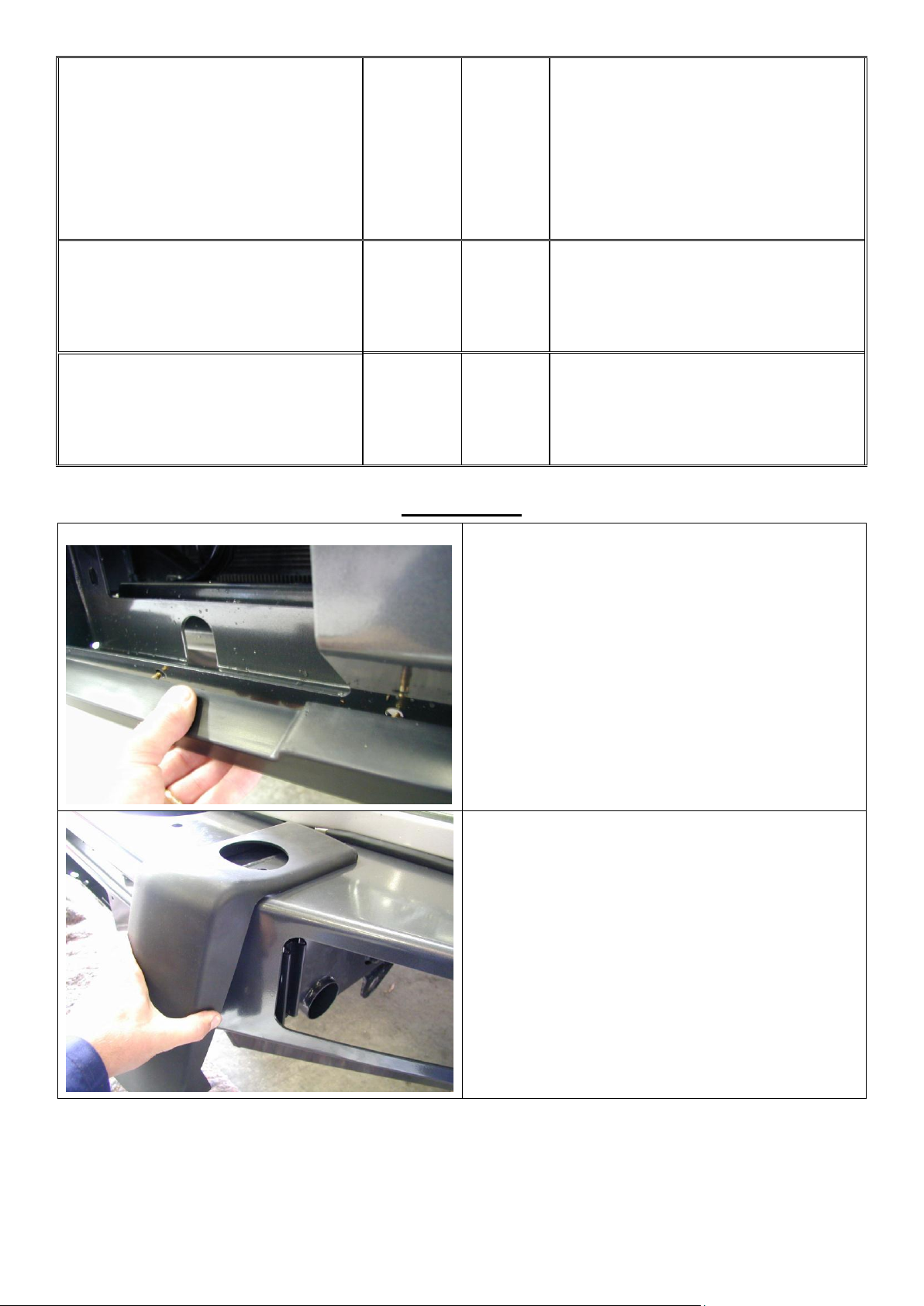
1. Position the lower buffer and assemble using
the M6 flange nuts. (Do not over tighten)
1. Fit the buffers. Buffer studs fit through the
slots in the wings and the pan. Fasten
using M6 flange nuts.
Note: This applies to both blank buffers and for
those with the hole for optional frame.
CAUTION: DO NOT OVER TIGHTEN THE M6
NUTS AS YOU RISK PULLING THE STUDS OUT
OF THE BUFFERS.
18/04/13 Page 4 of 9 3786418
2. Fit cage nuts to the bull bar. M10’s to
the six square holes in the upright and
M6’s in the four square holes in the
lower part of the pan. Also fit the M12
cage nuts to the captive nut assembly.
3. Remove front bumper cover from
vehicle.
4. Remove front bumper reinforcing bar.
5. Remove side bumper supports from
both guards.
NOTE: Retain the 8 flange nuts removed
for fitment of the bull bar chassis mount.
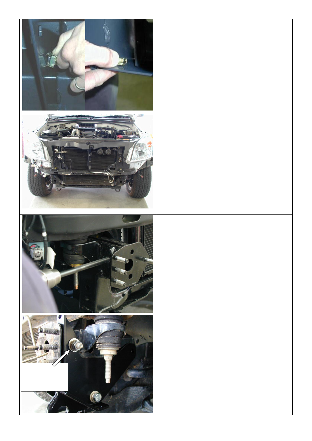
6. Using the 13mm drill bit, drill out the M8
captive nut in the top of the chassis on
both sides of the vehicle.
7. Fit the chassis mount braces to the
vehicle using the M12 x 30mm fine
pitched bolt, M12 spring and flat
washers supplied in the lower hole. Use
a M12 flat washer as a spacer between
the brace and the chassis at the upper
hole and fix with a M12 x 40mm bolt
M12 spring and flat washers and M12 x
1.75 nut. Do not tighten the bolts.
Use a M12 flat
washer as a spacer
between chassis
and bracket.
18/04/13 Page 5 of 9 3786418
8. Insert the captive nut assembly through
the front of the chassis and line it up
with the hole at the end of the mount
brace. Fix in place with the M12 x 1.75
x 40mm bolt, M12 flat and spring
washers. Break off the end of the
captive nut plate. Do not tighten yet.
9. Hold the 8mm spacer against the
chassis mount brace forward facing
surface and position the brace so that
the spacers sit just below the surface of
the chassis front face. Tighten the bolts.
10. Fix the chassis mount bracket to the
chassis mount brace using M12 x
40mm bolts, M12 spring and flat
washers, the 8mm spacers and M12 x
1.75 nuts. Tighten bolts.
CAUTION: when fitting the Chassis
mounting bracket carefully bend the air-
conditioning pipe out of the way.
Position brace so spacer
won’t protrude from the
chassis forward surface
18/04/13 Page 6 of 9 3786418
BEFORE ROTATION
AFTER ROTATION
11. For ease of access the winch gearbox
handle needs to be rotated. To do this
undo all the cap screws and carefully lift
the gearbox clear of the winch body so
as not to damage the gasket. (Do not
lift the gearbox more than a couple
of millimetres) Rotate the gearbox
anti-clockwise three hole spaces. Re-fit
the caps-crews.
12. Remove the three screws from the
control box and remove the cover.
13. Replace the two cables marked “A” and
“F1” and replace them with the two
cables (BLB560) supplied with the
fitting kit. Label the cables the same as
the original to assist in the wiring of the
winch.
14. Place the winch on a table with the feet
facing up and using an assistant,
carefully lift the bar on top of the winch.
15. Attach the winch to the bar using two 1
½” x 3/8” bolts from the winch fitting kit,
3/8” spring washer and 3/8” flat
washers in the top holes.
NOTE: Winch must be assembled so that
the wire rope spools from the bottom and
the gearbox is on the passenger side.
16. Position the roller fairlead, and remove
the circlips from the lower of the verticle
rollers and push the pins up to give
access to the lower bolts.
17. Fix the roller fairlead to the bar using
the 1 ¾” x 3/8” bolts, spring and flat
washers.
A
F1
18/04/13 Page 7 of 9 3786418
18. Fit the control box bracket to the bar
using two M8 x 20mm bolts, M8 flat
washers and M8 flange nuts.
19. Fit the control box to the control box
bracket and connect the power cables
to the winch as per the winch
instructions.
20. Connect the ground wire to the tension
bar of the winch.
CAUTION: Cable-tie all cables together
and keep all cables clear of sharp edges
and all moving parts.
With winch
Without winch
21. Place the double-sided tape along the
top edge of the licence plate. Using the
original licence plate screws and M6
flange nuts supplied in the fitting kit,
attach the licence plat to the bar.
22. Mask the area around the headlight and
the front guard and paint the lower
section under the front guard black.
Paint this section on both sides black.
23. With the help of an assistant position
the bar on the chassis bracket and fix
with six M10 x 30mm bolts, M10 spring
and flat washers.
Do not tighten the bolts yet.
18/04/13 Page 8 of 9 3786418
If fitting Top Tube
24. Attach the tube to the bar by pushing
through the holes in the buffers, fix
using two M12 x 1.75 x 40mm bolts, ½”
flat and spring washers.
25. Position the bar so that there is an even
gap along the headlights and the
guards of 25mm. tighten all the bolts.
25mm gap
26. With the bar in position drill a 10mm
hole through the upright on both sides
using the hole in the chassis bracket as
a guide.
27. Fix in place using two M10 x 30mm
bolts, M10 spring washers, M10 Flat
washers and M10 x 1.5 nuts.
28. Remove the front stone tray from the
vehicle and remove the tags at the front
of the tray. Refit the stone tray fixing in
place with the rear bolts only.
Attach tube
inside wing
NOTE:
Torque these M12 fasteners to
44Nm only (Critical)
18/04/13 Page 9 of 9 3786418
29. Fit the bull bar stone tray by sliding the
tray under the front of the vehicles
original stone tray and fixing in place
with the original bolts from the vehicles
stone tray.
30. Fit the front of the stone tray to the bull
bar with four M6 x 16mm bolts, M6
large panel washers and M6 spring
washers.
31. Fit the washer bottle guard with five M8
x 25mm black bolts, M8 black flat
washers and M8 flange nuts.
32. After fitting the washer bottle guard, trim
the plastic inner guard liner so that it
doesn’t sit below the line of the washer
bottle guard
33. Attach the inner guard to the washer
bottle guard with cable ties.
Repeat step 33 for the opposite side.
34. Assemble and install combination light
surrounds (p/n 3163015) as per
instructions no. 3786421 supplied with
surround kit. Note: Optional fog lamps
can be installed at this point as per
fitting instruction no. 3783315 supplied
with fog lamp kit no. 6821201.
35. Wire the combination lamp to the
vehicles indicator and clearance lamps.
CAUTION: Cable-tie all cables together
and keep all cables clear of sharp edges
and all moving parts.
When finished make sure that all bolts are tightened and that all wiring is clear of hot, sharp and
moving parts.
Also supplied in the kit are two 3/8” rubber grommets and two 16mm plugs. The rubber
grommets are for the two holes in the top pan if lights are being fitted. The two plastic plugs are
for the holes in the top surface of the wings if no CB aerials are going to be connected.

Other ARB Automobile Accessories manuals

ARB SA290AA290 User manual

ARB

ARB SA290AA290 User manual

ARB Air Locker RD204 User manual

ARB

ARB Air Locker RD204 User manual

ARB 3432200 User manual

ARB

ARB 3432200 User manual

ARB Airlocker RD137 User manual

ARB

ARB Airlocker RD137 User manual

ARB Airlocker RD214 User manual

ARB

ARB Airlocker RD214 User manual

ARB AIRLOCKER RD136 User manual

ARB

ARB AIRLOCKER RD136 User manual

ARB Airlocker RD140 User manual

ARB

ARB Airlocker RD140 User manual

ARB 3540320 User manual

ARB

ARB 3540320 User manual

ARB Airlocker RD143 User manual

ARB

ARB Airlocker RD143 User manual

ARB Airlocker RD232 User manual

ARB

ARB Airlocker RD232 User manual

ARB Flinders User manual

ARB

ARB Flinders User manual

ARB Airlocker RD205 User manual

ARB

ARB Airlocker RD205 User manual

ARB AIRLOCKER RD208 User manual

ARB

ARB AIRLOCKER RD208 User manual

ARB 3434040 User manual

ARB

ARB 3434040 User manual

ARB 3217300 User manual

ARB

ARB 3217300 User manual

ARB RD101 User manual

ARB

ARB RD101 User manual

ARB Airlocker RD152 User manual

ARB

ARB Airlocker RD152 User manual

ARB AIRLOCKER RD128 User manual

ARB

ARB AIRLOCKER RD128 User manual

ARB RD151 User manual

ARB

ARB RD151 User manual

ARB AIRLOCKER RD170 User manual

ARB

ARB AIRLOCKER RD170 User manual

ARB 10900013 User manual

ARB

ARB 10900013 User manual

ARB 3414020 User manual

ARB

ARB 3414020 User manual

ARB 3414470 User manual

ARB

ARB 3414470 User manual

ARB 6174921 User manual

ARB

ARB 6174921 User manual

Popular Automobile Accessories manuals by other brands

AMP Research PowerStep 77122-01A installation guide

AMP Research

AMP Research PowerStep 77122-01A installation guide

Mitsubishi MOTORS ED-330BE-R1 Service manual

Mitsubishi MOTORS

Mitsubishi MOTORS ED-330BE-R1 Service manual

Stealth Hitches SHR31016 installation instructions

Stealth Hitches

Stealth Hitches SHR31016 installation instructions

travall TDG 1529 Fitting instructions

travall

travall TDG 1529 Fitting instructions

NavLinkz RL3-LR17 manual

NavLinkz

NavLinkz RL3-LR17 manual

Prorack K464 Fitting instructions

Prorack

Prorack K464 Fitting instructions

Jaeger 21500638 Fitting instructions

Jaeger

Jaeger 21500638 Fitting instructions

Legend LK1-121-03 installation guide

Legend

Legend LK1-121-03 installation guide

AMP Research BedStep 75325-01A quick start guide

AMP Research

AMP Research BedStep 75325-01A quick start guide

POOL-LINE 110068 quick start guide

POOL-LINE

POOL-LINE 110068 quick start guide

Federal Signal Corporation DFC-WC-DUR21 manual

Federal Signal Corporation

Federal Signal Corporation DFC-WC-DUR21 manual

Discount Car Stereo A2DIY-MBCD quick start

Discount Car Stereo

Discount Car Stereo A2DIY-MBCD quick start

Whispbar K742W Fitting instructions

Whispbar

Whispbar K742W Fitting instructions

Nav TV BMW56-CAN manual

Nav TV

Nav TV BMW56-CAN manual

Mazda A2DP owner's manual

Mazda

Mazda A2DP owner's manual

Westin 46-23995 installation instructions

Westin

Westin 46-23995 installation instructions

Mennekes AMTRON Xtra User's operation manual

Mennekes

Mennekes AMTRON Xtra User's operation manual

Curtis XP 900 Installation & owner's manual

Curtis

Curtis XP 900 Installation & owner's manual

manuals.online logo
manuals.online logoBrands
  • About & Mission
  • Contact us
  • Privacy Policy
  • Terms and Conditions

Copyright 2025 Manuals.Online. All Rights Reserved.