ARB AIRLOCKER RD109 User manual
RD109
DANA 44, 35 SPLINE,
3.92 & UP
AIR OPERATED
LOCKING DIFFERENTIAL
INSTALLATION GUIDE

No liability is assumed for damages resulting in the use of the information contained herein.
ARB Air Locker Air Operated Locking Differentials and Air Locker are trademarks of ARB Corporation Limited.
Other product names used herein are for identification purposes only and may be trademarks of their respective owners.
ARB 4x4 ACCESSORIES
Corporate Head Office
42-44 Garden St Tel: +61 (3) 9761 6622
Kilsyth, Victoria Fax: +61 (3) 9761 6807
AUSTRALIA
3137
Australian enquiries sales@arb.com.au
North and South American enquiries sales@arbusa.com
Other international enquiries exports@arb.com.au
www.arb.com.au
Table of Contents:
1
1 Introduction
3
1.1
Pre-Installation Preparation
3
1.2
Tool-Kit Recommendations
4
2 Removing the Existing Differential
5
2.1
Vehicle Support
5
2.2
Differential Fluid Drain
5
2.3
Disconnecting the Axles
6
2.4
Marking the Bearing Caps
6
2.5
Checking the Current Backlash Amount
7
2.6
Removing the Differential Center
8
3 Installing the Air Locker
10
3.1
Insuring Adequate Oil Drainage
10
3.2
Installing the Carrier Bearings
11
3.3
Approximate Backlash Shimming
12
3.4
Mounting the Ring Gear
15
3.5
Drilling and Tapping the Bulkhead Port
16
3.6
Assembling the Seal Housing
17
3.7
Pre-Load Shimming
18
3.8
Reinstalling the Bearing Caps
21
3.9
Checking the Backlash
22
3.10
Setting Up the Bulkhead Fitting
23
3.11
Profiling the Seal Housing Tube
25
4 Installing the Air System
26
4.1
Mounting the Solenoid
26
4.2
Running & Securing the Air Line
28
4.3
Connection to the Bulkhead Fitting
29
5 Mounting & Connecting the Electrical System
31
5.1
Mounting the Actuator Switch(es)
31
5.2
Wiring the Actuator System
32
6 Testing & Final Assembly
36
6.1
Leak Testing
36
6.2
Reinstalling the Axles
36
6.3
Testing the Air Locker Actuation
37
6.4
Re-Sealing & Filling the Differential
37
6.5
Post-Installation Check List
38
7 Parts List
39
7.1
Exploded Assembly Diagram
39
7.2
Itemized Parts List
40

2

1 Introduction
3
IMPORTANT :
BEFORE ATTEMPTING TO DISMANTLE YOUR VEHICLE FOR THIS
INSTALLATION, PLEASE READ THIS INSTALLATION GUIDE IN ITS
ENTIRETY, AS WELL AS ALL APPLICABLE SECTIONS OF YOUR
VEHICLE MANUFACTURER’S SERVICE MANUAL.
1.1 Pre-Installation Preparation
This booklet is to be used in conjunction with your vehicle
manufacturer’s service manual. ARB endeavors to account for every
possible variation in vehicle model when publishing its installation
guides, and guides are updated regularly as new model information
becomes available, however, the rapid and globally varied release of
some vehicles makes it difficult to insure that your vehicle model has
been accurately accounted for. In the case of any technical
discrepancies between this guide and your service manual, we
strongly advise that you adhere to the specifications and techniques
as documented in your service manual.
Although your ARB Air Locker comes complete with all the step by
step instructions you will need to supplement your vehicle
manufacturer’s service manual and install your new differential, ARB
recommends that you have your Air Locker installed by a trained
professional. Many ARB distributors around the world have been fully
instructed in Air Locker installations by ARB, and have gained a wealth
of experience and skill from years of performing similar installations.
Once you begin this installation your vehicle will be immobile until all
steps of the installation are complete. Make sure your Air Locker kit is
the correct model for your vehicle and that it contains all of the parts
listed on back cover of this booklet. Also be sure you have
appropriately equipped yourself with all the necessary tools, parts, and
materials to complete this installation (see section 1.2 Tool-Kit
Recommendations), and that you have allowed for an appropriate
amount of vehicle down time.
HINT : Place a mark inside each of the
symbols as
you complete each step. It is very important NOT to
miss any of the steps!

1 Introduction
4
1.2 Tool-Kit Recommendations
Below is a list of tools and supplies you may need to complete this
installation. Requirements for your vehicle may vary. Please consult
your vehicle service manual for additional recommendations.
1.2.1 Tools
Standard automotive sizes (metric and/or imperial) of sockets,
wrenches, Alan keys, and drills.
A dial indicator or other suitable measuring tool for checking ring &
pinion backlash.
A standard automotive feeler gauge.
A razor knife to cut the nylon tubing.
A differential housing spreader, to facilitate removal of the carrier.
(not required on aluminum housings)
A torque wrench. (See vehicle service manual for required torque
range.)
A lubricant drain reservoir.
Suitable measuring tools to measure a differential for pre-load
and/or backlash shimming. (See Section 3.3)
A 11.2mm [7/16”] drill and ¼” NPT tap for bulkhead fitting
installation.
An automotive bearing puller (2 jawed is recommended) or a
differential carrier bearing puller.
A bearing press or arbor press.
1.2.2 Supplies
Thread lubricant/sealant compound for pressure fittings
(e.g., LOCTITE #567 Teflon paste)
Thread locking compound (e.g., LOCTITE #272)
Either a replacement gasket, or gasket sealant, for your differential
cover.
A sufficient volume of differential oil to completely refill your
housing. (see the ARB Air Locker Operating and Service Manual
for recommended lubricants)
A soap and water mixture to test for air leaks.
2 Removing the Existing Differential
5
2.1 Vehicle Support
Safely secure the vehicle on a hoist. We recommend supporting
the vehicle on a chassis hoist to keep the differential area at a
convenient working height and to leave the wheels and axles free
to be rotated and removed.
Once supported off the ground, release the parking brake and
leave the vehicle in neutral. Chock the wheels if necessary.
2.2 Differential Fluid Drain
HINT : This is a good time to check for metal particles in
your oil, on your drain plug, or in the bottom of the
housing which may indicate a worn bearing or
differential component.
Clean around the differential cover plate seal to prevent dirt from
entering the differential.
Position a fluid drain reservoir under the differential and loosen all
differential cover plate retaining bolts.
If a drain plug exists, remove it and completely drain all differential
oil from the housing.
If no drain plug exists then the oil can be drained by loosening the
cover bolts and gently prying the cover away at the bottom until oil
runs out.
HINT : If a drain plug does not exist then it would be a good
idea to drill and tap for a tapered oil drain plug to assist
with future oil changes.
Once drained, remove the differential cover plate.
2 Removing the Existing Differential
6
2.3 Disconnecting the Axles
IMPORTANT :
Collision damage or heavy off-road use of your vehicle in the past may
have resulted in some degree of bending in the axle. Any misalignment
of the axle tubes may result in excessive wear and/or failure of your
differential and axle shafts. ARB strongly recommends that you have
your axle assembly inspected for concentricity and straightness before
installing your Air Locker.
Remove the wheels, and brakes according to your vehicle
manufacturer’s service manual.
Disconnect the drive shaft from the differential drive flange.
Remove both axle shafts according to your vehicle manufacturer’s
service manual.
NOTE : The axle oil seals are delicate and can be easily
damaged. Support the weight of the axle shaft when
drawing them out of their sockets in the housing.
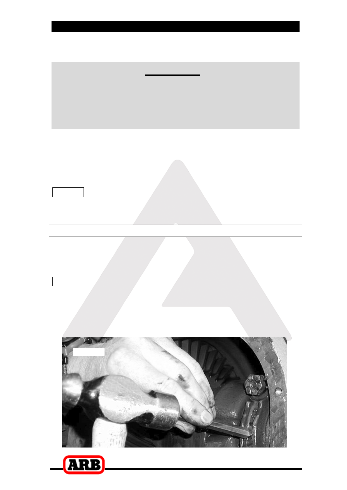
2.4 Marking the Bearing Caps
Using a pointed center punch, gently mark the bearing caps in a
way that will enable you to know which cap is ‘LEFT’ and which cap
is ‘RIGHT’, which way is ‘UP’ and which way is ‘DOWN’. (Fig.1.)
HINT : Many installers choose to make one punch mark on
the left hand side of the left hand bearing cap and one
similar punch mark on the housing at close proximity to
the cap mark. The right hand side is then designated
with two punch marks on the right hand side of the cap
and two similar punch marks on the housing.
Figure 1.
2 Removing the Existing Differential
7
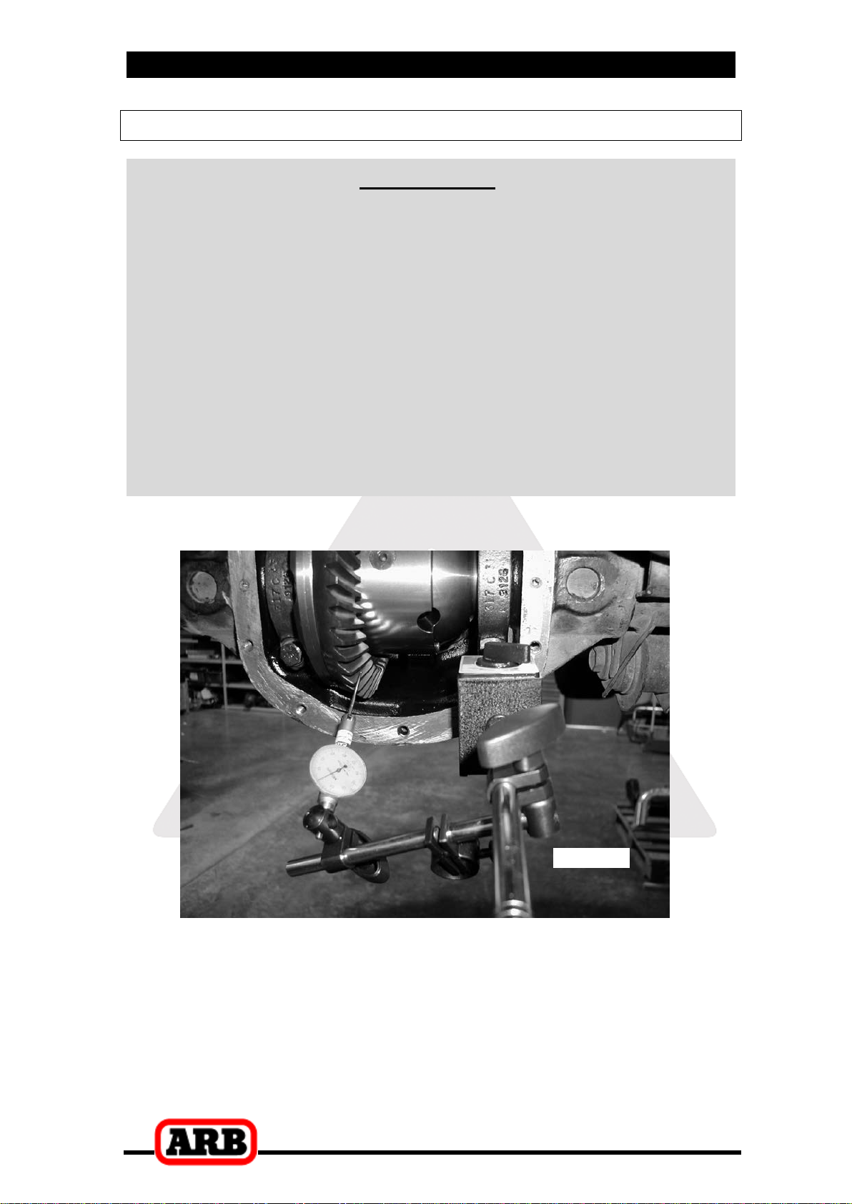
2.5 Checking the Current Backlash Amount
IMPORTANT:
This step is a precautionary measure recommended by ARB due
to the fact that some after market ring and pinion sets have been
manufactured to run with different backlash settings than those
specified by your vehicle manufacturer. Although ARB must
recommend you set backlash according to your service manual
guidelines, we also advise that you compare the backlash
measurements taken here to the recommended backlash settings
in your vehicle service manual. Measurements found to be
outside of your service manual recommendations may indicate
the need to deviate from those settings in order to achieve quiet
running with a good contact mark.
Refer to your vehicle service manual or your local authorized
ARB installer for more information.
Set a depth indicator on one of the ring gear teeth as in figure 2.
Figure 2.
While supporting the pinion gear by holding the drive shaft flange,
rotate the differential in both directions while observing the
maximum variation in depth from the indicator (i.e., the highest
value minus the lowest value). This value is referred to as the ring
and pinion backlash.
Rotate the differential center 90°and measure again for accuracy.
Record the average of all measurements.
2 Removing the Existing Differential
8
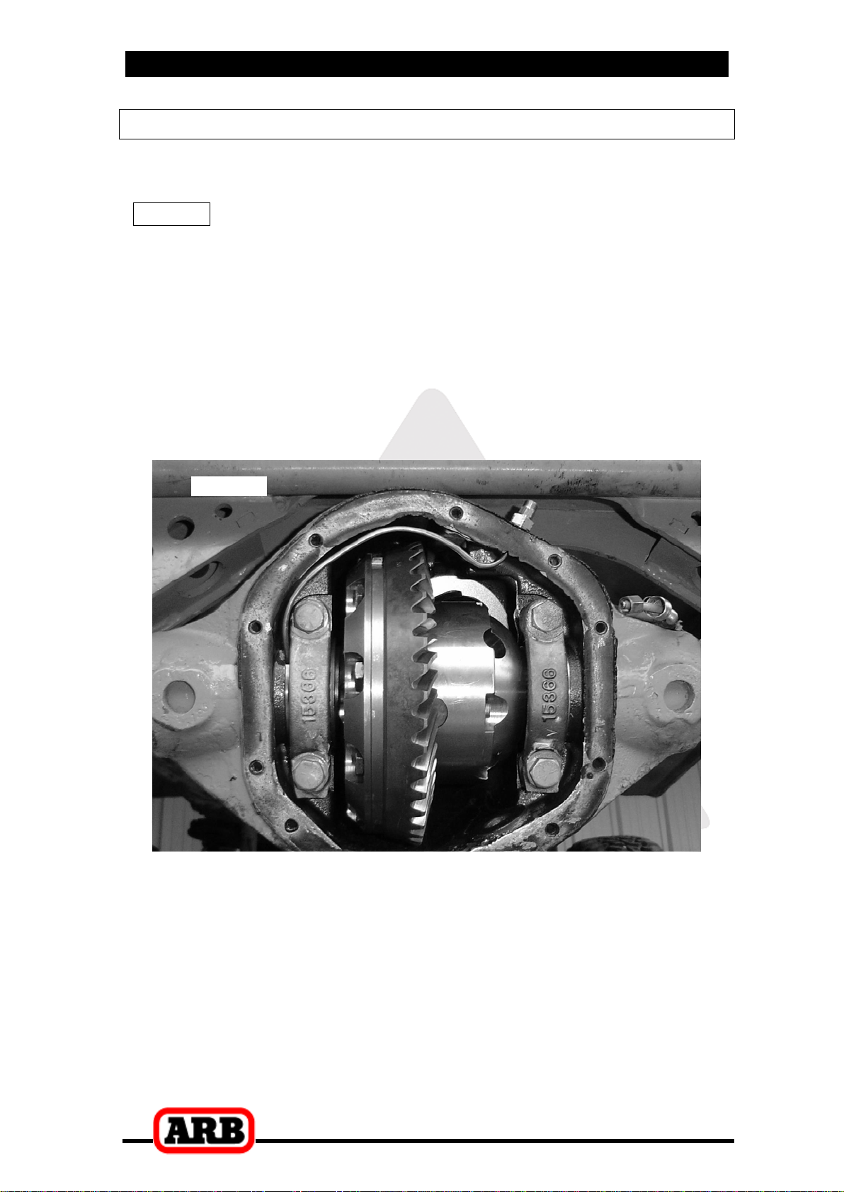
2.6 Removing the Differential Center
IMPORTANT:
YOU MUST SPREAD THE HOUSING ON CAST IRON MODELS
Spreading the differential housing with a differential case
spreader is a step which is critical to set up bearing pre-load
on cast iron differential housings (See Figure 3.). Improper
pre-load will result in undue bearing wear, increased stresses
in the differential center, increased running noise, and
ultimately, ring and pinion gear damage.
Remove both bearing caps.
Carefully spread the housing (Fig.3.) enough to remove the
differential center. (Refer to your vehicle’s service manual).
NOTE : Do not spread the housing more than 0.50mm [0.020”].
HINT : Be sure not to mix up the left and right hand bearing
cups. Later it will be necessary to know which cup
came from which side.
Once the housing has been adequately spread, the differential may
be removed by pulling forward on the differential carrier.
Figure 3.
2 Removing the Existing Differential
9
NOTE : The differential center is heavy and quite difficult to
handle when covered in oil. Take care not to drop it.
Relieve any tension on the spreader immediately after the
differential has been removed.
NOTE : Some Dana 44 type differentials now come from the
factory equipped with an OE master shim on the
outside of each bearing cup to setup bearing preload.
This system is used instead of using a shim pack
underneath each bearing cone. Do not mix up which
side of the differential the OE master shims came
from, as they must be re-used on assembly.
3 Installing the Air Locker
10
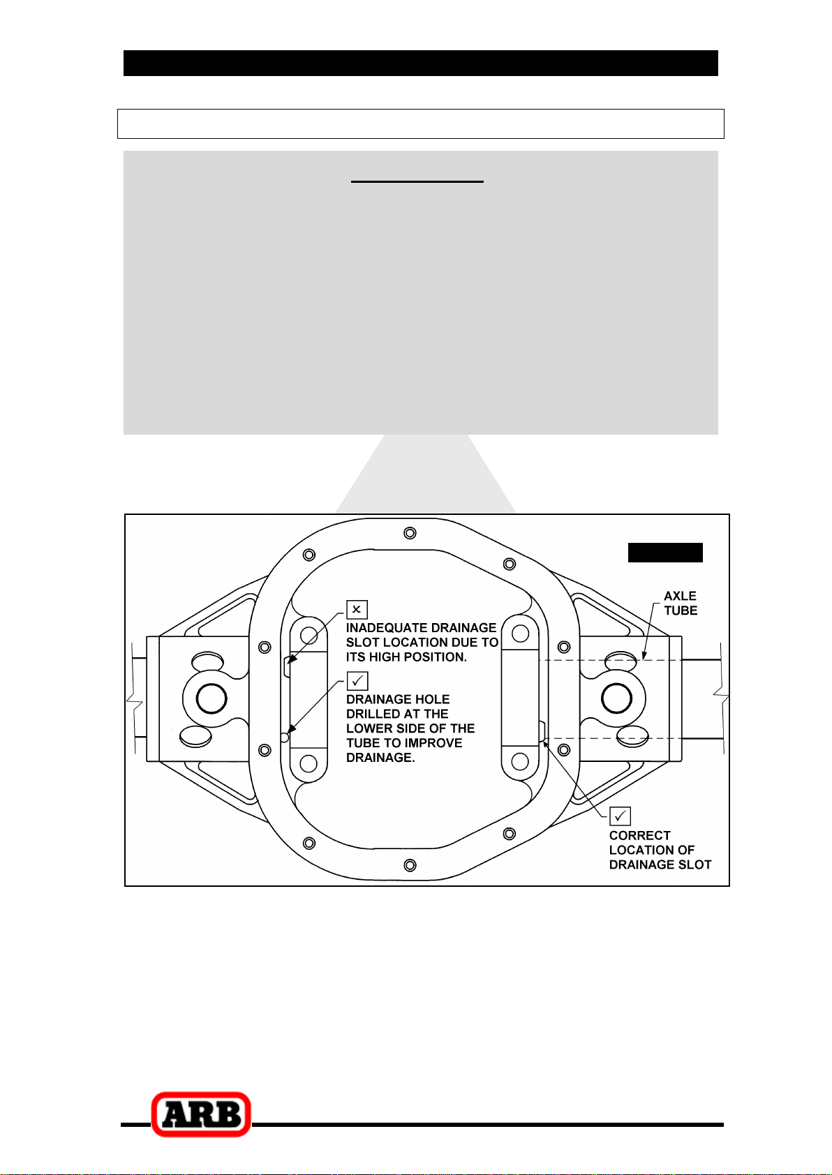
3.1 Insuring Adequate Oil Drainage
IMPORTANT:
Some Salisbury axles were manufactured with poor oil drainage
between the axle tubes and the differential housing. This can
often result in one of the axle tubes filling up with differential oil
while running. In most cases this will result in a blocked air vent
which will cause the differential housing to pressurize and expel
oil from the axle seals at the wheels or force oil into the air
system of the Air Locker, eventually expelling oil at the solenoid
valve. This is a design flaw which was corrected by most
automakers in the later releases of their axle assemblies. If no
lower drainage point is present in the differential housing then it
is critical that you modify the housing to include one.
Inspect the differential housing for the presence of adequate
drainage in both axle tubes (refer to Fig.4.).
Figure 4.
If no drainage slot is present at the left-hand side (refer to Fig.4.) of
the housing at all, then a slot will have to be created as clearance
for the seal housing tube (Refer to Section 3.8 Reinstalling the
Bearing Caps).
If drainage exists but is inadequate then a slot or hole should be cut
into the housing on the lower side of the tube(s) to allow oil out of
the axle tube area.
3 Installing the Air Locker
11
NOTE : Make sure any grinding dust, filings or drill chips left
behind by cutting the drainage slots is completely
cleaned out of the housing.
Check that the axle air vents are clear and working correctly.
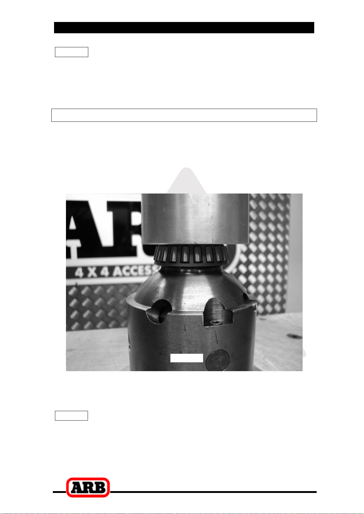
3.2 Installing the Carrier Bearings
Apply a thin film of high pressure grease to both bearing journals of
the Air Locker to prevent seizing.
Using a bearing press or arbor press, press one of the bearing
cones (supplied with the Air Locker kit) onto one bearing journal of
the Air Locker (refer to Figure 5.) until the bearing seats firmly
against the bearing journal shoulder.
Figure 5.
Invert the Air Locker and press the other tapered roller bearing
cone onto the opposite bearing journal of the differential carrier until
the bearing seats firmly against the bearing journal shoulder.
NOTE : Do not add any shims between the bearings and the
bearing seat. Shimming of the Air Locker will be
performed with the supplied shim kits and/or the OE
master shims (if any) on the outside of the carrier
bearings.

3 Installing the Air Locker
12
3.3 Approximate Backlash Shimming
In order to reproduce a similar pre-load and ring and pinion backlash
in your Air Locker to that of your original differential, measurements
need to be taken so that a shim thickness can be calculated.
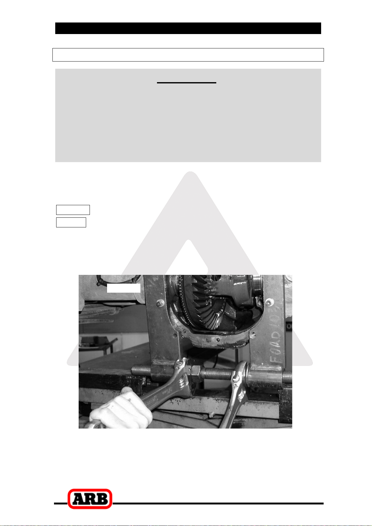
Secure the original differential to a work bench.
Remove the bolts that hold the ring gear in place.
Using a plastic or copper hammer, tap in a circle around the ring
gear to separate it from the differential carrier.
Figure 6.
Assemble the original bearing cup onto the cone of the right-hand
side of the original differential carrier.
Using a caliper or similarly accurate measurement method
(i.e., able to take accurate measurements within 0.04mm [0.0015”]),
measure the distance from the shoulder of the outer face of the
bearing cup to the ring gear mounting face (shown as ‘A’ in Figure
6.) and record this measurement as ‘A’.

3 Installing the Air Locker
13
NOTE : Be sure to measure using the bearing cup that
originally came off of the right-hand side.
Assemble the new bearing cup and ARB master shim (supplied
with your Air Locker kit) onto the right-hand side of the Air Locker
(as shown in Fig. 7.) and measure the total distance ‘C’.
NOTE : The shim pack ‘B’ should not be installed at this time.
NOTE : The OE master shim (if present) should not be
included in measurement ‘C’.
Figure 7.
Record this measurement as ‘C’.
3 Installing the Air Locker
14
The thickness of the shim pack ‘B’ should make the distance ‘C’ on the
Air Locker closely match the distance ‘A’ on the existing differential
(within 0.1mm [0.004”] ).
Use the following calculation to find the desired thickness of ‘B’:
A – C = B (Replacement Shim Pack)
HINT : If your calculations are correct then the following
equation will also be true:
A – B – C = ZERO
Select shims from the shim kit supplied with your Air Locker to
make the thickness ‘B’ as determined above.
Place this shim pack between the ARB master shim and the
bearing cup.
Re-measure the new distance ‘C’ from the Air Locker (now
including the shim pack ‘B’) to make sure that it matches ‘A’ on the
original differential.
NOTE : NEVER machine the Air Locker.

3 Installing the Air Locker
15
3.4 Mounting the Ring Gear
IMPORTANT:
Dana 44 ring gears may use either 3/8”, 7/16”, or 1/2” bolts.
For 7/16” bolts re-drill Air Locker flange to 11.5mm [29/64”].
For 1/2” bolts re-drill Air Locker flange to 13.0mm [33/64”].
Apply a thin film of high pressure grease to the ring gear shoulder
of the Air Locker to prevent seizing.
Thoroughly clean any thread locking compound or other foreign
matter from the holes of the ring gear, the threads of the ring gear
bolts, and the mating surfaces between the ring gear and the Air
Locker flange.
HINT : Stoning the ring gear mounting face before installation
will remove any high spots around the threads.
Heat the ring gear to between 80 and 100°C [175 - 212°F] in hot
water or in an oven to slightly expand the gear and facilitate
assembly.
NOTE : NEVER HEAT GEARS WITH A FLAME! This could
damage the hardened surface of the gear and result in
premature wear or failure.
Dry the gear and bolt holes with compressed air (if wet).
Install the ring gear onto the Air Locker by aligning the bolt holes
and then gently tapping it around in a circle with a soft mallet.
Avoid using the bolts to pull down the ring gear as this puts excess
strain on the bolts and the differential flange.
Apply a thread locking compound to the thread of each ring gear
bolt before inserting it. Do not apply threading compound directly
into the threaded hole as this could prevent the bolt from reaching
its full depth.
Tighten the ring gear bolts in a star pattern with a torque wrench
according to your vehicle manufacturer’s specified torque.
3 Installing the Air Locker
16
3.5 Drilling and Tapping the Bulkhead Port
An airline port must be drilled and tapped through the differential
housing to mount the bulkhead fitting into.
NOTE : Higher ratio gearing uses deeper (thicker) ring gears
with teeth that extend much further. Make sure the
intended hole location is far enough away from the
ring gear teeth that the air line will not be at risk of
contact with the current or future ring gears.
Mark a position on the top of the outside shell of the differential
housing that is about 40mm [1.5”] in from the bolt face where the
inspection cover sits and located as shown in the completed
installation in Figure 8. The bulkhead position must allow the seal
housing tube (assembled at a later time) to be clear of the ring gear
position.
Figure 8.
Cover the drive pinion and axle tube areas with a rag to protect
them from metal filings.
Drill through the housing square to the outside surface using a
11.2mm [7/16”] drill.
Tap the hole from the outside using a ¼” NPT pipe tap.
Remove any sharp edges from the hole that may chip-off and fall
into the housing.
Carefully remove the rags and inspect with a service light inside the
housing to insure no metal filings are left behind.
3 Installing the Air Locker
17
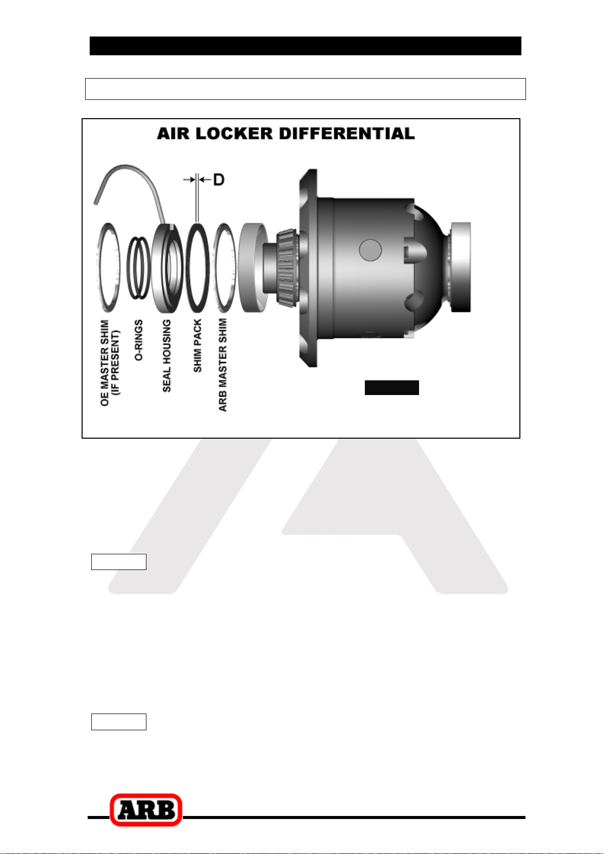
3.6 Assembling the Seal Housing
Figure 9.
Make sure the grooves and airway of the seal housing are clean
and free from any contaminants (e.g. water, dirt, metal filings, etc.).
Inspect the seal housing O-rings (supplied) for dirt, damage or
other conditions which might cause leaks.
Generously lubricate the O-rings with oil prior to assembly, then
insert them into the grooves of the seal housing.
NOTE : When assembling the O-rings, be careful not to leave
them twisted when seated in the grooves as this could
cause excessive wear and leakage.
Lubricate the seal housing running surface on the Air Locker carrier
with oil. Assemble a bearing cup onto the left-hand side of the Air
Locker.
Assemble one of the two ARB master shims (included with the Air
Locker shim kit) onto the stepped face of the seal housing with the
rounded edge of the shim facing out.
NOTE : No shims other than the single ARB master shim
should be assembled onto the seal housing at this
time.

3 Installing the Air Locker
18
Carefully install the seal housing (ARB master shim towards the
center) by sliding it all of the way onto the bearing journal with a
gentle twisting motion. This will allow the O-rings to engage gently.
3.7 Pre-Load Shimming
In order to pre-load the tapered roller bearings in your Air Locker,
measurements need to be taken so that a value can be calculated for
the shim thickness ‘D’ in Figure 9.
IMPORTANT NOTE FOR OE MASTER SHIM TYPE
DANA 44 SETUP:
Grind or cut a notch into the left-hand factory shim as clearance for the
seal housing tube at final assembly, as per Figure 10.
Insert the right hand OE master shim between the ARB master shim
and the axle housing, and the left hand OE master shim between the
seal housing and the axle housing making sure to align the notch with
the notch in the axle housing and the seal housing tube.
All pre-load measurements and any required shimming should be
made between the seal housing and the left hand OE master shim.
Figure 10.
Insert and hold the Air Lockerinto the differential housing.
Insert the remaining ARB master shim from the Air Locker shim kit
between the right-hand bearing cup and the bearing seat of the
axle housing with the rounded edge of the ARB master shim facing
away from the center.
Insert the shim pack determined earlier as ‘B’ between the bearing
cup (right-hand side) and the ARB master shim.
Push (or lightly pry) the Air Locker hard across to the right-hand
side, and measure the maximum gap (also called the ‘end float’)
between the outside of the seal housing and the inside face of the
axle housing with an automotive feeler gauge. (Fig.11.)
Table of contents
Other ARB Automobile Accessories manuals


Popular Automobile Accessories manuals by other brands

DEFA
DEFA 411118 Fitting instructions

Mont Blanc
Mont Blanc FK93 Fitting instructions

Witter
Witter HY55U Fitting instructions

POOL-LINE
POOL-LINE 110050 Assembly instructions

Star Headlight & Lantern
Star Headlight & Lantern LCS850MG Installation and instruction manual

Jotto Desk
Jotto Desk 425-5595 quick start guide


