ArcOne 1000FcF Operator's manual

USER INSTRUCTION MANUAL
CarreraTM
ARCONE®
Helmet with
Auto-Darkening Filters
85 Independence Drive, Taunton, MA 02780
Tel: 508-884-9600 Toll Free: 800-223-4685
Fax: 508-884-9666
Please visit our website and register at
www.arc1weldsafe.com
CARRERA-01-UIf

- 1-
Preparations for Use
FI TERS:
Before you begin welding always inspect your filter to ensure it is not damaged. Check to
see if the filter protection plates (cover plates) are clean, clear, undamaged, and securely
attached to the helmet and covering the auto-darkening filter both front and rear.
To test your filter, prior to welding, direct the front of the filter to a bright source of light
then, using your fingers, rapidly cover and uncover the sensors. The filter will darken
momentarily. Another means of testing is to utilize a torch striker or TV or VCR remote.
These devices will also momentarily darken the filter. Once you are sure that the filter is
working properly you are now ready to begin welding.
WARNING, Never begin welding without first checking to see if the correct front
protection plate is in place (see Part Selection Guide section for part numbers),
the filter is secured properly in the filter holder, and the filter holder secured in the
helmet . Failure to protect the welding filter or install the filter/filter holder
correctly may cause damage and become a safety hazard should the UV/IR
protection be compromised from spatter or cracks from impact. DAMAGE
CAUSED BY ABUSE SUCH AS EXCESSIVE TEMPERATURES, CRACKS FROM
IMPACT, AND PITTING FROM SPATTER CAUSED BY POOR MAINTENANCE WI
VOID WARRANTY.
WE DING HE METS:
Before you begin welding make sure there is no damage to the helmet shell including, but
not limited to cracks, holes, and melting. Ensure that the springs holding the filter are not
broken or corroded. Do not use the helmet if any of these conditions exist and contact your
distributor for replacement parts.
WARNING, Secondary impact protection required. Other safety precautions such
as protective clothing, adequate ventilation, breathing protection, fire
extinguisher, and protection for co-workers, should also be considered.
Not for use in overhead welding.
WARNING, Materials which may come into
contact with the wearer’s skin could cause
allergic reactions to susceptible individuals.
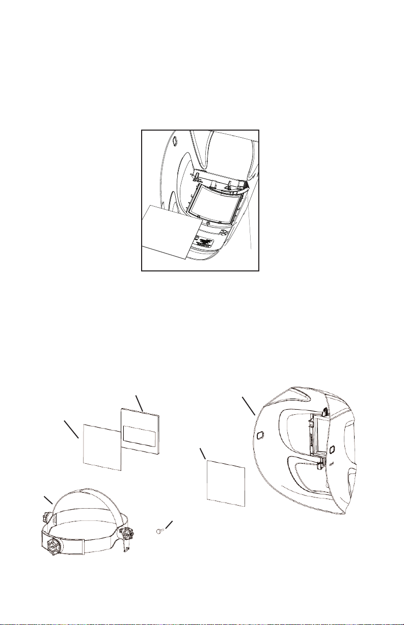
HEADGEAR:
Adjust the crown height via the pin hole adjustment
on the top strap of the headgear (see Figure1).
Adjust the circumference by turning the rear
knob while wearing.
Figure 1
Helmet Angle
Adjuster
TAB E OF CONTENTS PAGE
Preparations for Use 1
Technical Information/Use 2
Limitations of Use 3
Care and Maintenance 3
Spatter Protection 4
Parts Selection Guide 4
Filter Removal Instructions 5
Significance of Markings 5
Filter Specifications 6
Warranty and Service Information 7
Pin Hole
Adjustment
Adjust Fit: Push In, Turn, Release
Adjust Height: Snap
Out, Slide, Snap In

Technical Information/Use
FI TERS:
ARCONE
®auto-darkening filters protect the user against harmful ultra-violet and infrared
UV/IR rays, both in the dark and light state. No matter what shade the filter is set to
the UV/IR protection is always there. When used as instructed, you will never
burn your eyes due to optical radiation.
WARNING, Severe burns are possible with a damaged lens (cracks, pits, holes,
etc.). Do not use a damaged lens.
Note: Optical radiation may enter in from behind the helmet from other welders
welding in the immediate area.
Filter Specific Features
1000FcF and 4500V: Adjust Sensitivity, Shade, and Delay with the knobs on the back of
the filter (see Figure 2). Activate the Grind Mode by turning the Sensitivity knob counter-
clockwise past the white line; the knob will lock into Grind Mode. Deactivate the Grind
Mode by setting the Sensitivity to any setting above the white line. Other functions will not
work in Grind Mode.
1500V and 2000V: Adjust the Shade with
the knob on the outside of the helmet (see
Figure 3). Adjust Sensitivity and Delay
writh the knobs on the back of the filter
(see Figure 4). These models do not have
Grind mode.
2500V: Adjust Sensitivity, Shade, and
Delay with the knobs on the back of the fil-
ter. This model does not
have Grind mode (see Figure 5).
Technical Use (continued),
- 2-
GRIND
9
10
11
12
13
SH
A
D
E
9
10
11
12
13
SH
A
D
E
Figure 2: 1000FCF and 4500V Controls
LIGHT
DARK
SHADE KNOB
Figure 3: Outside Shade Control
Figure 4: 1500V and 2000V Controls Figure 5: 2500V Controls

- 3-
WE DING HE METS:
Welding helmets are designed to provide protection against UV/IR radiation around the
user’s face.
ARCONE
®welding helmets meet/exceed face coverage defined by CE
standards. Welding helmets are made of a durable, modern material capable of use in a
variety of environments.
imitations of Use
See also, Significance of Markings (page 5).
FI TERS:
ARCONE
®welding filters ARE NOT designed for oxy-acetylene, laser, or very low
amperage welding applications. Arc detection may be impaired due to amperage, distance
from the arc, welding current frequency, electrode type, shielding gasses, and lighting
conditions.
Do not weld with filter in the light state. If the filter fails to turn dark immediately stop use
and contact a service provider for help.
WARNING, Eye-protectors against high speed particles worn over standard
ophthalmic spectacles may transmit impacts, thus creating a hazard to the
wearer.
WARNING, Toughened mineral oculars shall only be used in conjunction with a
suitable backing ocular.
WE DING HE METS:
Not meant to protect against severe impact, explosives, fragments from grinding wheels,
and abrasive discs, and hazardous fluids.
Do not use this helmet without proper training from a certified welder or welding instructor.
Do not use this helmet in an excessive heat environment where the operation of the filter
becomes non-functional due to exceeding the temperature ratings of the electronic
components.
Care and Maintenance
NOTE: Replacement components must be used in accordance with these
instructions. Failure to use
ARCONE
®replacement components in accordance
with these instructions voids certification and warranty of this product.
FI TERS:
Filters require virtually no maintenance other than periodic cleaning when the lens, solar
panel, and/or sensors become dirty or clouded from smoke. Clean your filter by using
window cleaner or a mild soapy solution and a soft cloth or paper towel (do not immerse in
water or solution). Ensure that the sensors are kept clean and unobstructed. Change the
cover plates frequently.
WARNING, Replace scratched or damaged occulars
WE DING HE METS:
Welding helmets require virtually no maintenance other than periodic cleaning when dirty.
Clean your helmet by using a mild soapy solution and a soft cloth or paper towel (do not
immerse in water or solution).
WARNING, DO NOT throw or abuse the helmet. Doing so may crack the helmet
shell or filter, which may compromise the protection causing serious injury or
loss of life.
Store in an appropriate place to prevent damage when not in use (See Table 1:
Storage Temperature). Welding helmets may be stored and transported in their original
or similar packaging.

PO YCARBONATE PROTECTION (COVER) P ATE:
CAUTION,
Change cover plates when they lose flexibility and/or become bowed or
distorted. Clean with mild soapy solution including any build-up from the area where the
cover plate is retained. Discard if cleaning fails to improve visibility. Discard if cracks,
scratches, or other marks impair visibility.
Spatter Protection
Ensure the front cover plate is secure under all the tabs (see Figure 6) located inside the
CarreraTM
ARCONE
®Welding Helmet and within the area covered by the filter holder.
SPATTER DAMAGE IS NOT COVERED BY WARRANTY
All cover plates are 1 mm thick.
***To install, slide Polycarbonate under top tabs then push
underneath bottom tabs***
Parts Selection Guide
(see Filter Removal Diagram for replacing Filter and Cover Plates)
- 4-
Figure 6
Rotate Non-
Removable
Center Section
*Magnification Lens Options;
SSML or S911-MLHH depending
on filter
**Visit our website for the full
CarreraTM
ARCONE
® line of helmets
3-0100 CarreraTM
ARCONE
®
Helmet Shell with Center
Section (Black)**
04-HG
Headgear
Assembly
(Sweatband
not shown)
03-OP* Inside
Cover Plate
Auto-Darkening Filter
04-OP Outside
Cover Plate
Thumb Screw
Figure 7

- 5-
Significance of markings on
Auto-Darkening Filters:
Example: 4 / 9-13 AR 1/3/1 EN379
CE - European Conformity Mark
4 – Light Shade number
9 – Dark Shade range 1
13 – Dark Shade range 2
AR – Manufacturers mark
1 – Optical Class
3 – Diffusion of Light Class
1 – Variation in Luminous
Transmittance Class
EN379 – Standard for Auto-Darkening
welding filters
These models have been certified by:
DIN CERTCO
Gesellschaft für onformitätsbewertung mbH
Alboinstr. 56
D-12103 Berlin
Notified Body Number: 0196
Significance of CE Markings on
CarreraTM
ARCONE
® Welding Helmet**:
Example: AR EN 175 –F CE
AR - Company Identification Mark
EN 175 - CE Welding Helmet Standard
-F – Impact Class,
CE – European Mark
This model has been certified by:
INSPEC
56 Leslie Hough Way
Salford
Greater Manchester
M6 6AJ, England
Notified Body Number: 0194
Filter Removal Instructions
Removable Filter Holder
1. Grab filter by top and bottom edge
2. Pull up on bottom edge of filter and slide out of
the bottom of the filter holder (see Figure 8)
Helmet impact rating Z87+ with Thumb Screw
installed. Helmet rating Z87 without thumb
screw. For Z87+ make sure Filter Holder Center
Tab is secured to the Welding Helmet Centering
Pin with Thumb Screw
(See Figure 9). Do not over tighten.
Critical Installation Warning!
Figure 8
Figure 9
Slide
Note: In situations where protection against high speed particles at extreme
temperatures is required, use only eye-protectors with the letter T immediately
following the impact class letter, i.e., -FT, BT or AT. If the impact class letter is
not followed by the letter T then the eye protector shall only be used against
high speed at room temperature.

- 6-
Table 1: Filter Specifications
1000FcF 1500V 2000V 2500V 4500V
Viewing Area
(mm2)3864 4416 4704 4704 4752
Filter Size (mm) 90x110 90x110 90x110 90x110 90x110
ARC Sensing Two sensors Two sensors Two sensors Two sensors Four sensors
Sensitivity
Control Variable Variable Variable Variable Variable
Switching Time
(seconds)
1/10,000
(0.1ms)
5/10,000
(0.5ms)
1/10,000
(0.1ms)
1/10,000
(0.1ms)
1/10,000
(0.1ms)
Primary Power Solar Cells Solar Cells Solar Cells Solar Cells Solar Cells
Back-up
Power
Lithium
Battery
Lithium
Battery
Lithium
Battery
Lithium
Battery
Lithium
Battery
Operating
Temperature
14-131F
(-10-55C)
14-131F
(-10-55C)
14-131F
(-10-55C)
14-131F
(-10-55C)
14-131F
(-10-55C)
UV / IR
Protection
Up to
Shade 16
Up to
Shade 16
Up to
Shade 16
Up to
Shade 16
Up to
Shade 16
Dark to ight
Delay (seconds) 0.2 to 2 0-2 0-2 0.2-2 0.2 to 2
ight Shade 4 4 4 4 4
Dark Shade 9–13 9–13 9–13 9–13 9–13
Grind Mode Yes No No No Yes
Enclosure
Integrity
Not
Dust/Water
Resistant
Not
Dust/Water
Resistant
Not
Dust/Water
Resistant
Not
Dust/Water
Resistant
Not
Dust/Water
Resistant
Standards CE EN379 CE EN379 CE EN379 CE EN379 CE EN379
Optical Class 1 1 1 1 1
Diffusion of
ight Class 2 2 2 2 2
Variation in
uminous
Transmittance
Class
1 1 1 1 1
Angle
Dependency
Class
3 3 3 3 3
Inside Cover
Plate 03-OP 03-OP 03-OP 03-OP 03-OP

- 7-
Warranty and Service Information
IMITED WARRANTY
ARCONE
®warrants all auto-darkening filters listed in this manual for a period of three (3) years
from the date of purchase against all manufacturing defects resulting from materials
or workmanship. Other components are warranted for a period of ninety (90) days. Proof of
purchase establishing the date of sale and filter serial number must be provided, should a warranty
claim be submitted. The purchaser’s only remedy under this limited warranty shall be limited to
ARCONE
®sole option to repair, replace or refund (not to exceed the purchase price). This warranty
is void in the case of unauthorized modification, tampering, and damage due to misuse, abuse,
inadequate maintenance or improper storage. Some indications of operator abuse include, but
are not limited to, spatter, chips, dents or cracks. This limited warranty is not transferable from the
original purchaser to a secondary owner.
ARCONE
®shall in no event be liable or responsible for any
injury, damage or loss resulting either directly or indirectly from the use or misuse of this product.
This limited warranty is exclusive and is in lieu of any other warranty implied either oral or written.
Please read the instruction manual carefully to avoid certain situations which may void this limited
warranty.
RETURN PROCEDURE
Note: If outside the United States, please contact the distributor
from whom you purchased your equipment.
1. Remove the auto-darkening filter from the helmet. Record the model number and
serial number which are located on the filter edge or back. Also record the date of
purchase from your sales receipt.
2. Contact
ARCONE
®Technical Service (800-223-4685) for a Return Authorization
Number.
3. Return the lens only, freight pre-paid, in a box with packaging material to prevent
damage, no envelopes, please. Reference the Return Authorization Number on the
box and any accompanying paperwork. Include your contact information and return
address (no P.O. Boxes, please).
P EASE CONTACT
ARCONE
®Technical Service
Telephone: 800-223-4685, Fax: 508-884-9666
Please Visit Our Website
&
Register Your Product
www.arc1weldsafe.com
Other manuals for 1000FcF
1
This manual suits for next models
4
Table of contents
Other ArcOne Welding Accessories manuals