ArcOne Singles S540-X Operator's manual

U
US
SE
ER
R
I
IN
NS
ST
TR
RU
UC
CT
TI
IO
ON
N
M
MA
AN
NU
UA
AL
L
S
Si
in
ng
gl
le
e
a
an
nd
d
V
Va
ar
ri
ia
ab
bl
le
e
S
Sh
ha
ad
de
e
A
Au
ut
to
o-
-D
Da
ar
rk
ke
en
ni
in
ng
g
F
Fi
il
lt
te
er
rs
s
P
Pr
ro
od
du
uc
ct
ts
s
W
Wh
hi
ic
ch
h
I
Im
mp
pr
ro
ov
ve
e
Q
Qu
ua
al
li
it
ty
y,
,
P
Pr
ro
od
du
uc
ct
ti
iv
vi
it
ty
y,
,
S
S
a
a
f
f
e
e
t
t
y
y
&
&
P
P
e
e
r
r
f
f
o
o
r
r
m
m
a
a
n
n
c
c
e
e
8
85
5
I
In
nd
de
ep
pe
en
nd
de
en
nc
ce
e
D
Dr
ri
iv
ve
e,
,
T
Ta
au
un
nt
to
on
n,
,
M
MA
A
0
02
27
78
80
0
Tel: 508-884-9600 Toll Free: (800) 223-4685 Fax (508) 884-9666 M-ADFilters-2004

- 1 -
Table of Contents Page
Operation and Comfort 1
Preparations for Use 1-2
Technical Information 2-3
Single Shade Filters 3
Variable Shade Filters 3-4
Maintenance 5
Spatter Protection 6
Shade Selection Guide 7
Filter Specifications 8
Parts Selection Guide 9
Exploded Views 10-11
Trouble Shooting Guide 12-13
Warranty and Service Information 14
Operation and Comfort
As soon as you strike an arc, your new ARCONE®welding filter will automatically
darken. Our advanced optical detection system monitors your welding process to
ensure that your filter remains in the dark state in a wide range of arc-welding
applications. Protection from harmful ultra-violet / infrared radiation is always present
whether in the light or dark state.
Your new filter energizes automatically as soon as the arc is struck. All models are
solar powered so there are no on / off switches. There are no alkaline batteries to
change and no corrosion caused by leaky batteries. All ARCONE®products have a
lithium battery back up that supports the solar panels to ensure delay free operation
even in totally dark conditions.
Your new filter is capable of working in virtually all arc-welding applications. The arc
detection system is designed to detect an electronic welding arc and filter out other
sources of light. ARCONE®welding filters are not designed for oxy-acetylene, laser, or
very low amperage welding applications. It is virtually impossible to be specific as to
how low an amperage the sensors can detect. Every welding application is different
and there are other factors that may effect operation such as distance from the arc,
welding frequency, electrode type, shielding gasses, and lighting conditions (see Table
1).
We also know the importance of comfort. Our welding helmets are not only engineered
for safety and functionality but also for comfort. We have fully adjustable headgear that
is very comfortable and virtually indestructible. ARCONE®offers many different helmet
designs with many different styles and features. Whether you choose our lightest and
extremely durable nylon Hawk helmet or our reinforced fiberglass Falcon helmet you
will appreciate the noticeable difference our many designs offer (see table 3).
Preparations for Use
Before you begin welding always inspect your helmet and filter to ensure they are not
damaged. Check to see if the filter protection plates are clean, clear, and securely
attached to the helmet and covering the auto-darkening filter both front and rear.

- 2 -
Preparations for Use (continued)
WARNING, never begin welding without first checking to see if the correct front
and rear protection plates are in place (see table 7 for part numbers). Failure to
protect your welding filter may cause damage and subsequently become a safety
hazard should the UV/IR protection be compromised from spatter or cracked
from impact. This type of damage is due to poor maintenance and/or abuse and
will void warranty.
The ratchet headgear is fully adjustable at both the brow and crown. While placing the
helmet on your head, push in and turn the adjusting knob on the ratchet headgear to
ensure a comfortable fit. The ratchet is designed to lock in place when released. The
height of the helmet can be adjusted by increasing or decreasing the length of the
crown strap. When making this adjustment remember to line your eyes up as centrally
to the viewing area as possible. Proper alignment enables the best view possible.
To test your f
fi
il
lt
te
er
r, prior to welding, direct the front of the filter to a bright source of light
then, using your fingers, rapidly cover and uncover the sensors. The filter will darken
momentarily. Another means of testing is to utilize a torch striker or TV or VCR remote.
These devices will also momentarily darken the filter. Once you are sure that the filter is
working properly you are now ready to begin welding.
WARNING, other safety precautions such as protective clothing, adequate
ventilation, breathing protection (such as a Compact Air PAPR or equal), fire
extinguisher, and protection for co-workers, should also be considered.
Technical Information
Passive welding filters have consistent shade darkness throughout the filter. The
shading of a passive filter remains constant even when viewed at an angle to the filter’s
surface. Auto-darkening filters utilize a shutter type of LCD to decrease light
penetration when energized. All electronic welding filters exhibit a characteristic known
as angle dependency. This characteristic may make the lens appear to be darker in the
center and lighter toward the outer edges when the lens is viewed at an angle not
perpendicular to the filter’s surface or not perpendicular to the arc (see Figure 1).
(Figure 1)

- 3 -
Technical Information (continued)
ARCONE®auto-darkening filters protect the user against harmful ultra-violet and infrared
rays, both in the dark and light state. No matter what shade the filter is set to, the UV/IR
protection is always there. You can never burn your eyes due to optical radiation
passing through the filter. The users eyes can be severely burned if he welds with a
damaged lens (cracked, pitted, etc.) or optical radiation can possibly enter in from
behind as a result of other welders in the immediate area.
ANSI defines all welding helmets as secondary eye protection from optical
radiation and impact. For complete safety, primary protection, such as
spectacles or goggles, should be used in conjunction with welding helmets.
Protective clothing and accessories such as leather bibs attached to the welding
helmet will protect the user from spatter and optical radiation indirectly entering
from areas behind the helmet.
ACGIH (American Conference of Governmental Industrial Hygienists) has
established a TLV-TWA of 5mg/m3 for welding fumes. Welding fumes cannot be
classified simply. The composition and quantity of both are dependent on the
alloy being welded and the process and electrodes used.
Digitally Controlled Variable Filters: Press (do not hold) the Select button, an LED
will indicate the current setting. Press and hold the button to change the setting (see
figure 2).
Figure 2: Digital Controls
Analog Controlled Variable Filters: manually control shade and sensitivity with the
knob located on the outside of the helmet (see figure 3).
Figure 3: Analog Controls
LOW
HIGH
FAST SLOW LED
PUSH BUTTONS
SENSITIVITY
DELAY
PUSH BUTTON
DELAY TIG
12 11 10 9
LED
Select
Shade
Adjustmen
t
Sensitivity
A
djustment (where
applicable)

- 4 -
Single Shade Filters
Singles
®, Super Singles 240™,
XT
™, and
Xtreme™
(X450F & X540F)
models are
single shade auto-darkening welding filters. This means that when the arc is struck the
lens automatically darkens to a specific predetermined shade.
•The
XT
®
is available in a dark shade of 10 with a light shade of 2.5
(see table 5).
•
•
The
Singles
®
is available in 4 different dark shades. Shades 9, 10, and 11 are
available with a light shade of 2.5 and shade 12 is available with a light shade of 3
(see table 5).
•The
Super Singles 240™
is available in a dark shade of 10.5 with a light state of
2.5 with a sensitivity and delay mode for TIG welding and a power off mode for
grinding (see table 5).
•The
Xtreme™
X450F and X540F are available in a dark shade of 10.5 with a
light shade of 2.5 with a sensitivity and delay mode for TIG welding and a power
off mode for grinding (see table 5).
Variable Shade Filters
•
Industrial Xtreme™
has a knob, located on the outside of the helmet, which can
be rotated to decrease or increase the shade level 7-14, without the need to
remove the helmet or gloves along with sensitivity and grinding adjustment. An
on/off mode specifically designed to maintain the light state when grinding and set
delay from dark to light (see table 6).
•The
Industrial ™
has a knob located on the outside of the helmet, which can be
rotated to decrease or increase the shade level, without the need to remove the
helmet or gloves. The I450 and I540 has a shade selection 7 to 14 and the I240
has a shade selection 9-13. Both with a light state of 3 (see table 6).
•The
Xtreme™
(X450V and X540V) filters have a button on the filter which allow
you to easily change shades from 9 to 12 with a light state of 3. There is a heads-
up display located above the viewing area, which allows the welder to quickly see
the current shade and an on/off mode specifically designed to maintain the light
state when grinding (see table 6).
•The
Shades™
450 and 540 filters have a button on the filter which allows you to
easily change shades from 9 to 12 with a light state of 3. There is a heads-up
digital display at the bottom of the inner viewing area, which allows the welder to
quickly see the current shade and mode (see table 6).
Sensitivity and Delay adjustments (Super Singles 240™,
Xtreme™, Shades, and Industrial™450 and 540, and Industrial
Xtreme™ Filters Only)
In addition to adjusting the shade level, these filters have the ability to change the arc
detection sensitivity from the general welding mode to a more sensitive TIG welding
mode. A delay mode is also included and is typically on when performing most welding
applications except spot welding. When the delay mode is off, or on fast, the filter
switches quickly from the dark shade to the light shade and slower when the delay
mode is in the “on” or “slow” position. When spot welding, the delay mode is off, or on
fast, allowing the user to quickly move from one weld to the next without having to wait
for the filter to lighten in order to see his next target. The delay mode is utilized for
longer duration welds where the slower switching time, from the dark shade to the light
shade, allows the weld puddle to cool and darken further reducing the glare to the
welder’s eye (see table 1).

- 5 -
Recommended Welding Application (Table 1)
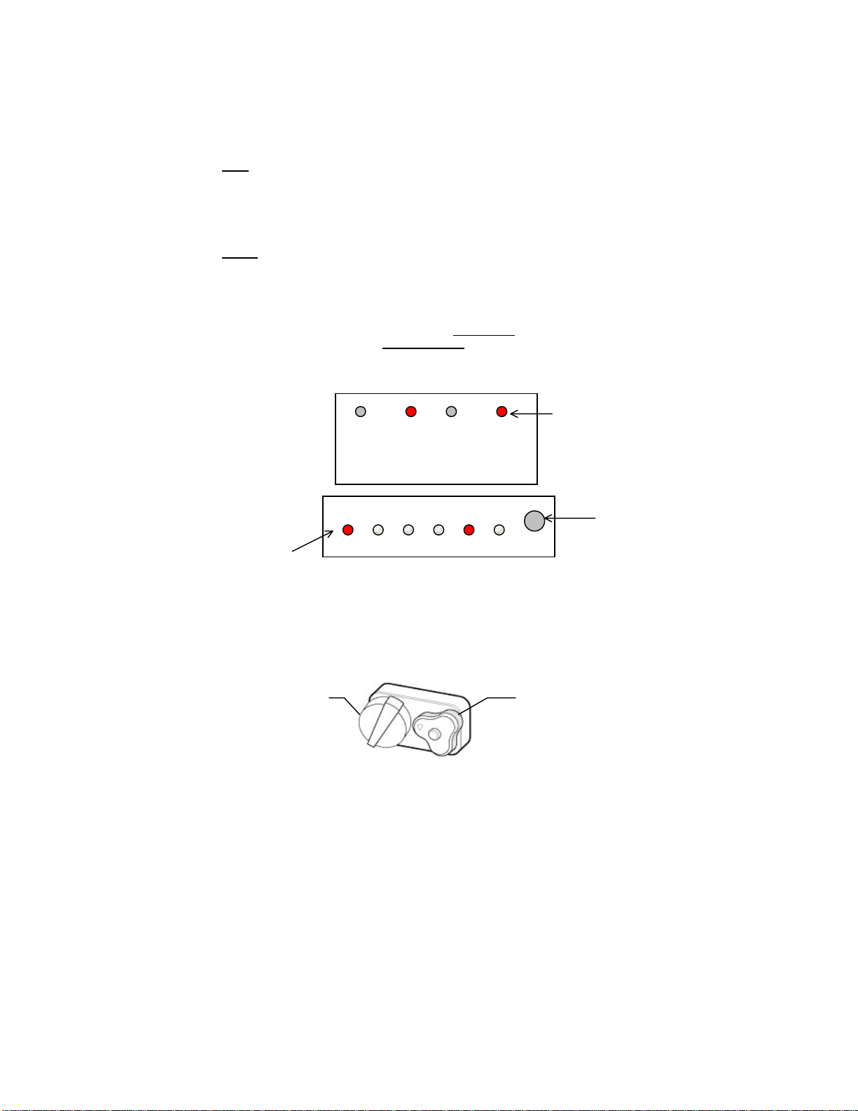
Welding Application “Heads Up” Display as seen by user
SMAC, MIG, TIG, 40 amps and above Delay 9, 10, 11, or 12
SMAC, MIG, TIG, 30 amps and above Delay TIG 9, 10, 11, or 12
Spot welding, 40 amps and above 9, 10, 11, or 12
Spot welding, 30 amps and above TIG 9, 10, 11, or 12
Note: The above settings are meant to illustrate which welding applications are
suggested for each configurable mode. Applications vary greatly so please
experiment with the many available setting combinations in order to find the best
combination of shade level, sensitivity and delay for your personal comfort and
performance efficiency.
Grinding Mode
Super Singles 240: press and hold grind/delay until LCD flickers to
indicate the change to grind mode. Press (DO NOT HOLD) and release
again to turn off (LCD will not flicker).
Xtreme X540F & X450F: press and hold sensitivity button until
“standard” LED flashes. Press (DO NOT HOLD) and release again to
turn off (LCD will not flicker).
Xtreme X540V & X450V: Press and hold grinding button until the LCD
flickers to indicate the change to grind mode. Press (DO NOT HOLD)
again to turn off (LCD will not flicker).
Industrial 540 & 450: Turn the sensitivity knob located on the outside of
the helmet clockwise to the lowest setting. This setting will work with
most grinding applications. If this setting is not low enough, press and
hold the delay/grind button until the LCD flickers. Press (DO NOT
HOLD) again to turn off (LCD will not flicker).
Industrial Xtreme: Turn the sensitivity knob located on the outside of
the helmet clockwise to the lowest setting. This setting will work with
most grinding applications. If this setting is not low enough, press and
hold the delay/grind button until the LCD flickers. Press (DO NOT
HOLD) again to turn off (LCD will not flicker).
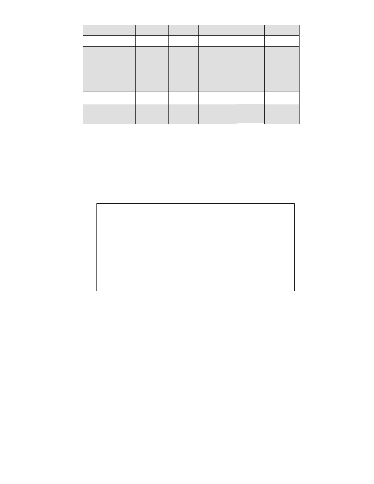
Recommended Welding Amperage Ranges (Table 2)
(The recommended range is based darkest shade available for the particular filter model)
Filter Model Shade Recommended
Range
Singles®240, 450, and 540 12 40 to 250
XT®450 and 540 10.5 40 to 200
Super Singles 240™, Xtreme™ 450F and 540F 10.5 30 to 210
Xtreme™ 450V and 540V 12 30 to 250
Shades™ 450 and 540 12 30 to 250
Industrial
™
240 13 35 to 250
Industrial
™
450 and 540 14 35 to 300
Industrial Xtreme™ 14 30 to 300
The recommended ranges stated above are to be used as a guideline. Lower
welding amperages may be achieved and are directly influenced by the
application. Upper range amperages can vary based on the comfort level that the
user requires. Caution: Do not exceed the filter temperature range (–14 to 148
degrees F)

- 6 -
Welding Helmets (Table 3)
Eagle®
(0200)
Hawk®
(0300)
Falcon™
(0400)
Vision®
(0500)
Hiderok
(
0600
)
Viper
(
0900
)
Material Nylon Nylon Fiberglass Nylon Thermal
Plastic Nylon
Applicable
Filters
S
Si
in
ng
gl
le
es
s®
®450
X
XT
T®
4
45
50
0
Shades™ 450
Industrial
™
450
Xtreme
™
450
S
Si
in
ng
gl
le
es
s®
®240
Super
Singles240™
Industrial
™
240
S
Si
in
ng
gl
le
es
s®
®5
54
40
0
X
XT
T®
5
54
40
0
S
Sh
ha
ad
de
es
s
™
5
54
40
0
I
In
nd
du
us
st
tr
ri
ia
al
l
™
5
54
40
0
S
Si
in
ng
gl
le
es
s®
®240
S
Si
in
ng
gl
le
es
s
™
™
540
Super Singles 240™
X
XT
T®
5
54
40
0
Shades ™ 540
Industrial
™
240
Industrial
™
540
Xtreme
™
540
S
Si
in
ng
gl
le
es
s®
®240 Xtreme
™
540
Industrial
™
540
I
In
nd
du
us
st
tr
ri
ia
al
l
X
Xt
tr
re
em
me
e™
™
Weight
(ounces) 16.25 14.75 17.25 17.6 13.75
Usage All applications
except
overhead
All applications
except overhead All applications All applications
except overhead
All
applications
except
overhead
All applications
except overhead
Maintenance
Your new filter requires virtually no maintenance other than periodic cleaning when the
lens becomes dirty or clouded from smoke. ARCONE®
Auto-Darkening Filters are water-
resistant and may be cleaned by using a soft cloth with a soapy water solution, or
standard window cleaner. By changing cover plates frequently you will extend the life of
your filter and guarantee the best operation possible. Additional front and rear cover
plates are available from your ARCONE®distributor (see Table 7 for part numbers).
NOTE: Using the wrong cover plates may damage your product and VOID
WARRANTY . Use genuine ArcOne replacement parts to ensure quality and fit.
Special note for X
XT
T®
users:
The extended viewing area is made of highly polished optical material. It has been hard
coated with a scratch resistant finish. IT IS NOT SCRATCH PROOF! The raised area,
around the perimeter of the case, suspends the cover plates above lens surface
therefore protecting the polished areas from abrasion. Clean your XT™as directed.
Please be careful to use a soft clean cloth or eyeglass wipes. Abrasive particles in a
dirty cloth could scratch the polished surface. Install ArcOne cover plates on both sides
of the filter to protect from spatter damage and further scratching.
NOTE: To keep your
X
X
T
T®
free from scratches Please take care of it as if it were
your personal eye glasses or the paint job on your favorite car or motorcycle.
Spatter Protection
SPATTER DAMAGE IS NOT COVERED BY WARRANTY
There are many reasons why spatter can damage the Auto-Darkening Filter. Missing,
incorrect, damaged, or distorted cover plates, and excessive spatter build-up in and
around the areas where the cover plates are retained are just a few examples. Any one or
combination of these will allow spatter to enter the filter area and pit the filter glass.

- 7 -
Spatter Protection (continued)
The Hawk®and Eagle®take a special 0.040” thick cover plate.
Using a nominal 0.060” cover plate will not work in this design.
The Hawk®and Eagle®Helmets are designed to accept polycarbonate cover plates
from the outside of the helmet without removing other components. This design
allows for quick and easy cleaning and cover plate replacement. The use on an
incorrect cover will distort the helmet and result in spatter entering the filter area.
Please use only ArcOne 0.040” inch cover plates in these products.
NOTE, change your cover plate when it loses its flexibility and or becomes bowed
or distorted. Clean any build-up from the area where the cover plate is retained.
All other helmet designs, other than the Hawk®and Eagle®, will accept either a
0.040” or a 0.060’ cover plate. Flip front designs must use 0.060” thick inner cover
plates for protection from particles produced when chipping or grinding.
The Hawk®and Eagle®have been designed to accept an additional protective lens.
This additional lens installs immediately in front of the auto-darkening filter and
behind the outer polycarbonate clear lens thus adding an even greater level of
spatter protection.
Users with excessive spatter applications can rely on the greater protection
provided by this options. See information below.
Part Numbers for Intermediate Cover Plates
Helmet Model Part No.
Eagle (0200) 02-OP
Hawk (0300) 03-OP
ANSI Shade Selection Guide (Table 4)
Operation Arc Current Minimum Shade Comfort Shade
Stick (SMAW) < 60 7 ---
60 to 160 8 10
160 to 250 10 12
250 to 550 11 14
MIG (GMAW) <60 7 ---
60 to 160 10 11
160 to 250 10 12
250 to 500 10 14
TIG (GTAW) <50 8 10
50 to 150 8 12
150 to 500 10 14
Carbon Arc-light <500 10 12
Carbon Arc-heavy 500 to 1000 11 14
Plasma Arc (PAW) < 20 6 8
20 to 100 8 10
100 to 400 10 12
400 to 800 11 14
Plasma Cutting < 300 8 9
300 to 400 9 12
400 to 800 10 14
Carbon Arc (CAW) --- --- 14

- 8 -
Single Shade Filter Specifications (Table 5)
S
Si
in
ng
gl
le
es
s®
®
240 S
Si
in
ng
gl
le
es
s®
®
450 & 540 S
Su
up
pe
er
r
S
Si
in
ng
gl
le
es
s
2
24
40
0™
™X
XT
T®
®
450 &
540 X
Xt
tr
re
em
me
e
™
™
450F & 540F
Viewing Area 1 3/8” by 3
¾”
5.25 sq. in.
1 3/8” by 3 ¾”
5.25 sq. in. 1 3/8” by 3 ¾”
5.25 sq. in. 12.5 sq. in.
Total Expanding
Viewing Area N/A N/A N/A Approximately
20 square
inches
NA
Grinding Mode N/A N/A Yes N/A Yes
Filter Dimensions 2” by 4 ¼”
0.2” thick 4 ½” by 5 ¼” or
5 ¼” by 4 ½”
0.2” thick
2” by 4 ¼”
0.2” thick 4 ½” by 5 ¼”
or
5 ¼” by 4 ½”
0.2” thick
4 ½” by 5 ¼”
or
5 ¼” by 4 ½”
0.246” thick
ARC Sensing 2 sensors 2 sensors 2 sensors 2 sensors 4 sensors
Sensitivity and delay N/A NA TIG and
Production N/A TIG and
Production
Switching Time
Seconds 5/10,000
(0.5
milliseconds
)
5/10,000
(0.5 milliseconds) 5/10,000
(0.5
milliseconds)
5/10,000
(0.5
milliseconds)
1/10,000
(0.1
milliseconds)
Primary Power Solar Cells Solar Cells Solar Cells Solar Cells Solar Cells
Back-up Power Lithium
Battery Lithium Battery Lithium Battery Lithium Battery Lithium Battery
Operating / Storage
Temperature -14 to 148
degrees F -14 to 148
degrees F
UV / IR Protection Up to
Shade 16 Up to
Shade 16 Up to
Shade 16 Up to
Shade 16 Up to
Shade 16
Dark to Light Delay 0.1 secs 0.1 sec 0. 1 and 2 secs. 0.1 secs 0.1 and 2 secs
Light Shade 2.5 32.5 32.5 2.5 2.5
Dark Shade 9, 10,
11 12 9, 10,
11 12 10.5 10.5 10.5
Certification ANSI Z87.1
- 1998 ANSI Z87.1 –
1998 ANSI Z87.1 –
1998 ANSI Z87.1 -
1998 ANSI Z87.1 -
1998
Variable Shade Filter Specifications (Table 6)
Xtreme ™
450V & 540V Shades™
450 / 540 Industrial™
240 Industrial™
450 / 540 Industrial Xtreme
™540V
Viewing Area 3 7/8” x 1 5/8”
12.5 sq. in. 3 7/8” x 1 5/8”
6.35 sq. in. 1 3/8” by 3 ¾”
5.25 sq. in. 3 7/8” x 1 7/8”
7.35 sq. in. 3 7/8” x 1 5/8”
12.5 sq. in.
Grinding Mode Yes N/A N/A Yes Yes
Filter
Dimensions 4 ½”x5¼” or 5¼” x
4 ½”
0.246” thick
4 ½”x5¼” or 5¼” x
4 ½”
0.270” thick
2” by 4 ¼”
0.25” thick 4 ½” x 5¼” or 5¼” x
4 ½”
0.25” thick
5¼” x 4 ½”
0.312” thick
ARC Sensing 4 sensors 2 sensors 2 sensors 2 sensors 4 sensors
Sensitivity and
Delay Standard or TIG Standard or TIG Fixed Standard or TIG Standard or TIG
Switching Time
Seconds 1/10,000
(0.1 milliseconds) 1/10,000
(0.1 milliseconds)
Primary Power Solar Cells Solar Cells Solar Cells Solar Cells Solar Cells
Back-up Power Lithium Battery Lithium Battery Lithium Battery Lithium Battery Lithium Battery
Operating &
Storage Temp -14 to 148
degrees F -14 to 148
degrees F
UV / IR Protection Up to Shade 16 Up to Shade 16 Up to Shade 16 Up to Shade 16 Up to Shade 16
Dark to Light
Delay 0.1 and 2 secs. 0.1 and 2 secs 0.1 secs 0.1 and 2 secs 0.1 and 2 secs
Light Shade 33334
Dark Shade 9 to 12 9 to 12 9 to 13 7 to 14 7 to 14
Certification ANSI Z87.1 - 1998 ANSI Z87.1 - 1998 ANSI Z87.1 - 1998 ANSI Z87.1 - 1998 ANSI Z87.1 - 1998

- 9 -
PART SELECTION GUIDE – MAJOR COMPONENTS (TABLE 7)
Part Numbers And Descriptions
AUTO-DARKENING FILTERS
Eagle®0200
4 X 5 fixed front
Hawk®0300
2 X 4 fixed front
Falcon®400
5 X 4 fixed front
Vision®0500
2 x 4 fixed front
Vision®L500
2 x 4 flip front
Vision®0500
5 x 4 fixed front
Viper 0900™
5 X 4 fixed front
Hiderok 0600
2 X 4 fixed front
Hiderok L600
2 X 4 flip front
Singles ® 240 (shade 9, 10, 11, or 12)
Singles ® 450 (shade9, 10, 11, or 12)
Singles ® 540 (shade9, 10, 11, or 12)
SuperSingles™
XT ™450
XT ™540
Xtreme™450 (X450F & X450V)
Xtreme ™540 (X540F & X540V)
Shades™450
Shades ™540
Industrial™240
Industrial™450
Industrial™540
IndustrialXtreme™
HELMETSSHELLS
2-0200 black, 0210 silver, 0220 red
3-0200 black, 0210 silver, 0220 red
2-0300 black, 0310 silver, 0320 red
3-0300 black, 0310 silver, 0320 red
2-0400black, 3-0400,4-0400
2-0500black, 0510silver, 3-0500black, 0510silver
324-0600 black only
324-L0600black only
2-0900black, 3-0900black
COVERPLATES
02-OP, Outside (4”x5”x0.040”)
03-OP, Outside (2”x4”0.040”)
SSIP, Inside (2”x4”0.040”)
SMIP, Inside (4”x5”x0.040”)
LF-IP, High impact for lift front models (2x4”x0.060”)
SHADE UPGRADES #1 & #2
SMIP-1 and SMIP-2
SSIP-1and SSIP-2
HEADGEARand COMPONENTS
01-HG, Completeheadgear assembly
03-HGSB Fatboy Sweat band
04-HGSB Headgear Sweat band
MISCELLANOUS CCOMPONENTS
SSML Magnifying Lens (1to2.5 power) (modified)
VML Magnifying Lens (1to2.5 power) (standard)
45ML Magnifying Lens with 4x5 adapter (1 to2.5 power)
54ML Magnifying Lens with 5x4 adapter (1 to2.5 power)
03-HH - Hard Hat with Adapter for Helmet
03-HGHH Hard Had Adapter
I-KAP,Shade Knob forIndustrialFilters W/O SETSCREW

- 10 -
Exploded Views (Figure 2-A)

- 11 -
Exploded Views (Figure 2- B)

- 12 -
Trouble Shooting Guide
It has become difficult to see through the filter:
•Clean or replace cover plates when they become dirty or discolored.
•Clean the auto-darkening filter by using a cloth with soapy water solution or standard
window cleaner
The Auto-Darkening Filter will not darken after striking an arc:
•Test the auto-darkening filter to a bright light source and simply run your finger
quickly over the sensor. The filter should darken momentarily then switch back to
the light state. Avoid blocking the solar panels. Once you are sure that the
equipment is functional you are now ready to begin welding.
•Make sure that the outer cover plate is clean, clear and unobstructed. Remove
and inspect the auto-darkening filter making sure that the sensors and solar
panels are unobstructed, clean, not broken, or discolored. Cease using this
product if problem persists. Contact ARCONE®Customer Service.
The Auto-Darkening Filter is slow to darken:
•ARCONE®solar powered auto-darkening filters are designed to operate on very low
voltage. If the filter has not been used for a period of time, such as a day or more,
the circuitry will enter a sleep state. In the sleep state the battery can retain full
voltage potential. It will awaken when you test it or begin welding. For instance if the
product is a shade 10, the first time it darkens it will initially darken to perhaps shade
8 then transition to shade 10. Then after that it will darken to shade 10 each and
every time. Note: As long as you are wearing your helmet with auto-darkening
filter you are protected from UV/IR (ultra-violet/infrared) rays in the dark and
light state and every shade in between.
•Colder temperatures will slow the switching speed of an auto-darkening filter. Once
the heat from welding process warms up the components, switching speeds will
increase. Auto-darkening filters work best at room temperatures.
The Auto-Darkening Filter goes light or flickers on/off while welding:
•Clean or replace outer clear polycarbonate lens if it becomes soiled or cloudy
•Check to make sure that the sensors and solar panels are not damaged, dirty, or
covered with a smoky film. Clean filter as directed. Your new filter requires
virtually no maintenance other than periodic cleaning if the lens becomes dirty or
clouded from the smoke. Both the Shades and new Industrial Auto-Darkening
Filters are water-resistant and may be cleaned by using a soft cloth with a soapy
water solution, or standard window cleaner. Make sure that the cloth you use is
clean. Abrasive particles in the cloth could scratch the highly polished lens
surface.
•Make sure that the sensors and solar panels are not being blocked. Your arms, the
welding torch or other objects can block the sensor or solar panels.
•The front of the auto-darkening filter should be perpendicular to the welding arc.
application: MIG or TIG
•Observation/Complaint: Flickers on and off sometimes while MIG and TIG welding
•Possible cause of malfunction:Both MIG and TIG applications utilize “GUN” or
“Torch” that has a nozzle with the electrode protruding only slight from it. Depending
on the technique of the welder and the way that he positions the “Gun” or “Torch” the
nozzle can block the welding arc from the sensors. Even though the welder can see
the arc perfectly the sensors may only be able to see the nozzle and not the arc.
NO ARC – THE LENS WON’T WORK!
Possible Solution:Please rotate the filter 180 degrees so that the sensors and
solar panel are located at the bottom. In this configuration the sensors will have a
completely different view of the application. Hopefully one that is unobstructed. If
the Filter does not hold the dark shade contact ARCONE®Customer Service.

- 13 -
Trouble Shooting Guide (continued)
The Auto-Darkening Filter stays dark after you stop welding:
Exceeding the temperature limitations may also cause the LCD to stay dark. Let the
filter cool down and try not to over heat it again by viewing the arc from the side and
not directly above or by increasing the distance the filter is in relationship to the arc.
Your filter may remain dark after welding if you are facing a bright light or the sun. If
this is the case either look away or pass your hand between the source of light and
the sensors. By doing this the light source will be interrupted and the filter will clear.
The Auto-Darkening Filter has a crack running through the front viewing area:
•UVIR protection may be compromised resulting in burns caused by Ultraviolet or
Infrared radiation. Cease using this product if the problem exists. Contact
ARCONE®Customer Service.
The Auto-Darkening Filter appears dark in the center and lighter around the
edges:
•You are most likely experiencing a common characteristic of an LCD known as
angle dependency. See Technical Information on Angle Dependency (page 2)
Spatter is causing damage to the filter:
•There are many reasons why spatter can damage the Auto-Darkening Filter.
Missing incorrect damaged, or distorted cover plates, and excessive spatter build-up
in and around the area where the cover plates are retained are just a few examples.
Any one or a combination of these will allow spatter to enter the filter area and pit the
filter glass.
The Auto-darkening Filter has severe spatter damage :
•Do not operate this product if this condition exists. The UV/IR protection may be
compromised. Unfiltered welding light may penetrate through the filter and may
result in severe eye damage and burns
* Note: When using Mig and Tig applications, Mig and Tig utilize "Gun" or "Torch"
that has a nozzle with the electrode protruding out slightly from it. Depending on
the technique of the welder and the way that he positions the Gun or Torch the
nozzle can block the welding arc from the sensors. Even though the welder can see
the arc perfectly the sensors may only be able to see the nozzle and not the arc.
Please rotate the filter 180 degrees so that the sensors and solar panel are located
at the bottom. In this configuration the sensor will have a completely different view
of the application.
F
Fi
il
lt
te
er
rR
Re
em
mo
ov
va
al
l
D
Di
ia
ag
gr
ra
am
m(
(F
Fi
ig
gu
ur
re
e
4
4)
)

- 14 -
Warranty and Service Information
LIMITED WARRANTY
ARCONE®warrants all auto-darkening filters for two (2) years from the date of purchase
against manufacturing defects resulting from materials or workmanship. Proof of purchase
establishing the date of sale and filter serial number must be provided, should a warranty
claim be submitted. The purchaser’s only remedy under this limited warranty shall be
limited to ARCONE’s sole option to repair, replace or refund (not to exceed the purchase
price). This limited warranty is void in the case of unauthorized modification, tampering,
and damage due to misuse, abuse, inadequate maintenance or improper storage. This
limited warranty is not transferable from the original purchaser to a secondary owner.
ARCONE®shall in no event be liable or responsible for any injury, damage or loss resulting
either directly or indirectly from the use or misuse of this product. This limited warranty is
exclusive and is in lieu of any other warranty implied either oral or written. Please read the
instruction manual carefully to avoid certain situations which may void this limited
warranty.
In the unlikely event that the auto-darkening filter malfunctions, the following procedures
are to be used to receive efficient service and repair:
Determine if the product is damaged from abuse or misuse. Any pitted
marks on the filter possibly from spatter, chips or dents, or cracks, etc., are
some indications of operator abuse. In the case of operator abuse, the
warranty is void.
If you need to return your filter follow the Return Procedure below.
RETURN PROCEDURE
Please Do not contact the distributor or retailer
from whom you purchased the filter
1. Remove the auto-darkening filter from the helmet (see figure 3). Record the model
number and serial number which are located on the top edge above the solar panel,
and also record the date of purchase from your sales receipt.
2. Contact ARCONE®Customer Service (800-223-4685) for a Return Tag Number.
Please return only the auto-darkening filter unless the customer service
representative requests otherwise. Pack the filter in a box with adequate packing so
no additional damage can occur. Send only the auto-darkening filter, freight prepaid,
directly to the ARCONE®Division, A.C.E. International, 85 Independence Drive,
Taunton, MA. 02780.
3. Reference your assigned Repair Tag Number on the outside of the package and on
all accompanying paperwork.
4. Provide your complete return address and telephone numbers.
5. Provide an accurate description of the problem along with welding application details
such as MIG, TIG, etc., and amperage range.
6. Should there be any charges for non-warranty repairs, Visa, MasterCard, or checks
are the only forms of payment accepted. In the case of credit cards purchases
include credit card number expiration date, the full name as it appears on the card,
and your signature as authorization for the total repair amount.
7. AII returns, which follow the above procedures, will be processed within 2 business
days.
8. All warranty repairs are covered for the balance of the original warranty period,
which is established from your proof of purchase date.
9. AII non-warranty repairs carry a 90-day, limited warranty. The period begins the
date the product is returned to you.
Note:, SuperSingles & Xtreme are trademarks of A.C.E. International. ArcOne, Shades, Industrial, Single, XT,
Eagle, Hawk, Falcon & Vision are registered trademark of A.C.E. International

- 15 -
A
Ar
rc
cO
On
ne
e
A
Al
ls
so
o
O
Of
ff
fe
er
rs
s
A
A
C
Co
om
mp
pl
le
et
te
e
L
Li
in
ne
e
O
Of
f
R
Re
es
sp
pi
ir
ra
at
to
or
ry
y
S
Sy
ys
st
te
em
ms
s
a
an
nd
d
W
We
el
ld
di
in
ng
g
M
Ma
ac
ch
hi
in
ne
es
s
PAPR & SAR Respiratory Systems
ArcOne’s Powered Air Purifying and
Supplied Air Respiratory Systems offer a
high level of protection from particulates,
fumes & vapors. One unit with a variety of
interchangeable head tops, multiple
welding helmets and auto-darkening
filters to choose from. Depending on your
work environment, ArcOne has the
respiratory system to meet your welding
or industrial needs.
ArcOne’s 100 amp.,115 volt model and
powerful 200 amp., 230 volt work
horse are lightweight, and energy
efficient. Made for DC TIG and stick
applications they both come with hot
start, anti-stick, lift arc and socket
for remote amperage control. They will
more than satisfy the most demanding
welders. ArcOne also offers many
accessories and options to make your
j
ob easier such as TIG torches, a variety
of ground clamps and electrode holders
to meet your amperage and cable length
requirements.
ARCONE®is a Division of A. C. E. International Company
85 Independence Drive,
Taunton, MA 02780
Tel: 508-884-9600 Toll Free: 800-223-4685 Fax: 508-884-9666
Web Site: www.arc1weldsafe.com
This manual suits for next models
14
Table of contents
Other ArcOne Welding Accessories manuals
Popular Welding Accessories manuals by other brands

Solter
Solter OPTIMATIC instruction manual

Abicor Binzel
Abicor Binzel AUT 61GD operating instructions

Miller Electric
Miller Electric Roughneck C-Series Specifications

Abicor Binzel
Abicor Binzel CAT3 operating instructions

Lincoln Electric
Lincoln Electric DH-10 Operator's manual

Miller
Miller PipeWorx 350 owner's manual

A.C.E. International Company
A.C.E. International Company ArcOne Singles Series manual

Miller
Miller SUITCASE 12RC Technical manual

EWM
EWM Tetrix drive 4L operating instructions

Lincoln Electric
Lincoln Electric X-Tractor 3A Operator's manual

Sundstrom
Sundstrom SR 584 Instructions for use

Swagelok
Swagelok 5 Series user manual