Arctiko Integraline ULUF P390GG User manual

Integraline RANGE
ULUF P390GG / P500GG / P610GG / P820GG
OPERATING
INSTRUCTIONS

32
TABLE OF CONTENTS
INTRODUCTION 4
Symbols 4
Abbreviations 4
SAFETY 5
Intended use 5
Personal safety 5
HANDLING & TRANSPORTATION 6
Moving the unit 6
Packaging 6
Unpacking 6
Inactivity for extended period 6
Disposal 6
INSTALLATION 7
Preparing the unit 7
Refrigerant 7
Location 7
Electrical connection 8
Getting started 9
PRODUCT DESCRIPTION 10
Cabinet overview 10
Cabinet details 11
Cabinet description 12
Probes and portholes 13
Dual cooling technology 13
Filterless construction 13
Remote alarm contact 13
Vacuum valve 14
Display 15
Keyboard 15
Action icons 16
Info events 16
Door warning 16
Temperature alarms 17
Failure events 17
Compressor failure alarm 18
Outcome frames 18
Warnings 19
How to turn on device 20
How to turn o device 20
Menu user 21
How to change the setpoint 22
How to change alarm limits 22
Access log 23
Ecomode settings 23
Event list 24
Graphs 24
Menu settings 26
How to set date/hour 27
How to change language 27
Password settings 27
Alarm test 28
Machine name 28
Default settings 29
Data download 29
Open and process data on a computer 30
Rating plate 31
Description of data points 31
MAINTENANCE 32
General maintenance 32
Cleaning 32
Defrosting 33
Service 33
Spare parts 33
AFTER SALES 33
WARRANTY 33
TROUBLE SHOOTING 34

4 5
OPERATING INSTRUCTIONSOPERATING INSTRUCTIONS
INTRODUCTION SAFETY
Arctiko is obligated as a supplier to ensure the
users safety when operating one of our units. To
prevent personal and material injury or damage,
please follow the instructions in this manual.
INTENDED USE
Ultra-low temperature units are designed for
storage of biomedical products at a constant
temperature in clinical, pharmaceutical, research
and laboratory fields, and can also be used for
commercial use. The units are designed to operate
within a temperature range of -40°C to -86°C at a
maximum ambient temperature of 32°C. For safe
and optimal performance of the unit, it should only
be placed indoors, in a well ventilated room and in
elevations below 2000m. The unit should only be
operated by instructed personnel.
PERSONAL SAFETY
When operating an ultra-low temperature freezer,
you are exposed to a variation of possible
dangerous events.
• Read and understand this manual. If in doubt,
contact your local Arctiko distributor.
• Use freezer gloves at all times when loading or
unloading the unit. The temperature of operation
is such that direct contact with the cold contents
or inside the unit can burn unprotected skin.
• Assure good cleaning practices at all times by
keeping the unit and the adjacent areas clean,
dry and uncluttered.
• Do not store explosive substances such as
aerosol cans with a flammable propellant inside
the unit.
Prohibition
Do not insert metal objects such as pins or
wires into any vent, gap ors outlet on the
unit. This may cause electric shock or injury by
accidental contact with moving parts.
WARNING
Do not use mechanical devices or other
means to accelerate the defrosting process,
other than those recommended by the
manufacturer.
WARNING
Do not damage the refrigerant circuit.
WARNING
Do not use electrical appliances inside the
food storage compartments of the unit,
unless they are of the type recommended by
the manufacturer.
Follow procedures
When removing the power plug from the
outlet, pull on the plug, not the cord. Pulling
the power cord may result in electric shock
or fire by short circuit.
WARNING Flammable material
This unit contains flammable refrigerants.
Please take a few minutes to read and become
familiar with the advantages of your unit. To meet
the high quality demands required by the medical
and pharmaceutical industry, at least 10% of all
units that leaves Arctiko are carefully checked and
tested to ensure high performance and quality. If
the operating and installation instructions describe
dierent models, any dierences will be pointed
out at the relevant points in the text. Read these
operating and installation instructions before
switching on the unit.
If you would like to obtain further information about
this unit, please visit our website www.arctiko.com
where downloads are available on the page of each
specific product.
SYMBOLS
WARNING
Performing this action can cause injury.
CAUTION
Risk of personal or material injury. Consult
the instructions before attempting to use this
equipment.
Prohibition
Action is strictly prohibited.
Follow procedures
Keep the instructions handy for convenient
reference.
OFF
Disconnect from power outlet before operation.
WARNING Flammable material
This unit contains flammable refrigerants.
Grounding
Be aware that the unit is grounded.
Fragile
Handle with with care. Indicates a device that
can be damaged or broken if not handled with
care.
ABBREVIATIONS
SYMBOL DESCRIPTION
AAmps
WWatts
VVoltage
°C Degrees Celcius
HHour
Min Minutes
MM Millimeters
Kg Kilograms
N/A Not applicable
ULT Ultra-low temperature
INTRODUCTION SAFETY

6 7
OPERATING INSTRUCTIONSOPERATING INSTRUCTIONS
HANDLING & TRANSPORTATION
MOVING THE UNIT
Lifting, moving and transporting the unit without
suitable equipment may cause personal injury
or material damage. Always use suitable lifting
equipment to load, unload and move the unit.
OFF
Disconnect from the power outlet before
moving the unit. Make sure not to damage
the power cord. A damaged power cord
may cause electric shock or fire.
Follow procedures
Be careful not to damage the unit during
transport.
PACKAGING
• Do not expose the package to rain.
• Always keep the package upright. DO NOT
BRING THE PACKAGE TO A HORIZONTAL
POSITION.
• Do not expose the package to bumps and
shocks.
• Package contents are fragile.
UNPACKING
1. Inspect the packaging carefully for any damage
that may have occurred during shipping. If
damage is observed, report to the shipping
company and your local Arctiko distributor.
2. Remove all packaging material, plastic and
straps. All packing materials are entirely
recyclable. For more information on where to
dispose of waste, contact your local authority or
recycling station.
Prohibition
Plastic bags pose a suocation risk.
Keep away from children.
INACTIVITY FOR EXTENDED PERIOD
If the unit must be switched o for a longer period
and stored away, take the following precautions:
• Clean the unit both inside and outside.
• Ventilate the unit and make sure it is completely
dry.
• Disconnect from the power outlet.
• Leave the door slightly open in order to prevent
rot and mold.
OFF
Disconnect the unit from the power outlet
when it is not in use for a longer period.
Keeping the unit plugged in may cause electric
shock, current leakage or fire due to the
deterioration of insulation.
Follow procedures
If the unit is to be stored unused in an
unsupervised area for an extended period,
ensure that children do not have access and
that doors cannot be closed completely.
DISPOSAL
In the event of disposal of the unit, observe relevant
legal regulations to prevent harmful environmental
eects.
Within the European community, EU directives
regulate disposal of electrical devices.
This unit is marked in compliance with the 2002/96/
CE European Directive, WASTE ELECTRICAL AND
ELECTRONIC EQUIPMENT (WEEE).
OFF
Disconnect power supply before operation.
CAUTION
Risk of personal or material injury during
disposal of components.
WARNING Flammable material
This unit contains flammable refrigerants.
INSTALLATION
PREPARING THE UNIT
• Unpack the unit: Remove all packaging materials,
plastic bags and straps.
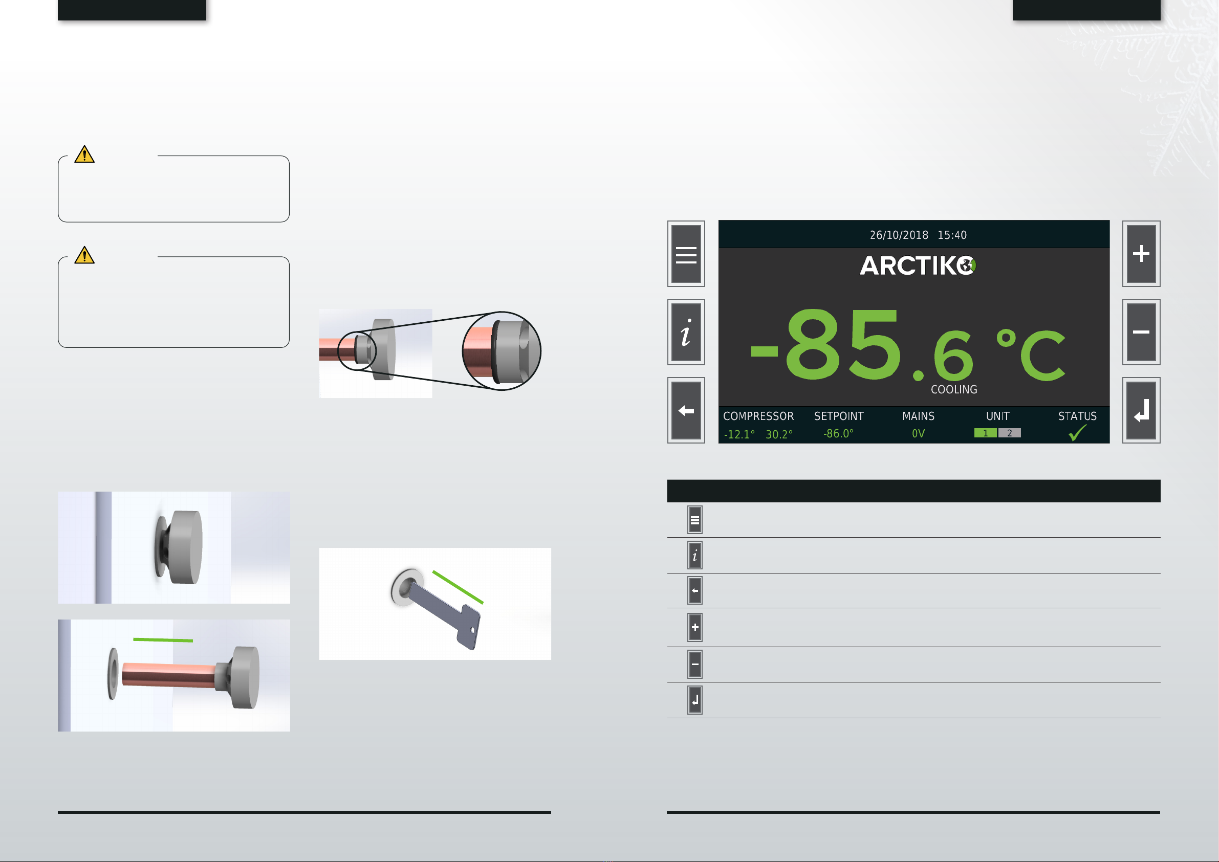
• Storing the key: The key for the door lock is
strapped to the backside of the unit. Remove
the key from the cable carefully without causing
damage to the cable. Keep the key in a safe place.
• Read the Quick Start Guide: The Quick Start
Guide is provided with the unit.
• Ventilate the unit: Open the door for at least
20 min, in order to ventilate the unit before
first use. The unit may contain odors from
manufacturing.
• Clean the unit: Clean the unit on the inside and
outside with a soft cloth/sponge using a solution
of water and light detergent. After cleaning all
surfaces of the unit, wipe the inside with a dry
rag.
• Remote alarm contact: The terminals for the
remote alarm contact are located on the backside
of the unit (see Cabinet description). The contact
design is a maximum load of 2A. The remote
alarm contacts work in synchronization with
the buzzer alarm on the unit. When an alarm is
accepted on the display the remote alarm relay
will return to normal. The remote alarm can be set
as normally open (NO) or normally closed (NC).
REFRIGERANT
Please see the serial plate axed to the unit, to
obtain information about the refrigerant.
LOCATION
Place the unit in a location that complies with the
following conditions in order to achieve optimal
operating results:
• Firm and levelled floor: Installing the unit on a
firm and flat floor reduces the risk of excessive
noise and vibration.
• Away from any heat sources: Avoid placing the
unit near any heat dissipating devices such as a
gas burner/stove, radiator, oven or other source
of heat. Exposing the unit to heat will lower the
performance.
• Place the unit away from direct sunlight: Placing
the unit in direct sunlight may cause reduced
performance and shorten the life expectancy.
• Dry area:Avoid placing the unit near damp areas
such as water faucets and sinks.
• Clean area: Placing the unit in a clean
environment will reduce risk of function failure.
Avoid installing the unit in or near chemicals and
materials that might have outgassing property to
avoid corrosion.
• Well ventilated: There must be sucient space
around the unit to ensure air ventilation. Lack of
such space will reduce the cooling capability of
the unit. Place the unit with at least 10 cm free
space to each side and 15 cm behind the unit.
• Do not place any objects on top of the unit.
Min. room size (A) for installation:
UNIT CHARGE PER CIRCUIT G A (m2)
P390 GG 149 None
P500 GG 190 4.55
P610 GG 219 5.24
P820 GG 270 6.46
WARNING
An electrical power plug with a ground
connection must be used to power the unit.
This is to prevent electrical shock.
Prohibition
Do not use the unit outdoors. Current
leakage or electric shock may result if the
unit is exposed to rain.
HANDLING & TRANSPORTATION INSTALLATION

8 9
OPERATING INSTRUCTIONSOPERATING INSTRUCTIONS
Prohibition
Never install the unit in a flammable or
volatile location. This may cause explosion
or fire.
Follow procedures
Install the unit on a sturdy floor and take an
adequate precaution to prevent the unit from
tipping.
ELECTRICAL CONNECTION
In order to ensure an economical and reliable
installation that complies with the limits of
temperature and voltage drop, it is necessary to
determine maximum load of units connected to the
installation. In determining the maximum load for
an installation or for a part of it, it is vital to take into
account contemporaneous factors.
For supply systems, the following must be
determined:
• Power system (AC/DC): Data regarding voltage
and absorbed power/current is given on the
rating plate.
• Ground protection: To prevent the user of getting
exposed to electrical shock, in the event of a
insulation damage, the unit must be grounded.
• The installation must always be secured with a
minimum 10A fuse.
• If you have more than one unit, each unit must be
connected to an individual fuse group.
When installing the unit, make sure the protected
earth is grounded. If the connection is a 3-pole
connection, use a three-pin plug and connect the
conductor with yellow/green insulation to ground.
In order to maintain a stable operation of the unit,
voltage variation cannot dier more than ±10% of
the nominal voltage supply.
Always follow local regulations when preparing an
installation. Contact your local authorities if in any
doubt.
Maximum current rating (Ambient 20°C):
UNIT AMPS A
P390 GG 10
P500 GG 10
P610 GG 10
P820 GG 12
Maximum current rating (Ambient 32°C):
UNIT AMPS A
P390 GG 11
P500 GG 12
P610 GG 12
P820 GG 12
Follow procedures
Only qualified/authorized engineers or
service personnel should install the unit.
Installation by unqualified personnel may
cause electric shock or fire.
Grounding
Always make sure the unit is grounded to
protect the user from electrical shock.
Prohibition
Do not use the power cord if it is damagaged.
Such supply cord may cause fire or electric
shock.
Prohibition
Never use a telephone line or lightning rod as
ground protection. During lightning, there is a
strong current present, which is extremely
dangerous.
Prohibition
Do not use water pipes as ground protection.
Modern water pipe systems are non-
conductors such as PVC.
Follow procedures
Replacing the power cord may only be done
by authorized personnel.
OFF
Disconnect the power cord if there is
something wrong with the unit. Continued
abnormal operation may cause electric shock
or fire.
GETTING STARTED
During the initial startup and continuous usage of
the unit, the following procedures shall be followed:
1. Plug the power socket in a dedicated outlet.
For correct voltage requirement, follow the
information on the rating plate. When started,
let the unit cool for 24 hours before placing any
products in it.
2. When the unit initially starts up, the buzzer
alarm may sound. This is normal. You can
accept the alarm on the display.
3. This unit has been set to operate at -80°C from
the factory.
4. Check the functionality of the light by opening
the door.
5. Once a thorough inspection of the unit is
completed, products can be loaded into the
unit. Products should be pre-frozen when
inserted into the unit, otherwise this can aect
the cooling performance of the unit.
Prohibition
Never use gas lines as the ground protection
for the unit. This can cause an explosion.
INSTALLATION INSTALLATION

10 11
OPERATING INSTRUCTIONSOPERATING INSTRUCTIONS
1
2
3
7
4
6
5
9
8
12
18
17
16
15
11
10
11
5
11
13
14
2
4
8
9
10
11
12
13
14
16
19
PRODUCT DESCRIPTION
The Integraline range oers the best ultra-low
temperature freezing with high performance and
stability. Standard features are noise reduction
technology, dual cooling system, VIP panels, air flow
control, filter-less construction for less maintenance,
low noise level, low energy consumption, low heat
dissipation and excellent temperature stability.
The compressors and cooling system is located in
the top of the unit for easy maintenance and access,
ergonomically correct work position and less
generation of heat in your working area.
CABINET OVERVIEW
CABINET DETAILS
PRODUCT DESCRIPTION PRODUCT DESCRIPTION

12 13
OPERATING INSTRUCTIONSOPERATING INSTRUCTIONS
NO. AREA DESCRIPTION
1Top panel Compressor compartment lid, fitted with control panel.
2Display See display.
3LED light Secure work light.
4Door switch Monitors the door openings and control the lights.
5Probe See Probes and portholes.
6Door handle with lock For easy opening, closing and locking the door.
7Heated door frame Prevents ice build up on door.
8Inner doors Removable inner doors.
9Vacuum valve Equalizes the pressure in the unit.
10 Adjustable shelves Shelves that are easy to adjust.
11 Fixed shelf This shelf cannot be adjustet.
12 Castors 2 pcs. in front with brake, 2 pc. back without brake.
13 Portholes See Probes and portholes.
14 Evaporators Provides a constant temperature in each compartment.
15 Cover for noice reduction and air
flow management -
16 Remote alarm connection For connecton of additional alarm equipment.
17 Top panel latch For opening and closing the top panel.
18 Compressor compartment The compressor compartment is located in the top of the unit.
19 Racks and boxes Optional equipment (racks and boxes).
PROBE AND ACCESS PORTS
As standard, the unit is equipped with a
temperature probe inside the chamber. The probe
monitors the temperature in the chamber and
controls the operation of the compressors.
The main probe also controls temperature alarms.
It is possible to connect two dierent probes to the
unit in order to monitor the temperature dierent
places in the unit. You can change the settings on
which probe is the main probe.
To install more probes, you can use the premade
access port(s) on the back of the unit. Carefully
push a screwdriver or similar through the holes.
Always seal the holes with putty on both sides of
the hole.
Follow procedures
Never install probes through the door as this
will deteriorate the functionality of the door
gasket, increase the ice build-up and aect
the temperature inside the unit.
DUAL COOLING TECHNOLOGY
Our Integraline models ULUF P390GG / P500GG /
P610GG / P820GG comes with dual cooling system.
The dual cooling system oers two independent
cooling cycles and thereby optimal security of
your stored products in the unlikely event of failure
in one of the cooling cycles. In case of failure,
the other cooling cycle will serve as a backup,
guaranteeing that your stored products will be kept
at a safe temperature.
FILTERLESS CONSTRUCTION
Arctiko’s dual compressor system is designed as
a filter-less system, which prevents malfunctions
caused by dust build-up in the filter. This minimizes
the maintenance of the cooling system and secures
a more stable operation.
REMOTE ALARM CONTACT
The remote alarm contact is located on the
backside of the unit.
NC NO
CABINET DESCRIPTION
PRODUCT DESCRIPTION PRODUCT DESCRIPTION

14 15
OPERATING INSTRUCTIONSOPERATING INSTRUCTIONS
DISPLAY
Easy and user-friendly control panel, with a 6-key
resistive keyboard. You can access a variation of
settings, in order to adjust your unit for your exact
needs. A 4GB microSD is provided as standard,
installed internally for recording functional data
every 30 seconds with a memory capacity of about
10 years.
In the single temperature configuration two types
of Home Page are provided: EASY or SCIENTIFIC.
The external ESCAPE key selects one mode or the
other. The header shows the MACHINE_NAME (in
the example LABORATORY) that can be edited from
the SETTINGS MENU.
SYMBOL KEY DESCRIPTION
MENU KEY Accesses the menu panel.
INFO KEY Accesses the info pages from Home Page level.
ESCAPE KEY Goes to previous level.
Switch between easy/scientfic Home Page.
UP KEY Increase value of selected parameter.
Select multi-page menu.
DOWN KEY Decrease value of selected parameter.
Select multi-page menu.
ENTER KEY Store the selected value.
VACUUM VALVE
The vacuum valve helps equalize the pressure
inside the unit, which allows the user to open the
door without waiting for hours.
WARNING
The vacuum valve requires regular attention
and cleaning to be fully operational. Misuse
could cause the unit to be inaccessible for up
to three hours.
WARNING
Regular cleaning and ice removal is necessary
to maintain full function of the vacuum valve.
The cleaning frequency depends on dierent
conditions such as the number of door
openings, ambient temperature and humidity
at the installation site.
Recommended cleaning procedures
It is important to clean the valve regularly. It is
recommended to clean the valve every second
week or in case of ice build-up.
1. To clean the valve, pull it out from the exterior
side of the door as shown on the illustration
below (no tools are required):
2. Rinse the valve on the exterior side with cold tap
water for 2 to 5 minutes or until all ice inside the
valve is removed. Make sure the vacuum valve
is completely dry before inserting it into the tube
and be aware that it is inserted correctly (push it
firmly until it clicks in).
It is recommended to remove ice build-up
around the vacuum valve on the interior side
of the unit regularly as well as ice removal from
the inner doors and gaskets is recommended
to maintain the performance of the unit and the
vacuum valve.
3. Before inserting the vacuum valve into the tube
in the door, assess the O-ring for any damage or
misplacement. Make sure to pull the O-ring all
the way to the end, like in the illustration below:
The vacuum valve is removed but the
door cannot open
If the door cannot open after removing the vacuum
valve from the tube in the door, the tube may be
blocked by ice. Carefully use the enclosed key to
remove the ice (do not use sharp objects) and clear
the passage.
See “Recommended cleaning procedures” to learn
how to maintain the vacuum valve. This will reduce
the risk of ice build-up in the tube in the door.
►
►
PRODUCT DESCRIPTIONPRODUCT DESCRIPTIONPRODUCT DESCRIPTION

16 17
OPERATING INSTRUCTIONSOPERATING INSTRUCTIONS
ACTION ICONS
ICON ACTION
no
icon PAUSE
WAITING COOLING
COOLING
DEFROST
DRIPPING
HEATING
WARM
DRY
CO2 BACKUP
STOP ACTIONS
INFO EVENTS
ICON EVENTS
ALARM ON
FAILURE STATUS
NOTIFY
DOOR WARNING
-16°
DOOR ALARM
-18°
DOOR OPENED
TEMPERATURE ALARMS
LOW/HIGH TEMPERATURE PREALARM
ALARM OCCURRED
HIGH TEMPERATURE ALARM
LOW TEMPERATURE ALARM
FAILURE EVENTS
FAIL OCCURRED
1. To accept a failure, press the center of the screen.
2. Jump to EVENT LIST to check the failure.
3. In case of a unresolved failure, the icon FAIL
UNRESOLVED will be shown on the screen.
4. If any alarm has occurred, the icon NOTIFICATION
OF PREVIOUS ALARM will appear on the screen.
PRODUCT DESCRIPTIONPRODUCT DESCRIPTION

18 19
OPERATING INSTRUCTIONSOPERATING INSTRUCTIONS
COMPRESSOR FAILURE ALARM
The controller is equipped with a compressor failure
detection feature. If the controller detect an unusual
temperature profile on one of the compressors it
will disable that compressor and activate an alert
on the controller. The other compressor will keep
running.
To reset the alarm and reenable the compressor;
accept the alarm and turn the unit o and on again.
During pulldown this alarm may be activated. If this
happens please reset the alarm. If the alarm keeps
reoccuring please contact your distributor or Arctiko
service for help.
COMPRESSOR FAILURE ALARM OCCURED
1. To accept a failure, press the center of the screen.
2. Jump to EVENT LIST to check the failure.
COMPRESSOR FAULT
HIGH TEMP. AFTER BLACKOUT
LOGIC FAILURE
COMPRESSOR FAULT
k1
1 <-> 2
19.8 c
0 m
k1
3. If any alarm has occurred, the icon
COMPRESSOR FAILURE ALARM OCCURRED
will appear on the screen.
12
19.8
cooling
OUTCOME FRAMES
The outcome frames will be accompanied by a
long beep.
ERROR
INVALID VALUE
CONFIRMED
ESC/CONFIRM
WARNINGS
To accept a warning press ENTER.
PRODUCT DESCRIPTION PRODUCT DESCRIPTION

20 21
OPERATING INSTRUCTIONSOPERATING INSTRUCTIONS
HOW TO TURN ON THE DEVICE
1. Press on the screen and hold, to turn on the
device.
2. If password protection is enabled, type password
and press ENTER.
3. The main screen should appear.
HOW TO TURN OFF THE DEVICE
1. Press MENU to access the USER MENU.
2. Press and hold STANDBY to turn o the device
(put in standby mode).
3. If password protection is enabled type pasword
and press ENTER.
4. The standby mode should appear.
MENU USER
ICONS DESCRIPTION
STANDBY Press and hold to turn o the controller.
SETPOINT Change the temperature setpoint.
LIMITS Set the high/low temperature limits and alarm delay.
ACCESS LIST Access log.
ECOMODE Set the ECOMODE parameters.
EVENTS Displays the alarms and failures recorded.
GRAPH Displays the daily temperature graph from calendar.
DEFROST Start the defrost and displays temperature and time phase
(defrost function not available on Integra range).
SETTINGS Access to MENU SETTINGS.
SERVICE Access to MENU SERVICE.
PRODUCT DESCRIPTIONPRODUCT DESCRIPTION

22 23
OPERATING INSTRUCTIONSOPERATING INSTRUCTIONS
How to change the setpoint
1. Press SETPOINT to enter the setpoint
adjustement.
2. Press the UP to increase the temperature or the
DOWN to decrease the temperature. Once the
temperature has been set press ENTER to save
the new value and exit.
3. Incase you wish to recall values, press one of the
following keys on the screen:
KEY FUNCTION
STANDARD Recall standard value
MIN Recall minimum value
MAX Recall maximum value
ACTUAL Recall running value
4. Press confirm to accept the new values.
How to change the alarm limits
1. Press MENU to access the user menu.
2. Press LIMITS in the user menu.
3. Key functions.
• UP/DW increases/decreases the value selected
with the SELECT key.
• STANDARD sets the default value.
• ABSOLUTE sets in rotation the type of limit
setting; the high and low temp. limits in the control
board are always absolute. The calculated value
of the limits is displayed under the panel title.
• SELECT enables in rotation the value to be set.
• ACTUAL retrieves the value in progress/preset.
• ESCAPE returns to the user menu without saving
the map of values with confirm request.
• ENTER returns to the user menu saving the map
of values with confirm request.
Access log
1. Press ACCESS LOG from user menu to access the
display of the list of the last 32 events accesses.
2. If you wish to consult previous logons make a
BACK-UP data and open the contents of USB
through the application THERMO CONVERTER
where in the last 4 fields to the right are the
records accesses with the description by means
of the actions carried icons.
Description of the icons used in the access log:
POWER OFF
CHANGED SETPOINT
CHANGED PARAMETER
FORMATTED CARD
DOOR OPENED
CHANGED HIGH LIMIT TEMPERATURE
BURGLARY
POWER-ON
Ecomode setting
Press ECOMODE icon to displays the setting panel
of the hourly or automatic temperature profile.
With USER password dierent from zero, it is
requested to access the setting of the new
configuration. The password is edited via the
numerical keypad and confirmed by pressing
ENTER. If the password was correctly set the
ECOMODE frame is accessed, otherwise the ERROR
frame appears and the display goes back to the
USER MENU.
Press UP/DW to increase/decrease the value
selected. The map of values is saved by pressing
the external ENTER key with request to confirm.
ECOMODE OFF
Press ON/OFF to disables/enables ECOMODE; if
the key is at OFF the other keys are disabled.
ECOMODE AUTO
Press AUTO/TIMER to set in rotation the ECOMODE
TIMER/AUTO function; in TIMER mode the SELECT
key is disabled and only the variable INCREASE is
selected.
ECOMODE TIMER
Press SELECT, in TIMER mode, to enable the values
to be set in rotation.
Installation and operating manual – Rel. 2.0 32
ECOMODE TIMER
ECOMODE OFF
PRODUCT DESCRIPTIONPRODUCT DESCRIPTION

24 25
OPERATING INSTRUCTIONSOPERATING INSTRUCTIONS
ACTUAL KEY
Press ACTUAL/MODIFIED to retrieve the value in
progress/preset.
ESCAPE
Press external ESCAPE key to return to the USER
MENU without saving with exit/confirm request.
Event list
The set of recorded alarms and faults are recorded
and displayed in the EVENT LIST. Press EVENTS
or the INFO key during an alarm/fault/notification
status leads to the reading of the EVENT LIST.
EVENT IN PROGRESS
Shows number of pages with events. Press the
external UP/DW keys to change page.
EVENTS RECORDED
EVENTS LIST ALARMS & DEFAULTS
HIGH TEMPERATURE
LOW TEMPERATURE
DOOR OPEN
EMPTY LIST
If the event list is empty, the following icon will be
shown.
Graphs
Press GRAPH to access the select menu of the
historical graph.
When the CALENDAR page opens, the selected
day is the current one and it is highlighted by a
white bar. Press UP to scroll the months forward
and DW to scroll them back. Press TODAY to go
back to the current day.
REPRESENTATION CRITERIA
The grey boxes indicate the lack of data, the
green boxes the presence of data, the red boxes
the presence of a discrepancy. Press the key of the
requested day to access the display frame of the
daily graph.
SCROLLING THE GRAPH & ENABLING THE
TRACES
• The graph opens with start at 00:00 hours and
ends at 06:00 hours.
• Pressing the external UP/DW keys - the time axis
with 6-hour time slots - are scrolled forward/back.
• To select a dierent day, go back to the calendar
by pressing ESCAPE.
• The temperature of the respective probes are
traced enabling with a click the corresponding
box; each square shows the average temperature
values calculated in the 24 hours of the current
day. The boxes from left allow the cyclic selection
of the relative probes.
BLACKOUT
MAINS FAULT
SX PROBE
UNIT FAULT
LOAD FAULT
RELAY FAULT
LOW EVAPORATION
HIGH CONDENSATION
HIGH PRESSURE
DEFROSTING TIME
FAULTY BATTERY
DOOR SWITCH
U1 RELAY FAULT
U2 RELAY FAULT
PRODUCT DESCRIPTIONPRODUCT DESCRIPTION

26 27
OPERATING INSTRUCTIONSOPERATING INSTRUCTIONS
MENU SETTINGS
ICONS DESCRIPTION
DATE/HOUR Set the clock device.
DISPLAY Set the configuration of panel display.
PASSWORD Set the 3 levels of passwords:
ADMINISTRATOR / USER / SERVICE
BACKUP Start download data through USB port.
CARD FORMAT Erase the data recorded.
UPDATE Read and send setup files.
CLOUD Set the LAN configuration.
SMS SETUP Edit the telephone numbers where to send the alert messages.
LANGUAGE Set the language of user interface.
MACHINE NAME Edit machine name by alphanumeric keyboard.
How to set date/hour
1. Press DATE/HOUR to display the setting panel for
the system date and time.
2. Press SELECT to move the highlight and use UP/
DW to increase/decrease the value selected. The
new date/time is saved by pressing the ENTER
key with request to confirm.
IMPORTANT!
• The system clock does not automatically manage
the Summer time.
• The connection towards the Cloud refers to the
transparent UTC at the nation time conventions.
• The navigation on the VELEX Cloud refers to
the zone time conventions if the device used
foresees its automatic management.
How to set language
Press the LANGUAGE icon to display the frame for
selecting the text languages.
The language is selected in a mutually exclusive
manner by clicking on the select box, which
changes from grey to orange. Press UP/DW to
browse the language setting page and save by
pressing ENTER with request to confirm.
Password settings
1. Press PASSWORD to access the password
settings.
The passwords are used for limiting access to
certain areas in the menus. There are 3 levels of
access:
User(s): For setting basic parameters and
turning the unit on or o.
By default there is no password set.
Admin: For setting more advanced
parameters and for managing users.
The default password is “111”.
Service: For accessing the service menu.
The service settings are reserved for
qualified Arctiko service personnel.
2. By entering the admin password both the admin
and user passwords can be changed. The
passwords can be deactivated by setting them to
“000”.
PRODUCT DESCRIPTIONPRODUCT DESCRIPTION

28 29
OPERATING INSTRUCTIONSOPERATING INSTRUCTIONS
By entering the multiuser menu, multiple user
accounts can be setup. This is useful for tracking
which user changes parameters or turns the unit
on or o. These individual user accounts can be
named to easily dierentiate between them.
Alarm test
1. Press ALARM TEST to start the alarm test.
The icon pressure TEST starts the alarm test WITH
the following sequences:
1. 3 seconds alarm icon with buzzer on
2. Activate the alarm relay for 3 seconds according
to these sequences OFF / ON / OFF
3. Back to Home Page
Machine name
1. Press UNIT NAME to display the editing frame
of the machine name that is shown in the Home
Page Header.
2. Fill out the desired name of max 24 characters
and press ENTER to confirm.
DEFAULT SETTINGS
DATA DOWNLOAD
1. Press BACKUP to transfer the thermoregulation
data on the USB pen.
Follow procedures
ATTENTION! Do not remove the USB drive
while transferring data. Wait for the icon to
show before removing the drive.
2. Pressing BACKUP shows the USB pen insertion
request frame with 20 second time-out. If the
USB pen has been recognised, the setting
page of the months to download is displayed,
otherwise the display goes back to SETTINGS
MENU.
Installation and operating manual – Rel. 2.0 45
The BACKUP menu transfers the thermoregulation data on usb pen. Pressing the BACKUP icon shows
the usb-pen insertion request frame with20-second time-out. If the usb-pen has been recognised, the
setting page of the months to download is displayed, otherwise the display goes back to the SETTINGS
MENU.
The UP/DW keys increase/decrease the number of months to transfer; pressing the ENTER key starts the
data download with the progress bar; at the end, it goes back to the SETTINGS MENU. The ESCAPE key
leads to the SETTINGS MENU without transferring the data.
Th FORMAT function deletes all thermoregulation data from the BACKUP folder. Pressing the FORMAT
icon shows the ADMIN password entering request frame. If the password is entered correctly the device,
after confirmation, deletes the data followed by the result frame, otherwise it goes back to the SETTINGS
MENU.
3. Press UP/DW to increase/decrease the number
of months to transfer; press ENTER to stars the
data download.
Installation and operating manual – Rel. 2.0 45
The BACKUP menu transfers the thermoregulation data on usb pen. Pressing the BACKUP icon shows
the usb-pen insertion request frame with20-second time-out. If the usb-pen has been recognised, the
setting page of the months to download is displayed, otherwise the display goes back to the SETTINGS
MENU.
The UP/DW keys increase/decrease the number of months to transfer; pressing the ENTER key starts the
data download with the progress bar; at the end, it goes back to the SETTINGS MENU. The ESCAPE key
leads to the SETTINGS MENU without transferring the data.
Th FORMAT function deletes all thermoregulation data from the BACKUP folder. Pressing the FORMAT
icon shows the ADMIN password entering request frame. If the password is entered correctly the device,
after confirmation, deletes the data followed by the result frame, otherwise it goes back to the SETTINGS
MENU.
4. A progress bar will appear, wait for the download
to complete or press ESCAPE to return to the
setting menu without transferring the data.
Installation and operating manual – Rel. 2.0 45
The BACKUP menu transfers the thermoregulation data on usb pen. Pressing the BACKUP icon shows
the usb-pen insertion request frame with20-second time-out. If the usb-pen has been recognised, the
setting page of the months to download is displayed, otherwise the display goes back to the SETTINGS
MENU.
The UP/DW keys increase/decrease the number of months to transfer; pressing the ENTER key starts the
data download with the progress bar; at the end, it goes back to the SETTINGS MENU. The ESCAPE key
leads to the SETTINGS MENU without transferring the data.
Th FORMAT function deletes all thermoregulation data from the BACKUP folder. Pressing the FORMAT
icon shows the ADMIN password entering request frame. If the password is entered correctly the device,
after confirmation, deletes the data followed by the result frame, otherwise it goes back to the SETTINGS
MENU.
5. Once the data is downloaded the following sign
will appear and the screen will return to settnig
menu.
Installation and operating manual – Rel. 2.0 42
By frame PASSWORD INSERT (Fig.1) click on BADGE ; confirming CLEAR BADGE (Fig.2) is required to
pass the BADGE in front of the reader position (Fig. 3); once you acquired the serial number recorded
in the chip it’s confirmed (Fig 4) and associated with the password and the user name that will be
edited.
Fig.1
Fig.2
Fig.3
Fig.4
BADGE SERIAL NUMBER IS
DISPLAYED BELOW
3 SECONDI DI PERMANENZA
POI RITORNA A FRAME IMPOSTA
PASSWORD CAMBAINDO IL COLORE
DELL’ICONA BADGE DA VERDE A GRIGIO
CATEGORY UNIT DEFAULT SETTINGS
Limits (Alarms)
Low temp. °C -99.0
High temp. °C -65.0
Delay Minutes 15
Door Seconds 40
Setpoint Setpoint °C -80.0
Display Screensaver Hours 0
Buzzer -ON
Ecomode Ecomode -OFF
Password User password - Deactived by default
Admin password -111
PRODUCT DESCRIPTIONPRODUCT DESCRIPTION

30 31
OPERATING INSTRUCTIONSOPERATING INSTRUCTIONS
OPEN AND PROCESS DATA ON A
COMPUTER
You can transfer the data to a computer in order to
analyze, process or forward information.
The program THERMO CONVERTER is needed to
transfer the data. The program can be obtained by
contacting your Arctiko distributor.
1. Insert the USB drive with the loaded data in a
computer.
2. To convert the data, open the program THERMO
CONVERTER. To convert the file press the DAT
TO CSV CONVERT button.
3. Open the file by following the path: VLX >
BACKUP > R00000 (serial number of the unit) >
201807 (year and month).
Choose the desired file and press Open.
4. When the convertion is complete, a window with
the message “Succesful operation” will appear.
Press OK to continue.
5. The file will now open in Excel or your equivalent
program.
RATING PLATE
The rating plate is placed on the front right corner of the compressor department.
Contact details
Company logo
Model
WEEE ”Waste from Electrical
and Electronic Equipment”
Serial number
Voltage range Refrigerant
and quantity
Temp. range
Weight in kg
CE mark
Compressor type
DESCRIPTION OF DATA POINTS
DATA POINTS DESCRIPTION DATA POINTS DESCRIPTION
SR Refrigerator Serial Number MAINS Vac Mains voltage
MR Refrigerator Model BATT % Battery charge %
NM Refrigerator Name TEST BATT V Battery voltage
S1°C NTC thermostat probe DOOR STATUS Door status
S2°C NTC evaporator probe ACTIONS Action in progress
S3°C NTC condenser probe ALARMS Alarm in progress
RH% Humidity % ALARMS_m Alarm in progress (monitor)
MONITOR °C PT100M monitor probe FAULTS Fault in progress
THERMO °C PT100 thermostat probe FAULTS_m Fault in progress (monitor)
SET °C Setpoint WARNING Warning in progress
SETo °C Operational setpoint WARNING_m Warning in progress (monitor)
SET_RH % Humidity setpoint U1 % U1 Relay use percentage
HI TEMP °C High temperature limit U2 % U2 Relay use percentage
LO TEMP °C Low temperature limit U3 % U3 Relay use percentage
HI TEMPm °C Monitor high temp. limit U4 % U4 Relay use percentage
LO TEMPm °C Monitor low temp. limit U5 % U5 Relay use percentage
D1 D1 Digital input status U6 % U6 Relay use percentage
D2 D2 Digital input status U7 % U7 Relay use percentage
D3 D3 Digital input status EH °C Max evaporator calibration
D1 Monitor D1 digital input status EL °C Min evaporator calibration
RELAIS U1 U1 Relay status DELTA T °C Thermal exchange
RELAIS U2 U2 Relay status COMP 1h % Compressor operation % (1h)
RELAIS U3 U3 Relay status COMP 24h % Compressor operation % (24h)
RELAIS U4 U4 Relay status COMP ON Time on compressor
RELAIS U5 U5 Relay status COMP OFF Time o compressor
RELAIS U6 U6 Relay status COMP LIFE Compressor total hours
LED BAR LED output status VA Power absorbed by loads
PCB °C Technical compartment probe PASSWORD User password
Vin V V board power supply ACTION Last user action
Contains flammable gasses
PRODUCT DESCRIPTIONPRODUCT DESCRIPTION

32 33
OPERATING INSTRUCTIONSOPERATING INSTRUCTIONS
MAINTENANCE
Frequent and correctly executed maintenance
is essential to ensure high performance and
functionality of the unit. Arctiko recommends a
thorough examination twice a year and cleaning at
least once a month.
Prohibition
Never disassemble, repair, or modify the
unit yourself. Any such work carried out by
an unauthorized person may result in fire, or
electric shock or injury due to a malfuction.
OFF
Before performing maintenance or cleaning
the unit, disconnect the unit from the power
outlet.
Follow procedures
Ensure that you do not inhale or consume
medication or aerosols from the unit at the
time of maintenance. These may be harmful
to your health.
Prohibition
Never splash water directly onto the unit as
this may cause electric shock or short circuit.
GENERAL MAINTENANCE
Perform the following at least twice a year:
• Lubricate hinges and gaskets. Wipe o all excess
lubricant.
• Make sure the unit is levelled. If necessary, adjust
castors/feet.
• Inspect all seals and gaskets. Make sure they are
still soft and flexible.
• Check the battery with a voltmeter – should
only be performed by authorized personal
and according to the service manual which is
available on our website.
• Battery used is 12V 7.2Ah Rechargeable Lead
Acid Battery – do not use any other battery
than stated in the manual. For more information
contact Arctiko Service. Battery must be recycled.
WARNING
Before any inspection or maintenance work is
performed, the power cord of the unit should
be disconnected from the power outlet.
This is to prevent any potential electrical
shock or injury. During the maintenance work,
do not breathe the dust and aerosols near the
unit, they might be harmful to your health.
CLEANING
Perform the following instructions at least once a
month:
• Always keep the unit free of ice. Use a soft
cloth or brush to remove loose ice. Never use
sharp tools and be cautious not to damage the
gaskets. Keeping the unit free of ice will extend
it’s lifespan.
• Clean the outside and inside of the unit using
a dry, soft cloth or brush or a soft cloth with
a solution of water and mild detergent. If a
thorough cleaning or desinfection is required,
we recommend using ethanol.
• Clean all gaskets using a damp cloth and, if
necessary, a mild detergent. Remove dirt and
wipe with a dry cloth afterwards. Do not pour
water directly into the unit. By doing so, the
water can damage the insulation materials and
electrical components.
• Dust o the inside of the compressor
compartment using only a dry brush or a vacuum
cleaner. Parts of the refrigeration system of this
unit are completely sealed. These do not require
any lubrication.
ATTENTION
Do not use abrasive nor chlorine-containing
products to clean the unit.
ATTENTION
Components in the compressor department
may be hot e.g. compressors and/or fan motor.
DEFROSTING
It is recommended to defrost this unit twice a year.
This unit does not have automatic defrost, therefore
you have to perform defrosting by following these
instructions:
1. If the unit is loaded with products, move these
to another unit to maintain the temperature of
the products.
2. Turn o the unit on the display by pressing the
STANDBY button.
3. Unplug the power cord from the power outlet.
4. Open the door of the unit.
5. Place cloths or towels in the bottom of the unit
to collect and limit defrost water.
6. Leave the unit open for a minimum of 24 hours
allowing the ice to melt.
7. When the defrosting is completed, thoroughly
clean the unit inside. Wipe o all remaining
water and leave the door open until the cabinet
is completely dry.
8. Connect the power cord to the power outlet
and switch on the unit on the display by
pressing the ON/OFF button.
9. Reload the unit after reaching the set
temperature (pull down).
SERVICE
Arctiko recommends that service is performed
by authorized service personnel at least once a
year. Contact your Arctiko distributor for contact
information. Always have the serial number of the
unit and model ready for the distributor.
SPARE PARTS
For requirements of spare parts, contact your
Arctiko distributor. Please inform the serial number
of the unit and model when contacting the
distributor.
Arctiko strive for day-to-day delivery of spare parts.
However, some special parts may take longer due
to production time. Arctiko guarantees availability
of spare parts for all units for at least 10 years after
the delivery.
AFTERSALES
If you would like more information about your
device or you would like to purchase spare parts
or additional equipment, please contact your local
distributor. Always have serial number of the unit
and model handy when contacting the distributor.
WARRANTY
For warranty information, Arctiko refers to your
distributors terms and conditions.
MAINTENANCE AFTERSALES & WARRANTY

34 35
OPERATING INSTRUCTIONSOPERATING INSTRUCTIONS
TROUBLESHOOTING
Most malfunctions arise in wrong use of the unit and can often be solved on the spot. In order to resolve
some of the most common malfunctions please see the following troubleshooting scheme:
PROBLEM CAUSE ACTION
The refrigeration of the unit
is not eective, temperature
tends to operate out of range.
Overload or load of warm products may
cause the temperature to rise. Discharge warm or excess products.
Products are packed too close in the
unit, preventing air to flow. Relocate the products. Make sure there
is an air gap between products.
Make sure the unit is not in direct
sunlight or subject to any heat
radiation.
Move the unit away from the sunlight
or heat source.
Frequent door openings may cause the
temperature to rise.
Check if there has been frequent door
openings. Leave the door closed until
the temperature in the unit is stable.
The ambient temperature is too
high. The unit is most eective in an
environment under 25°C.
Control the room temperature in the
room where the unit is located.
The unit is too noisy.
The unit is not levelled. Adjust the castors/feet.
The unit is touching a wall or object. Move the unit away from the wall or
objects.
Warm products are loaded into the unit.
The alarm signal cancels when the tem-
perature recovers to normal level.
Allow time for the temperature to
recover. The alarm will stop when the
temperature has recovered.
Alarm light flashes, audible
alarm sounds.
Door is not shut properly. The Door
alarm will sound if the door is even
slightly opened. Shut the door.
Unstable power supply might cause the
alarm to switch on. Allow time for recovery.
NOTES
TROUBLESHOOTING NOTES

ARCTIKO A/S | Oddesundvej 39 | 6715 Esbjerg N | Denmark
+45 70 20 03 28 | www.arctiko.com | info@arctiko.com
We reserve the right to change specifications without notice. Subject to confirmation, availability and errors.
Check our website for further technical information.
Follow us on:
5080068 - 03- GB
Other manuals for Integraline ULUF P390GG
1
This manual suits for next models
3
Table of contents
Other Arctiko Freezer manuals

Arctiko
Arctiko CRYO 170-0 User manual

Arctiko
Arctiko UPUL 580 User manual

Arctiko
Arctiko LTF 535 User manual

Arctiko
Arctiko CRYO 170-0 User manual

Arctiko
Arctiko LCF 100 User manual

Arctiko
Arctiko SUF 100 User manual

Arctiko
Arctiko ULTF 80 User manual

Arctiko
Arctiko CRYO 170 User manual

Arctiko
Arctiko UPUL 580 User manual

Arctiko
Arctiko LTFE 140 User manual