Arctiko ULUF P390 User manual

ORIGINAL OPERATING
INSTRUCTIONS
Integraline RANGE
ULUF P390/P500/P610/P820

32
Introduction
Further information about the appliance
Symbols
Abbreviations
Safety
Intended use
Personal safety
Handling & Transportation
Moving the appliance
Packaging
Unpacking
Inactivity for extended period
Disposal
Installation
Preparing the appliance
Location
Electrical connection
Getting started
Product description
Cabinet description
Probes and access port
Dual cooling technology
Remote alarm connection
Vacuum valve
Display
Keyboard
Action icons
Info events
Door warning
Temperature alarms
Failure events
Compressor failure alarm
Outcome frames
Contents Page
4
4
4
4
5
5
5
6
6
6
6
7
7
8
8
9
10
11
12
13
15
15
16
16
17
17
18
18
18
19
20
21
22
Warnings
How to turn on the device
Menu user
How to change the setpoint
How to change alarm limits
Access list
Ecomode settings
Event list
Graphs
Menu settings
How to set date/hour
How to change the language
Password settings
Alarm test
Machine name
Default settings
Data download
Open and process data on a computer
Rating plate
Description of data points
Maintenance
General maintenance
Cleaning
Defrosting
Service
Spare parts
After-sales
Warranty
Trouble shooting
23
24
25
26
27
28
29
30
31
32
33
33
34
35
35
36
37
38
41
42
43
43
44
44
45
45
45
45
46
Contents Page

54
Introduction
Abbreviations
Symbols
Please take a few minutes to read and become familiar with the advantages
of your appliance. To meet the high quality demands required by the medical
and pharmaceutical industry, at least 10 % of all appliances that leaves Arctiko
are carefully checked and tested to ensure high performance and quality. If the
operating and installation instructions describe dierent models, any
dierences will be pointed out at the relevant points in the text. Read these
operating and installation instructions before switching on the appliance.
If you would like to obtain further information about this appliance, please visit
our webside www.arctiko.com where downloads are available on the page of
each specific product.
A Ampere
V Volt
W Watt
C Degree Celcius
Kg Kilogram
MM Milimeter
Min Minutes
HHour
N/A Not applicable
ULT Ultra-low temperature
WARNING
Performing this action can cause personal injury.
CAUTION - Risk of personal or material injury
Consult the instructions before attempting to use this equipment.
Prohibition
Action is strictly prohibited.
Follow procedures
Keep the instructions handy for convenient reference.
OFF
Disconnect power supply before operation.
Fragile - Handle with with care
Indicates a device that can be damaged or broken if not
handled with care.
Grounding
Be aware that the appliance is grounded.
Safety
Arctiko is obligated as a supplier to ensure the users safety when operating
one of our appliances. To prevent personal and material injury or damage,
please follow the instructions in this manual.
Intended use
Ultra-low temperature appliances are designed for storage of biomedical
products at a constant temperature in clinical, pharmaceutical, research and
laboratory fields. The appliances are designed to operate within a
temperature range of -40°C to -90°C at a maximum ambient temperature of
+25°C. For safe and optimal performance of the appliance, it should only be
placed indoors, in a well ventilated room and in elevations below 2000 m.
The appliance should only be operated by instructed personnel.
Personal safety
When operating an ultra-low temperature freezer your body is exposed to a
variation of possible dangerous events.
- Read and understand this manual. If in doubt, contact your local Arctiko
distributor.
- Use freezer gloves at all times when loading or unloading the equipment.
The temperature of operation is such that direct contact with the cold
contents or inside the equipment can burn unprotected skin.
- Assure good cleaning practices at all times by keeping the equipment and
the adjacent areas clean, dry and uncluttered.
Do not insert metal objects such as pins or a wires into any vent,
gap or any outlet on the appliance. This may cause electric shock or
injury by accidental contact with moving parts.
When removing the power plug from the outlet, pull on the plug,
not the cord. Pulling the power cord may result in electric shock or
fire by short circuit.

76
Handling & Transportation
Moving the appliance
Lifting, moving and transportation of the appliance without suitable equipment
may cause personal or material damage. Always use suitable lifting equip-
ment to load, unload and move the appliance.
Packaging
- Do not expose the package to rain.
- Always keep the package upright.
DO NOT BRING THE PACKAGE TO A HORIZONTAL POSITION.
- Do not expose the package to bumps or shock.
- Package contents are fragile.
Unpacking
1. Inspect the packaging carefully for any damage that may have
occurred during shipping. If damage is observed, report to the shipping
company and your local Arctiko distributor.
2. Remove all packaging materials, plastic and straps. All packing materials
are entirely recyclable. For more information on where to dispose of waste,
contact your local authority or recycling station.
Disconnect thea power cord before moving the appliance. Make
sure not to damage the power cord. A damaged power cord may
cause electric shock or fire.
Be careful not to tip over the appliance during transport to prevent
damage or injury.
Plastic bags pose a suocation risk. Keep away from children.
Inactivity for extended period
If the appliance must be switched o for a longer period and stored away,
please take following precautions.
- Clean the appliance both inside and outside.
- Ventilate the appliance and make sure it is completely dry.
- Disconnect the power cord.
- Leave the door slightly open in order to prevent rot and mold.
Disposal
In the event of disposal of the appliance, observe relevant legal regulations to
prevent harmful environmental eects.
Within the European community, EU directives regulate disposal of
electrical devices.
This appliance is marked in compliance with the 2002/96/CE European
Directive, WASTE ELECTRICAL AND ELECTRONIC EQUIPMENT (WEEE).
Disconnect the power plug when the appliance is not in use for
a longer period. Keeping the connection may cause electric shock,
current leakage or fire due to the deterioration of insulation.
If the appliance is to be stored unused in an unsupervised area for an
extended period, ensure that children do not have access and that
doors cannot be closed completely.

98
Installation
Preparing the appliance
- Unpack the appliance: Remove all packaging material, plastic bags and
straps.
- Storing the key: The key for the door lock is strapped to the backside
of the appliance. Remove the key from the cable carefully without causing
damage to the cable. Keep the key in a safe place.
- Read the Quick start guide: The quick guide is provided with the appliance.
- Ventilate the appliance: Open the door for at least 20min in order to
ventilate the appliance before first use. The appliance may contain odors
from manufacturing.
- Clean the appliance: Clean the appliance on the inside and outside with a
soft cloth/sponge using a solution of water and light detergent. After cleaning
all surfaces of the appliance, wipe the inside with a dry rag.
- Remote alarm contact: The terminals for the remote alarm contact are
located on the backside of the appliance (see “Cabinet description”).
The contact design is a maximum load of 2A. The remote alarm
contacts work in synchronization with the buzzer alarm on the appliance.
When an alarm is accepted on the display the remote alarm relay will return
to normal. The remote alarm can be set as normally open (NO) or normally
closed (NC).
Refrigerant
Please see the rating plate axed to the appliance to obtain information about
the refrigerant.
Location
Place the appliance in a location that satisfies the following conditions in or-
der to achieve optimal operating results:
- Firm and levelled floor: Placing the appliance on a firm and flat floor
reduces the risk of excessive noise and vibration.
- Away from any heat sources: Avoid placing the appliance near any heat
dissipating devices such as a gas burner/stove, radiator, oven or other
source of heat. Exposing the appliance to heat will lower the performance.
-Place the appliance away from direct sunlight: Placing the appliance in
direct sunlight may cause reduced performance and shorten the life
expectancy.
-Dry area: Avoid placing the appliance near damp areas such as near water
faucets and sinks.
- Clean area: Placing the appliance in a clean environment will reduce risk
of function failure. Avoid installing the appliance in or near chemicals and
materials that might have outgassing property to avoid corrosion.
- Well ventilated: There must be sucient space around the appliance for air
ventilation. Lack of such space will reduce the appliance’s cooling
capability. Place the appliance with at least 10 cm free space to each side
and 15 cm behind the appliance.
- Do not place any objects on top of the appliance.
An electrical power plug with a ground prong must be used to
power the appliance. This is to prevent electrical shock.
Do not use the appliance outdoors.
Current leakage or electric shock may result if the appliance is
exposed to rain.
Never install the appliance in a flammable or volatile location.
This may cause explosion or fire.
Install the appliance on a sturdy floor and take an adequate pre-
caution to prevent the appliance from tipping.

1110
Only qualified/authorized engineers or service personnel should
install the unit. Installation by unqualified personnel may cause
electric shock or fire.
Always make sure the unit is grounded to protect the user from
electrical shock.
Do not use the power supply cord if it is damagaged. Such supply
cord may cause fire or electric.
Never use a telephone line or lightning rod as ground protection.
During lightening, there is a strong current present, which is
extremely dangerous.
Electrical connection
In order to ensure a reliable installation that complies with the limits of
temperature and voltage drop, it is necessary to determine maximum load of
appliances connected to the installation. In determining the maximum load
for an installation or for a part of it, it is vital to take into account
contemporaneous factors. For supply systems, the following must be
determined:
- Power system (AC/DC) - Data regarding voltage and absorbed power/
current is given on the rating plate.
- Ground protection: To prevent the user of getting exposed to electrical
shock, in the event of a insulation damage, the appliance must be grounded
- The installation must always be secured with a minimum 10 A fuse.
- If more than one appliance needs to be installed, each appliance must be
connected to an individual fuse group.
When installing the unit, make sure the protected earth is grounded. If the
connection is a 3-prong connection, use a three-pin plug and connect the
conductor with yellow / green insulation to ground. In order to maintain a
stable operation of the unit, voltage variation cannot dier more than ±10 per-
cent of the nominal voltage supply.
Always follow local regulations when preparing an installation. If in doubt
always contact your local authorities.
Do not use water pipes as ground protection. Modern water pipe
systems are non-conductors such as PVC.
Replacing the power cord may only be done by authorized
personal.
Never use gas lines as the ground protection for the unit. This can
cause an explosion.
Disconnect the power cord if there is something wrong with the
unit. Continued abnormal operation may cause electric shock or fire.
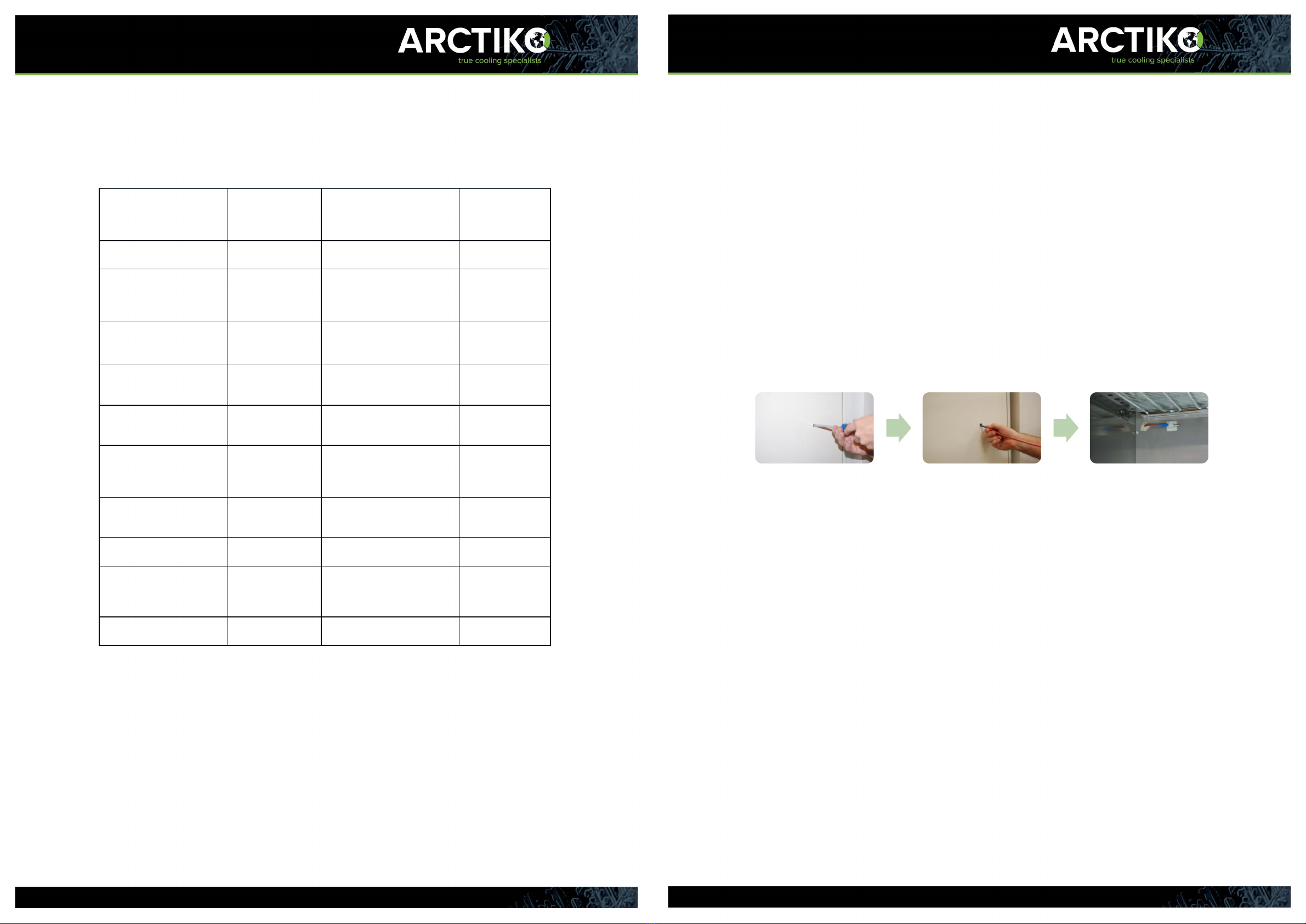
Getting started
During the initial startup and continuous usage of the appliance, the following
procedures shall be followed.
1. Plug the power socket into a dedicated outlet. For correct voltage
requirement, follow the information on the rating plate.
When started, let the appliance cool for 24 hours before placing any
products into it.
2. When the appliance initially starts up, the buzzer alarm may sound. This is
normal. You can accept the alarm on the display.
3. This appliance has been set to operate at -80°C from the factory.
4. Check the functionality of the light by opening the door.
5. Once a thorough inspection of the appliance is completed, products can
be loaded into the appliance. Products should be pre-frozen when inserted
into the appliance, otherwise this can aect the cooling performance of the
appliance.

1312
Product description
The Intergraline range oers the best ultra-low temperature freezing with
high performance and stability. Standard features are noise reduction tech-
nology, dual cooling system, VIP panels, air flow control, filter-less construc-
tion for less maintenance, low noise level, low energy consumption, low heat
dissipation and excellent temperature stability.
The compressors and cooling system is located in the top of the
appliance for easy maintenance and access, ergonomically correct work
position and less generation of heat in your working area.
All appliances are equipped with a vacuum valve and a key lock on the door.
Cabinet description

1514
Cabinet description
Never install probes through the door as this will deteriorate the
functionality of the door gasket, increase the ice build-up and aect the
temperature inside the appliance.
Probes and access ports
As standard, the appliance is equipped with a temperature probe inside the
chamber. The probe monitors the temperature in the chamber and controls
the operation of the compressors.
The main probe also controls temperature alarms. It is possible to connect
two dierent probes to the unit in order to monitor the temperature dierent
places in the appliance. You can change the settings on which probe is the
main probe.
To install more probes, you can use the premade access port(s) on the back
of the appliance. Carefully push a screwdriver or similar through the holes.
Always seal the holes with putty on both sides of the hole.
1. Top panel Compressor
compartment lid,
fitted with control
panel.
12. Castors 2 pcs. in front with
brake, 2 pc. back
without brake.
2. Display See “Display”. 13. Portholes See “Probes and
portholes”.
3. LED light Secure work light. 14. Evaporators Provides a
constant
temperature in
each compartment.
4. Door switch Monitors the door
openings and
control the lights.
15. Cover for noise
reduction and air flow
management
5. Probe See “Probes and
portholes”.
16. Remote alarm
connection
For connecton of
additional alarm
equipment.
6. Door handle with
lock
For easy opening,
closing and locking
the door.
17. Top panel latch For opening and
closing the top
panel.
7. Heated door frame Prevents ice build
up on door.
18. Compressor
compartment
The compressor
compartment is
located in the top
of the unit.
8. Inner doors Removable inner
doors.
19. *Racks and boxes Optional
equipment
(racks and boxes).
9. Vacuum valve Equalizes the
pressure in the unit.
10. Adjustable shelves Shelves that are
easy to adjust.
11. Fixed shelf This shelf cannot
be adjustet.
Dual cooling technology
Our Intergraline models ULUF P390/P500/P610/P820 with dual cooling
system. The dual cooling system oers two independent cooling
cycles and oers optimal security of your stored products in the unlikely event
of a failure in one of the cooling cycles. In case of failure, the other cooling
cycle will serve as a backup, guaranteeing that your stored products will be
kept at a safe temperature.
Filterless construction
Arctiko’s dual compressor system is designed as a filter-less system, which
prevents malfunctions caused by dust building up in the filter. This minimizes
the maintenance of the cooling system and secures a more stable operation.

1716
Remote alarm contact
The remote alarm contact is located on the backside of the appliance.
Vacuum valve
The vacuum valve helps equalizing the pressure inside the appliance, which
allows the user to open the door without waiting for hours.
Display
Easy and user-friendly control panel, with a 6-key resistive keyboard. You
can access a variation of settings, in order to adjust your unit for your exact
needs. A 4GB microSD is provided as standard, installed internally for
recording functional data every 30 seconds with a memory capacity of about
10 years.
In the single temperature configuration two types of Home Page are
provided: EASY or SCIENTIFIC. The external ESCAPE key selects one mode
or the other. The header shows the MACHINE_NAME (in the example
LABORATORY) that can be edited from the SETTINGS MENU.
Keyboard

1918
Info events
Door Warning
Action Icons Temperature alarms

2120
Failure events
NOTIFICATION OF PREVIOUS ALARM
To accept a failure, press the center of the screen.
Compressor Failure Alarm
The controller is equipped with a compressor failure detection feature.
If the controller detect an unusual temperature profile on one of the
compressors it will disable that compressor and activate an alert on the
controller. The other compressor will keep running.
To reset the alarm and reenable the compressor; accept the alarm and turn
the unit o and on again. During pulldown this alarm may be activated. If this
happens please reset the alarm. If the alarm keeps reoccuring please contact
your distributor or Arctiko service for help.
12
19.8
cooling
COMPRESSOR FAULT
HIGH TEMP. AFTER BLACKOUT
LOGIC FAILURE
COMPRESSOR FAULT
k1
1 <-> 2
19.8 c
0 m
k1
To accept a failure, press the center of the screen.
COMPRESSOR FAILURE ALARM
OCCURED
COMPRESSOR FAILURE ALARM
UNRESOLVED

2322
Outcome frames
The outcome frames will be accompanied by a long beep.
Warnings
To accept a warning, press “ ”.
DOOR OPEN

2524
How to turn on the device How to turn o the device
Press “Menu key” to access “Menu user”.
Press and hold “Standby” to turn o the
device (put in standby mode).
Press on the screen and hold, to turn on the
device.
If password protection is enabled type pasword
and press “Enter” ,
If password protection is enabled type pasword
and press “Enter” ,
Menu user
- STAND-BY
- SETPOINT
- LIMITS
- ACCESS LIST
- ECOMODE
- EVENTS
- GRAPHICS
- DEFROST
- SETTINGS
- SERVICE
press and hold to turn o the controller
change the temperature setpoint
set the high/low temperature limits and alarm delay
access log
set the ECOMODE parameters
displays the alarms and failures recorded
displays the daily temperature graph from calendar
start the defrost and displays temperature and time phase
(defrost function not available on Intergraline range)
access to MENU SETTINGS
access to MENU SERVICE

2726
How to change the setpoint How to change the alarm limits
Press the “Menu key” to access the menu.

2928
Access list Ecomode setting
KEY FUNCTION

3130
Event list
If the event list is empty, the icon above will be
shown.
Shows number of pages with
events. Press or to
change page.
Graphs
SCROLLING THE FRAPH AND ENABLING THE TRACES
REPRESENTATION CRITERIA

3332
Menu settings
- DATE/HOUR
- DISPLAY
- PASSWORD
- BACKUP
- CARD FORMAT
- UPDATE
- CLOUD
- SMS SETUP
- LANGUAGE
- MACHINE NAME
set the clock device
set the configuration of panel display
set the three levels of passwords
ADMINISTRATOR - USER - SERVICE
start download data through USB port
erase the data recorded
read and send setup files
set the LAN configuration
edit the telephone numbers where to send the alert messages
set the language of user interface
edit machine name by alphanumeric keyboard
How to set date/hour
Press select to move the highlight and +/- to change the value. To confirm
press “Enter” .
The system clock does not automatically manage the Summer time.
The connection towards the Cloud refers to the transparent UTC at the
nation time conventions.
The navigation on the VELEX Cloud refers to the zone time conventions if
the device used foresees its automatic management.
Language
KEY FUNCTIONS

3534
Pasword settings
The passwords are used for limiting access to certain areas in the menus.
There are 3 levels of access:
User(s): For setting basic parameters and turning the appliance on or o.
By default there is no password set.
Admin: For setting more advanced parameters and for managing users.
The default password is “111”.
Service: For accessing the service menu.
The service settings are reserved for qualified Arctiko service personnel.
By entering the admin password both the admin and user passwords can be
changed.
The passwords can be deactivated by setting them to “000”.
By entering the multiuser menu, multiple user accounts can be setup. This is
useful for tracking which user changes parameters or turns the appliance on
or o.
These individual user accounts can be named to easily dierentiate between
them.
Alarm test
Machine name

3736
Default settings
DDeessccrriippttiioonn
UUnniitt
DDeeffaauullttsseettttiinngg
Setpoint
°C
-80,0
LLiimmiittss((AAllaarrmmss))
Low temp.
°C
-99.0
High temp.
°C
-65.0
Delay
Minutes
15
Door
Seconds
40
Ecomode
OFF
DDiissppllaayy
Screensaver
Hours
0
Buzzer
ON
User password
Deactivated by
default
Admin password
111
The backup menu transfers the thermoregulation data on usb pen.
Pressing the backup icon shows the usb-pen insertion request frame with
20-second time-out. If the usb-pen has been recognised, the setting page
of the months to download is displayed, otherwise the display goes back to
the SETTINGS MENU.
The up/dw keys increase/decrease the number of months to transfer;
pressing the enter key starts the data download with the progress bar; at the
end, it goes back to the setting menu. The escape key leads to the settings
menu without transferring the data.
Data download
Attention!
Do not remove the USB drive while transferring data. Wait for the “V” icon to show
before removing the drive.

3938
Open and process data on a computer
You can transfer the data to a computer in order to analyze, process or
forward information. The program “THERMO CONVERTER” is needed to
transfer the data. The program can be obtained by contacting your Arctiko
distributor.
2. To convert the data, open the program “Thermo Converter”.
To convert the file press the “ DAT TO CSV CONVERT” button.
1. Insert the USB drive with the loaded data in a computer.
3. Open the file by following the path: VLX > BACKUP >
R00000 (serial number of the appliance)> 201807(year and month).
Choose the desired file and press “Open”.
Open
Open
4. When the convertion is complete, a window with the message
“Succesful operation” will appear. Press “OK” to continue.
Other manuals for ULUF P390
1
This manual suits for next models
3
Table of contents
Other Arctiko Freezer manuals

Arctiko
Arctiko ULUF User manual

Arctiko
Arctiko CRYO 170-0 User manual

Arctiko
Arctiko LCF 100 User manual

Arctiko
Arctiko CRYO 170-0 User manual

Arctiko
Arctiko LTFE 310 User manual

Arctiko
Arctiko SF SERIES User manual

Arctiko
Arctiko LTF 535 User manual

Arctiko
Arctiko Integraline ULUF P10 User manual

Arctiko
Arctiko ULUF 120 User manual

Arctiko
Arctiko UPUL 580 User manual