Arctiko UPUL 580 User manual

OPERATING INSTRUCTIONS
UPUL 580

2
INDEX ...........................................................PAGE
Before using the freezer...............................................................3
Safeguarding the environment ....................................................3
Precautions and general recommendations ........................................3
Installing the freezer..................................................................4
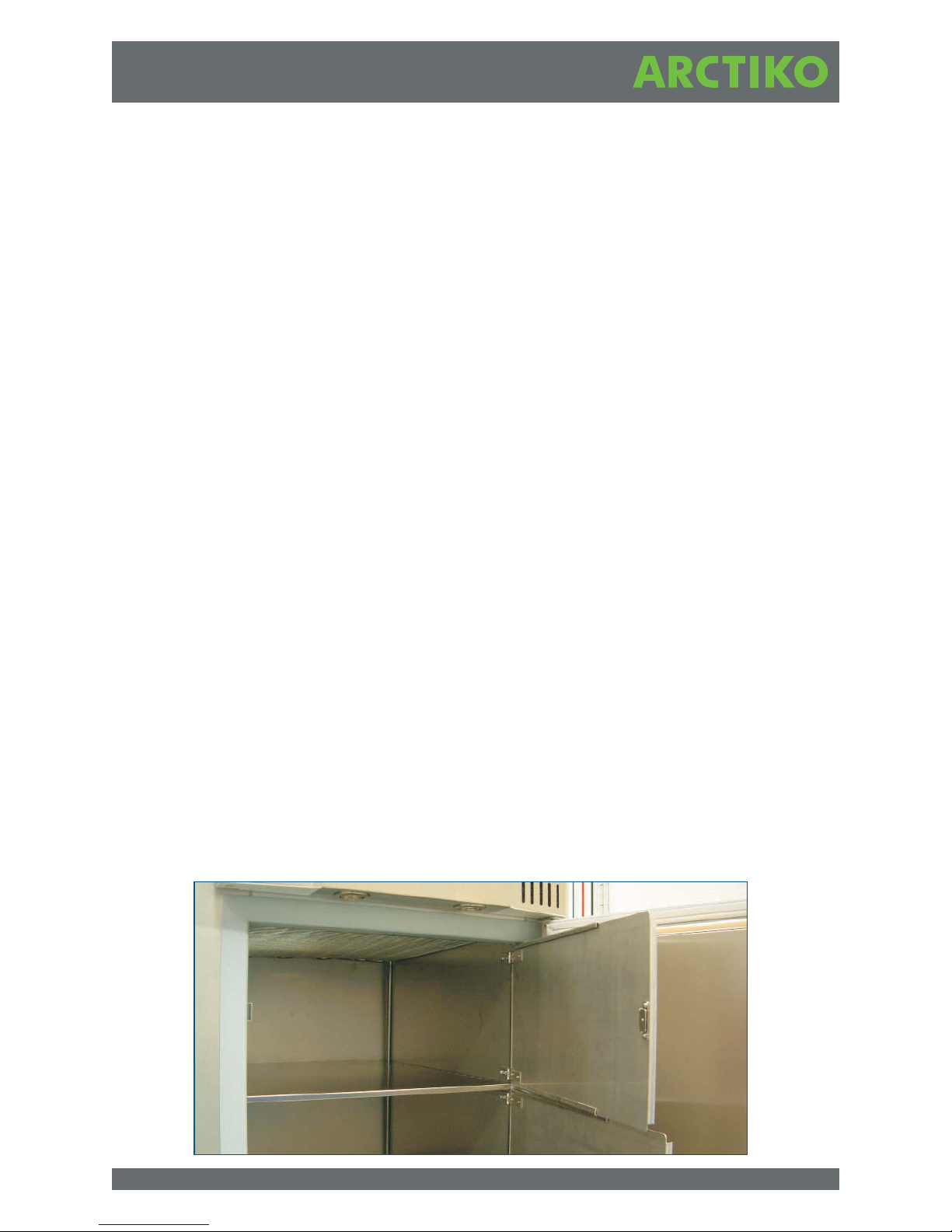
Inner doors ......................................................................5
Electrical connection .............................................................5
Before commissioning ...........................................................6
Start procedure ......................................................................6
Starting up the freezer............................................................6
Disconnecting the appliance ......................................................6
Functional description of the control panel .........................................6
Access code .....................................................................6
Turn/Push button.................................................................7
Main switch............................................................... 7
Menu selection .................................................................. 7
Adjustment of settings ...........................................................7
Operation description ............................................................ 7
Usage....................................................................8
Setup ....................................................................8
Manual mode ....................................................................8
Calibration of sensor ............................................................. 8
Alarm ....................................................................9
Explanation of Alarms............................................................10
The cooling system..................................................................10
CO2 Back Up ........................................................................10
Service with for - °C freezers..................... .....................
Filling procedure ................................................................11
Relocating or moving the freezer ...................................................11
Cleaning and maintenance of the freezer ...........................................11
Spare parts .........................................................................12
Disposing of the freezer .............................................................12
MENU OVERVIEW ...............................................................13-17
CONNECTION DIAGRAM ........................................................ 18-19

IMPORTANT
Before using the freezer
For safety reasons, the instructions should be read before the freezer is commissioned.
The operating instructions should always be available and accessible to personnel!
The appliance concerned complies with the following directives and standards except for refrigerant
amount:
Low Voltage Directive 2006/95/EEC
Electromagnetic Compatibility Directive 2004/108/EEC
Only use the freezer for its specific purpose.
Safeguarding the environment:
1. Packing
The packing material is entirely recyclable and marked with a recycling symbol.
Please follow the local regulations for scrapping.
2. Appliance
The freezer is made from recyclable material. Disposal of the appliance should be carried out according to
local environmental regulations.
Make the appliance unusable by cutting of the power supply cord. Please deliver the appliance to an
authorised centre for recovery of refrigerant.
Information
This appliance contains a mixture of various refrigerants. For more information please refer to the rating
plate affixed to the freezer.
Precautions and general recommendations:
WARNING: Keep ventilation openings, in the appliance enclosure or in the built-in structure, clear of
obstruction.
WARNING: Do not use mechanical devices or other means to accelerate the defrosting process, other than
those recommended by the manufacturer.
WARNING: Do not damage the refrigerant system.
WARNING: Do not use electrical appliances inside the freezer storage compartment, unless they are of the
type recommended by the manufacturer.
•Always keep the keys in separate place and out of reach of children.
•Before servicing or cleaning the appliance, unplug it from the mains or disconnect the electrical
power supply.
•The power supply cable may only be replaced by an authorised person.
•Frost formation on the interior wall and upper parts is a natural phenomenon, and therefore the
freezer should be defrosted during normal cleaning or maintenance.
3

Appliance with flammable refrigerant
As the appliance contain a mixture of refrigerant, which are flammable, it is essential to ensure that the
refrigerant pipes are not damaged.
Operating Instructions
For safety reasons these operating instructions should be read before the freezer is commissioned. The
operating instructions should always be available and accessible to personnel!
The drawings and symbols in these operating instructions are for safety purposes when commissioning and
using the freezer.
Instruct personnel in the use of the freezer (the temperature is below -85°C). There is a risk of frost-bite if
the contents or parts of the inner container are touched!
In the event of breakdown or irregularities contact professional instructors or repair technicians immediately.
Installing the Freezer
1. You will find 3 different plugs for the installation. Use the plug suitable for your electrical connection.
2. Always allow an authorised electrician to install the freezer (read the operating instructions).
3. The freezer should be located in a cool, dry place out of direct sunlight. The freezer gives off a great
deal of heat when in operation. If the ambient temperature is too high there is a risk that the freezer
will not operate correctly. It is recommended that the room be ventilated so that the room
temperature does not exceed 20°C. Class N.
4. Place the freezer on a solid and flat substrate. This will eliminate any vibration and irritating noise.
The freezer should be placed with at least 10 cm free to the sides, at least 15 cm free at the back.
The installation should be fused with a 10A fuse.
4
figure 1

Inner doors
NOTE
The inner doors should be used at all times. Make sure to close them tightly. (figure 1)
The manufacturer is not responsible for damage to the freezer caused by failure to do so.
Electrical Connection
The machine meets current EU directives. Low voltage 2006/95/EEC.
Electromagnetic compatibility 2004/108/EEC.
The machine should be given extra protection in accordance with Electricity Supply Regulations in order to
protect the user against dangerous electric shocks in the event of faults.
If the switch is for a three-pin plug, a three-pin plug should be used and the conductor with yellow/green
insulation connected to the Earth terminal.
Data regarding voltage and absorbed power/current is given on the rating plate.
Electrical connection must be made in accordance with the local regulations.
For installation see wiring diagram (page 18 - 19).
Warning
Regulations require that this appliance be earthed:
The manufacture declines all liability for injury to persons or animals and for damage to property resulting
from failure to observe the above procedures and reminders.
If the socket and plug are not of the same type either the socket or the plug must be replaced by a qualified
electrician.
Under no circumstances use extension leads or adaptors.
1. The freezer should be connected by an authorised electrician or by the company that sold the
freezer. Incorrect installation may damage the freezer.
2. Place the freezer on a flat floor that can bear the weight of the freezer.
3. The electrical installation should be earthed.
4. Do not use extension cables. Connect the freezer directly to a fixed installation. If the freezer is
connected to a long extension cable there is a risk that the cable will become hot.
5. The freezer should be placed in a dry location. Do not allow water to come into contact with the
cabinet. Water entering electrical parts may cause short-circuiting.
6. In the event of functional or electrical irregularities, please contact an authorised service engineer.
5

Before Commissioning
Clean the freezer both inside and out using a damp, wrung out cloth. Dry with a dry cloth.
Start Procedure
Put the plug in the socket.
The digital thermostat/thermometer will start to flash. The thermostat is pre-set by the producer. The freezer
should run for at least 6 hours before the thermostat is changed to allow for stabilisation of the cooling
system.
The alarm function will not start before the temp. reached temperature set point = -83°C for the first time.
Change of alarms and of the set-points - see table for parameters.
Starting Up the Freezer
Start the freezer. Set the digital thermometer at the temperature required. It will now take about
6-10 hours before the set temperature is reached.
The freezer should be cooled down empty.
When filling the unit with racks/boxes, make sure to pre-cool them in order not to effect the inside
temperature of the unit.
Disconnecting the appliance
Electrical disconnecting must be possible either by unplugging the appliance or by means of a double pole
switch located up-line from the socket.
Functional description of the control panel
Access code
The access code 344 is to be used by the technician to enter the following menus
(see menu overview page 13):
MODE MENU
ALARM MENU
SERVICE MENU
Indicator LEDs
The LMC 260 has two LEDs at the left side of the display. They light up as described below:
The display backlight is always switched on unless the controller is in battery mode. In battery mode the
backlight will be switched on when the button has been pressed or turned. It will then be turned off after
approx. 20 seconds. If the turn/push button has not been activated for 5 minutes the main menu will be
shown. Active alarms will result in flashing lower LED and backlight. Inactive alarm will only make the lower
LED flash.
6
OFF Green Red Green flash Red flash
Upper LED -- Power OK -- -- --
Lower LED -- -- -- -- Alarm
6

Turn/Push button
The LMC 260 control panel is controlled by turning / pushing the button at the right hand side of the display.
The button has three functions:
Turn CW :Next Menu or increase set value
Turn CCW :Previous Menu or decrease set value
Push :Select Menu and accept edited set value
Main switch
The LMC 260 control panel has a main switch. It is located at the left hand side of the display and has two
functions:
Up :The freezer is in Standby Mode. Works like an OFF function but the temperature readout is
active.
Down :The freezer is in Auto Mode. Works like a normal ON switch, where the controller controls the
freezers temperature, the CTS signal and alarm system.
Menu selection
The menu can be changed by turning the turn/push button. The menus shown with an arrow in the lower
righthand corner, have sub menus. The submenu is activated by pressing the button once. When turning the
button the submenu items appear. Pressing on the item “Menu Up” exits the submenu.
Adjustment of settings
Turn the button until the required parameter value is shown in the display. Press once to edit the value. It
will now flash. Turn the button to adjust the parameter. Press the button to accept the value or cancel it by
not pressing the button for 5 seconds.
Menu overview
See menu structure page 13 - 17.
Operation description
Operating mode and status
The user selects the operating mode of the system with the switch at the left side of the display:
The actual status of system is shown in upper line of the main menu:
7
Operation Description
STANDBY The temperature in the freezer is shown but there is no regulation/control
AUTO The LMC260 controls the temperature in the freezer
Status Desription
STANDBY Freezer is turned off. No active functions except the actual freezer temperature
FREEZER Normal mode. Temperature regulation is active.
TEST User test active
T1 OPEN Temperature sensor for the freezer is open
T1 SHORT Temperature sensor for the freezer is closed
T2 OPEN Temperature sensor for the room is open
PWR FAIL There is no mains on and the main switch is in auto mode
DOOR Door is open
ROOM TEMP Room temperature too high
T LOW The freezer temperature is too low
T HIGH The freezer temperature is too high

Usage
Setup
The freezer must be set up by an authorized person. In the settings menu the correct code must be entered
so that the items below become visible.
1. SETPOINT : The temperature that the controller is set to achieve [SetPoint]
2. T DIFF : The difference between the SetPoint and the temperature that causes the fan and
compressor to restart
3. ALARM LO : SetPoint [value] set off Alarm Lo
4. ALARM HI : SetPoint + [value] set off Alarm Hi
5. AL.DELAY : Delay before Alarm Hi/Lo is activated
6. MAX ROOM : Maximum room temperature before room temp alarm is given
7. CPRTIMER : Minimum time between each compressor startup
8. CHANGE CODE : Change the access code
Usage
When the freezer has been setup and the freezer is in auto mode, it will operate in accordance with these
settings. When settings are changed the freezer will use the new settings immideatly after.
The controller will now try to cool the freezer to the SetPoint. When this is reached the fan and compressor
will stop. When the freezer temperature rises above SetPoint - TDiff they will start up again.
Please note that the fan will run 15 seconds before and after the compressor.
Manual mode
A person with the correct access code will be able to operate the controller manually. Select MODE-
>MANUAL to put the freezer into manual mode. From SERVICE->MANUAL->[Menu] the operator is now
able to turn on/off the compressor, fan, light, CTS, Battery Charge and Buzzer. When manual control is
finished the operator must select MODE->AUTO again to cancel manual mode. There are no regulation
or safety features of any kind active in manual mode. Please note that this mode is only for
trouble shooting.
Note that the control system does NOT return to AUT-mode automatically.
Calibration of sensor
The temperature sensor of the freezer can be calibrated. Before this the temperature must be stable.
Therefore this menu item is not active until the freezer has settled on the SetPoint for one hour as a
minimum.
Description of the calibration procedure.
Enter a calibration value in SETTINGS -> CALI. This value represents the offset from the SetPoint.
The LMC260 now controls the freezer according to SetPoint +/- this value.
8
service and

Example
SetPoint is adjusted to -83°C. The reference thermometer indicates -85°C. To correct this enter -2°C and
the freezer will cool down to -85°C. The LMC260 will now operate with the new correct value.
Resetting this value to the factory setting is done by setting the CALI value to 0°C.
Alarm
Alarm list
Alarm system
The upper LED will flash when there is an alarm. The operation status will change to "ALARM". In the sub
menu "View" the reason for the alarm and the alarm code can be read. The alarm will change from actve to
inactive when the reason for the alarm has been removed.
After entering the access code the “Alarm Menu” can be activated. Delete an inactive alarm from the list by
pushing the Turn/Push Button. Active alarms cannot be acknowledged.
In the “ALARM LOG” sub menu the last 16 alarms can be read.
If the mains voltage is interrupted the mains voltage will be checked continously.
9
Alarm no. Alarm Alarm text display Limit Sound
AL10 T1Open T1 OPEN -90 °C X
AL11 T1 Short T1 SHORT 149 °C X
AL12 T2 Open T2 OPEN -90 °C X
AL30 Power Fail MAINS OFF - X
AL31 Door open DOOR Door opeen > 15min X
AL32 TRoom ROOMTEMP Room temperature too high X
AL33 TLow T LOW Freezer temperature too low X
AL34 Thigh T HIGH Freezer temperature too high X
AL40 Room Sensor T.SENSOR
AL41 Door Sensor D.SENSOR
AL42 No Sound in
Test
DNUOS ON
AL02 SW error SOFTWARE
AL04 Initialisering INIT
AL05 Database DATABASE
AL06 Watchdog WATCHDOG

10
Explanation of Alarms:
AL10 - T1 OPEN : Temperature sensor to freezer interrupted
AL11 - T1 SHORT : Temperature sensor to freezer short circuited
AL12 - T2 OPEN : Temperature sensor to room interrupted
AL30 - MAINS OFF : No mails supply to the freezer
AL31 - DOOR : Dor was open for more than 5 minutes
AL32 - ROOMTEMP : Room temperature too high
AL33 - T LOW : Freezer temperature too low for more time than alarm delay
AL34 - T HIGH : Freezer temperature too low for more time than alarm delay
AL40 - T.SENSOR : User test fault at room temperature sensor
AL41 - D.SENSOR : User test fault at door sensor
AL42 - NO SOUND : User test fault at buzzer
The Cooling System
The vaporiser is built into the shelves of the inner container. They will be approx. -85°C, so there is a risk of
frostbite if they are touched. Always use thermal gloves when touching the contents of the freezer.
The condenser is placed on top of the cabinet behind the control panel.
Thermostat with digital display: once the freezer is cooled down, the set temperature and the temperature
shown will be the same.
CO2 Back Up
2
4 x port holes are prepared for CO back up, and an injection tube (see separate enclosure) can be inserted
2
from the top of the unit (remove kit). Make sure that pressurized CO escape from the gaskets or pressure
valve.
Service with for - °C freezers
Note that the EP88 gas can only be filled from a bottle containing a measured amount. Normal procedures
used in conjunction with other refrigerants cannot be used.
Further note that the freezing capability is very dependent upon filling the entire contents of the bottle into
the system. Freezing capability is also very dependent upon the temperature of the EP88 and whether it
has been still for a long period of time. The temperature of the service bottle must be between 8 and 14
degrees and the contents mixed by shaking the bottle 10-15 times.
In order to carry out the service procedure correctly, it is necessary to use a capillary pipe with mounting
screws between the bottle and the filling station instead of a normal filling hose. The service technician may
do this by using the mounting screws of a normal filling hose onto a capillary pipe.

11
Filling procedure:
•Empty the system and evacuate to 2 mbar. Evacuation must be performed at two places in the
system; both from the filling pipe and from the pipe mounted on the pressure side of the compressor.
•Mount the capillary pipe with mounting screws between the filling station and the service bottle.
•Unlike with other refrigerants, the service bottle must be turned tap-down.
•Commence filling.
•The compressor will start after approx. 10-15 seconds of filling.
•The bottle is empty when the pressure falls to 1bar and must be shut immediately. Immediate
shutting of the bottle is very important to prevent the fluid being pushed back into the bottle.
•Close the system.
Relocating or Moving the Freezer
Never leave the freezer to others without instructing those people in its use and the safety regulations
described in the operating instructions. Always let an authorised electrician install the freezer. (Remember to
wait for one hour before restarting it).
If the freezer and its electrical parts are reconstructed, the guarantee and safety regulations shall cease to
apply.
•If the freezer does not work: call an authorised servicing engineer!
•Contact the distributor or an authorised service repair shop!
•It is not recommended to lay down the unit. Please let the unit rest in vertical position for minimum 12
hours before start up.
Cleaning and Maintenance of the Freezer:
•Ice will form on the inner doors of the freezer. This ice should be removed with a scraper at regular
intervals. (Remember safety gloves).
•Ice on the inside of the cabinet should be removed as required. Take the contents out of the freezer.
Pull out the plug and leave the door open until the ice can be removed. (Remember safety gloves).
•Dry the inner cabinet and shelves with a cloth until it is not damp any longer.
•For external maintenance use stainless steel polish.
•Ice formed on the inside of the door should be removed with a wooden/plastic scraper. This ice will
build up because of the low temperatures inside the cabinet, and if it is not removed it will cause the
door to open.
•Cleansing agents containing chlorine or compounds of chlorine as well as other corrosive means
may not be used as they might corrode the stainless panels of the cabinet and the evaporator
system.
•The compressor compartment and in particular the condenser must be kept free from dust and dirt.
This is best done with a vacuum cleaner and a brush.
Do not put bottles containing carbonic acid or inflammable products in the freezer.
Disposal and scrapping of the freezer: Remove the lock, so that there is no risk of children getting locked in
the freezer whilst playing.

12
Note
Unplug the appliance before carrying out maintenance.
Do not use abrasive products; stain removers (e.g. acetone, trichloroethylene) to clean the appliance.
Spare parts
When ordering spare parts that you can easily fit yourself, please give unit type number and the function of
the part(s) concerned.
Disposing of the Freezer
To prevent harmful environmental effects, contact the distributor and ask where the freezer should be
delivered.
Remove the locking function so that children cannot be locked in the freezer whilst playing.
You can obtain information on the disposal of refrigeration appliances from:
•Your supplier
•Authorities (The Local council, Ministry of the Environment, etc.)

13
MENU OVERVIEW
Test for verifying the functionality of
the room temperature controller.
The user has to open the door in
order to test the door contact.
Test of door contact finished. The
user has to close the door.
Test of noise. The user has to
confirm with yes or no.
Test finished. Any errors will be
shown on the display with “failed” in
stead of “success”. The errors are
shown in the alarm log.
Test menu will be active after
pushing the button for 10 seconds.
Can also be done by the user.
This menu is applied by the
technician to decide whether the
freezer should run automatically or
manually.
View menu shows set point and
the number of alarms.
In this part of the menu the
technician records the set point,
limits for the alarms, etc. Using this
way, the user can access the
calibration (system).
The alarms have to be approved
by the technician after the cause of
the alarm has been removed.
Shows a list over the last 15
alarms in the system. Active as
well as inactive alarms are shown.
Service menu is applied by the
technician / authorised personnel.
For set up and service.
-80°C

14
In this menu the technician can
programme the freezer to run
automatically or manually.
Back to previous menu.
Shows current set point.
Shows how many alarms are saved
in the alarm log.
Back to previous menu.
-80°C

15
Back to menu.
If the freezer has not been programmed on
set point in more than one hour, the display
shows “not ready”. Otherwise the
calibration menu is shown.
The technician can set the code, which
gives access to the service menus.
The technician can programme the set
point of the freezer.
The programming of the temperature
hysteresis. Compressor starts at TSet +
TDiff and is turned off at TSet.
The programming of the lowest alarm limit.
TA1Lo + TSet= Alarm
The programming of the highest alarm
limit. TA1Hi + TSet = Alarm
The delay of the abovementioned alarms
starts.
The technician has to programme the
maximum allowed room temperature
before the room temperature alarm is
activated.
The programming of the shortest time
which is allowed between every
compressor start. Depends on the type of
the compressor.
Allows you to change the code.
Language menu for the menu system. The
text which describes the language is
always on the same language. For
example: (English, Dansk, Deutsch…)
Can be bought as an option.
Back to menu.
-80°C

16
Back to previous menu.
Alarm ## shows the location of the
alarm in the log. Text shows a
describing text with reference to the
alarm.
Shows the last 15 alarms.
Back to previous menu.
Shows which software version is
installed in the unit.
Shows the total running hours of
compressor.
Shows the total running hours of the
ventilator.
Menu for manual running of the
freezer.
Back to previous menu.

17
Back to previous menu.
Manual running of the compressor.
Manual running of Fan.
Manual running of light.
Manual running of CTS.
Test of Power Sence Relay. When
this relay runs out it is discovered by
D12.
Test of battery and test of Battery
Disconnect Relay.
Manual running of Battery Test-relay.
Manual running of audible alarm.
Back to previous menu.

18
CONNECTION DIAGRAM

19

LAMMEFJORDSVEJ 5
DK-6715 ESBJERG N
DENMARK
TEL. +45 70 20 03 28
FAX. +45 70 20 03 29
INFO@ARCTIKO.COM
WWW.ARC T IKO.COM
WWW.ARCTIKO.COM
50 80 014-xx-GB
Other manuals for UPUL 580
1
Table of contents
Other Arctiko Freezer manuals

Arctiko
Arctiko ULUF P390 User manual

Arctiko
Arctiko SF SERIES User manual

Arctiko
Arctiko ULUF 120 User manual

Arctiko
Arctiko LTF 535 User manual

Arctiko
Arctiko ULTF 80 User manual

Arctiko
Arctiko CRYO 170 User manual

Arctiko
Arctiko CRYO 170-0 User manual

Arctiko
Arctiko LTFE 140 User manual

Arctiko
Arctiko Integraline ULUF P10 User manual

Arctiko
Arctiko CRYO 170-0 User manual