8/17 5084132-03
3Operational Qualification
The Operational Qualification is intended to verify the function of the appliance and its readi-
ness for operation.
The OQ is concluded if all acceptance criteria are fulfilled. If any deviations are found during
the qualification, such must be corrected and thereafter approved.
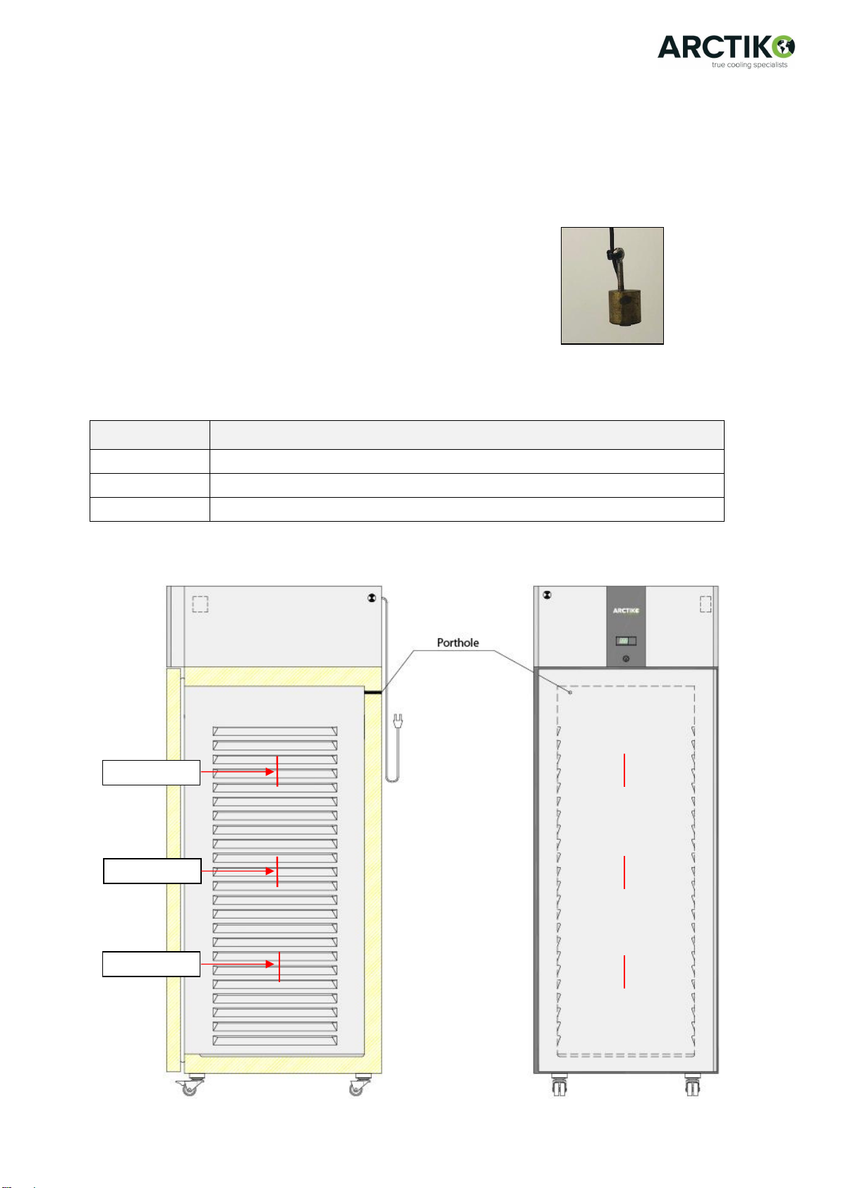
Check and verify the following parameters and fill out the below table. We recommend that the
parameters are checked app. once a year.
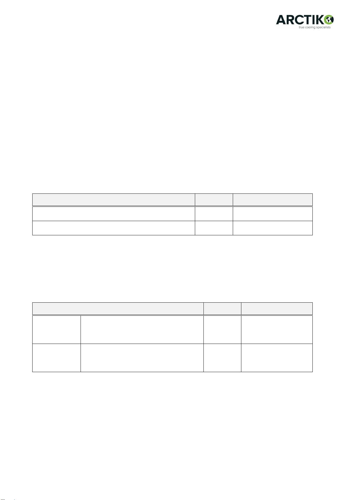
3.1 Parameter verification and adjustment
SETTINGS
LRE 700
LRE 1400
SETTINGS
LFE 700
LFE 1400
SET VALUE AND
NOTE THE VALUE
(PS)*22 22
(St) +4 -20
hysteresis (rd) 2 2
defrost (dl) N/A 6 hrs.
ture alarm by-
pass time after
defrost and door
open (d8)
0 0
after door open
(d8d)
2min. 2 min.
(AL)**4 10
(AH)**5 8
alarm delay (Ad) 5 min. 5 min.
*Use of password 22 will access all parameters. Password 0, which is stated in the user manual, will only
access a selected number of parameters.
**AL and AH are relative thresholds to the set point. The set values must be positive values.
Examples
Set point: +4°C
High. temp. alarm (AH): 5
AH alarm activation: +9°C
Set point: +4°C
Low. temp. alarm (AL): 3
AL alarm activation: +1°C
Set point: -20°C
High. temp. alarm (AH): 7
AH alarm activation: -13°C
Set point: -20°C
Low. temp. alarm (AL): 6
AL alarm activation: -26°C