WARNINGS AND LIMITATIONS
Our devices use high quality electronic components and plastic materials that are
highly resistant to environmental deterioration.
However, after 10 years of continuous operation, it is advisable to replace the
devices in order to minimize the risk of reduced performance caused by external
factors.
Ensure that this device is only used with compatible control panels.
Detection systems must be checked, serviced and maintained on a regular basis to
confirm correct operation.
Smoke sensors may respond differently to various kinds of smoke particles, thus
application advice should be sought for special risks.
Sensors cannot respond correctly if barriers exist between them and the fire location
and may be affected by special environmental conditions.
Refer to and follow national codes of practice and other internationally recognized
fire engineering standards.
Appropriate risk assessment should be carried out initially to determine correct
design criteria and updated periodically.
WARRANTY
All devices are supplied with the benefit of a limited 5 years warranty relating to
faulty materials or manufacturing defects, effective from the production date indicat-
ed on each product.
This warranty is invalidated by mechanical or electrical damage caused in the field
by incorrect handling or usage.
Product must be returned via your authorized supplier for repair or replacement
together with full information on any problem identified.
Full details on our warranty and product’s returns policy can be obtained upon
request.
ARGUS SECURITY S.R.L.
Via del Canneto, 14
34015 Muggia (TS)
Italy
EN 54-3:2001+A1:2002+A2:2006
Fire alarm devices - Sounders
* VC-BS-01
** VC-BSB-23W-01
** VC-BSB-23R-01
EN 54-23:2010
Fire alarm devices - Visual Alarm Devices
** VC-BSB-23W-01
** VC-BSB-23R-01
Type A - Intended for indoor use only
For use in compatible fire detection and alarm systems
Other technical data: see TDS-BSXXX held by the manufac-
turer
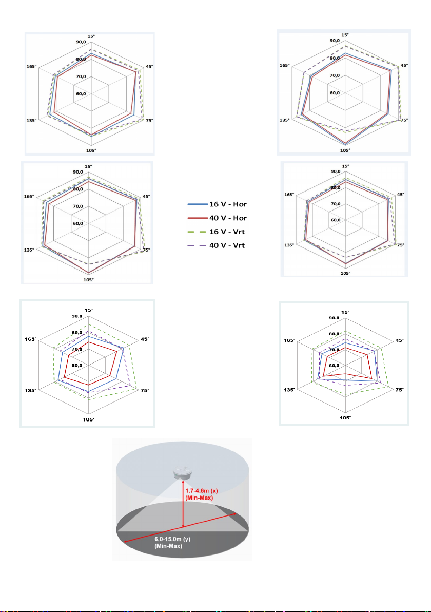
Category rating:
C 3 - 15 & O 4.5 - 15.2
VC-BSB-23W-01 (high power)
C 3 - 10
VC-BSB-23R-01 (high power)
C 3 - 9.2
VC-BSB-23W-01 (low power)
O 1.7 - 6.0
VC-BSB-23R-01 (low power)
Duration of operation: Pass
Provision for external conductors: Pass
Flammability of materials: Pass
Enclosure protection: Pass
Access: Pass
Manufacturer's adjustments: Pass
On-site adjustment of behaviour: Pass
Requirements for software controlled devices: Pass
Coverage volume: Pass
Variation of light output: Pass
Minimum and maximum light intensity: Pass
Light colour: White (VC-BSB-23W-01)
Light colour: Red (VC-BSB-23R-01)
Light temporal pattern / frequency of flashing: N/A / 0.5 Hz
Marking and data: Pass
Synchronization: Pass
Durability: Pass
Temperature resistance: Pass
Humidity resistance: Pass
Shock and vibration resistance: Pass
Corrosion resistance: Pass
Electrical stability: Pass
0051 8504
17 22
* BS0310CPR * BS0310UK
** BS0410CPR ** BS0410UK