Odom ECHOSCAN User manual

04/26/02 1 Revision 1.11
TABLE OF CONTENTS
INTRODUCTION............................................................................... 2
General .............................................................................................................2
Specifications ....................................................................................................4
INSTALLATION................................................................................ 5
System Components .........................................................................................5
Power Supply Considerations ...........................................................................6
Transducer Installation ......................................................................................7
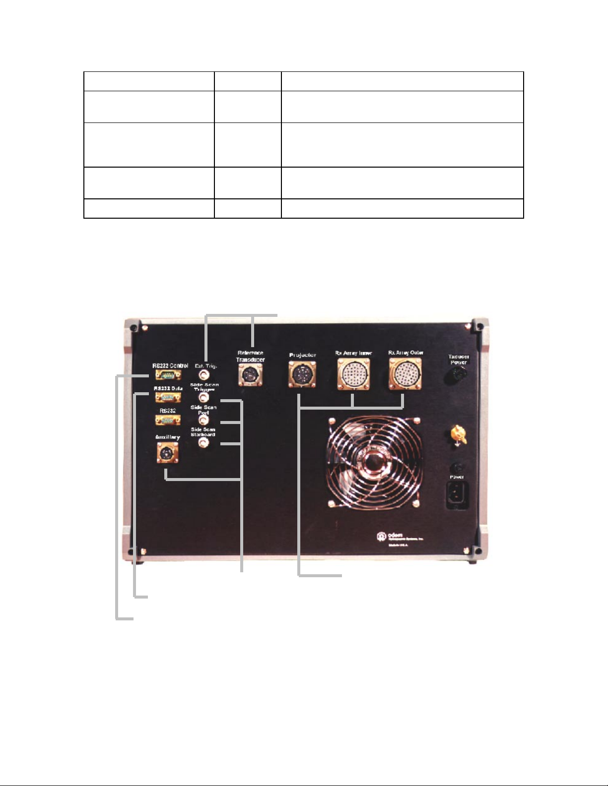
SPU Connections..............................................................................................9
CONTROLS AND INDICATORS .................................................... 11
SPU.................................................................................................................11
LCDU ..............................................................................................................11
Startup Screen ................................................................................................12
File ..................................................................................................................13
Display ............................................................................................................13
Setup...............................................................................................................14
Gain.................................................................................................................15
Digitizer Settings .............................................................................................16
Help.................................................................................................................16
Control Panel...................................................................................................17
OPERATION................................................................................... 20
Power-Up Procedure.......................................................................................20
Example Survey System Configuration ...........................................................21
HYPACK......................................................................................................21
ECHOSCAN Setup ......................................................................................21
HYSWEEP...................................................................................................25
Non-Standard System Configurations.............................................................26
COMMUNICATION CPU - Dip Switch Settings ............................ 29
MULTIBEAM CALIBRATION ......................................................... 31
Bar Check .......................................................................................................31
Referencing to a Single Beam Echo Sounder .................................................31
Combined Velocimeter and Single Beam Calibration......................................31
Flux Gate Compass Alignment........................................................................33
COMPUTER INTERFACE .............................................................. 34
Serial Output Strings .......................................................................................34
ECHOSCAN Output Simulators ......................................................................35
Side Scan Recorder / Processor Interfacing ...................................................36
EXTENDER CABLE WIRING ......................................................... 38
TRANSDUCER CABLES................................................................ 39
JUNCTION BOX WIRING............................................................... 42
HEADING SENSOR WIRING ......................................................... 44

04/26/02 2 Revision 1.11
INTRODUCTION
ECHOSCAN is a 200 kHz multibeam echo sounder employing physical
beamforming techniques to shape and steer 30 beams over a 90° coverage
sector. There are three major components in the ECHOSCAN system; the
Transducer, the Signal Processing Unit (SPU), and the Laptop Control / Display
Unit (LCDU).
General
The piezoelectric material used in the transducer design is PVDF
(PolyVinyliDene Fluoride). Each receiver has a sensitivity of -197 db (re 1
V/µPa) with sidelobes suppressed to greater than -30 db. The transducer
is hydrodynamic in shape to allow for minimum drag at high survey
speeds (in excess of 13 knots) without flow noise or cavitation. 30
independent beams fan out from the transducer to cover a swath equal to
twice the water depth. The transducer is positively buoyant for easy
recovery should it impact with floating debris. Provisions for housing
motion sensors and side scan elements are built right into the fairing.
Also built into every ECHOSCAN transducer is a separate, single beam
receiver that is used with a standard survey echo sounder, such as the
Odom ECHOTRAC, for shallow water applications or to provide a hard
copy of the vertical profile. This “reference” transducer is also used to
assist in calibration of the multibeam and provides a “hard copy” of the
traditional “bar check”.
ECHOSCAN will produce sounding densities ranging from 1 sounding
every 13 square meters to 7.5 soundings per square meter depending on
Figure 1
ECHOSCAN Transducer

04/26/02 3 Revision 1.11
selected Range Scale. Tilt angles up to 45° port or starboard are possible
for surveying structures such as breakwaters and dams. If the optional
motion sensor is installed, the tilt angle is sensed to within .05° and
automatically compensated.
Side Scan elements, mounted
along the bottom edge, are
included in every ECHOSCAN
transducer. Backscatter
imagery from the common 2.5°
PZT projector is received by the
two, 0.7° side scan receivers to
form a uniform, high resolution
beam pattern over the entire
swath.
The SPU contains 11 signal
processors, each independently
tracking and digitizing bottom
echo signals. The additional
board process side scan
backscatter imagery. All 11
boards are identical and
interchangeable (See Technical
Manual for details).
Real time data quality
verification is provided in the
form of a 3D display program
running on the LCDU. The
operator is presented with both
profile and trend information
and can access the gain and
power settings. The operator
also controls the number of
historical scan lines shown in
the 3D presentation. Both
bathymetry and side scan gain
and TVG settings are accessed
through the LCDU.
Other real-time control / display functions are described in section 3. The
“C” language program running on the LCDU may be ported over and
executed under the user’s operating system.
Figure 2
Signal Processing Unit (SPU)
Figure 3
Laptop Control/Display Unit
(LCDU)
Pull
Down
Menus
3D
Data
Display
Control
Panel

04/26/02 4 Revision 1.11
Specifications
Technical Specifications for the Odom ECHOSCAN Multibeam are as
follows:
• Acoustic Frequency ………………... 200 kHz
• Number of Beams ………………….. 30 (physically beam formed)
• Transducer Receive Elements …… PVDF
• Projector Configuration ……………. PZT, 256 element, curvilinear array
• Beam Pattern ……………………….. 3° at 3db Points (elliptical)
• Coverage Sector ……………………. 90°
• Acoustic Working Depth Range ...... 2-100 Meters (guaranteed), 2-200
Meters (theoretical)
• Output Update Rate ……………….. Depth Dependent (13/sec at 20 m
range)
• Output Resolution ……………….... 2.5 cm
• Roll / Pitch Accuracy ………………. 0.05° (w/ optional ODMS-05 sensor)
• Maximum Tilt Angle ……………….. 45° (self-calibrating w/ ODMS-05
sensor)
• Sidelobe Suppression .................... > -30db Per Channel
• Sensitivity................................…..... -197 db re 1 V/µ Pa
• Source Level ............................….... 225 db re 1 µPa at 1 Meter
• Preamp Noise ……………………… < 3db
• Ref. Transducer Beam Width .…… 9° at 3db Points
• Side Scan Imagery ………………… High Resolution, Analog
• Side Scan Beam Pattern ................ 110° x 0.7°
• Real-Time Data Presentation ……. 3D Perspective, profile “waterfall”
• Max Survey Speed ………………… Between 12 & 17 Knots (hull and mount
design dependent)
• Power Requirement .................…... 110/230 VAC, 50/60 Hz Optional 24
VDC, 75W
• Dimensions:
SPU ............................... 48.3 (w) x 26.7 (h) x 24.2 (d) cm.
Transducer ..................... 38.1 (w) x 26.1 (h) x 125.5 (d) cm.
• Weight:
SPU ......................…....... 13.6 kg.
Transducer ..................... 40.8 kg. (positively buoyant in water)

04/26/02 5 Revision 1.11
INSTALLATION
In addition to the primary components of the Odom ECHOSCAN (the SPU,
LCDU, and the Transducer), a full complement multibeam system requires, a
heading sensor (compass), a positioning system (normally a GPS receiver), and
a ship’s motion sensor. For ease of inter cabling, Odom supplies a Junction Box
(See Figure 4) to route signals to various units and sensors. For Example: The
ODMS-05 motion sensor is setup to receive GPS and compass information to
assist and optimize operation while in turns. The Junction Box is designed to
handle this and other data interchanges.
System Components
A diagram of the complete system is shown in Figure 4. The dashed lines
represent optional equipment and connections. A technical manual for
each sensor and component system is supplied with the ECHOSCAN.
SPU
LCDU
Junction
Box
Power
Supply
110VAC 24 VDC
ECHOTRAC
(Single Beam)
*
**
*
** Transducer
HPR
Side Scan
Processor
Data
Acquisition
COMAPSS
GPS
MB
**
**
*
COMPASS
GPS
ODMS-05
GPS
Compass
XYt
T
P
S
Projector
Beams 1-15
Beams 16-30
ODMS-05
ODMS-05
Com1
Figure 4
S
y
stem Block Dia
g
ram

04/26/02 6 Revision 1.11
Cable signal designations are as follows:
Signal Description
ODMS-05 Heave, Pitch, and Roll
COMPASS Compass Heading
GPS Position (normally GPVTG & GPGGA strings)
MB ECHOSCAN Multibeam Output String (see section 6.1)
T Trigger Signal to Side Scan Imaging System
P Side Scan Analog Signal (port side)
S Side Scan Analog Signal (starboard side)
XYt X & Y Position Plus Time
Table 1
Signal Cable Descriptions
When an echo sounder is interfaced to the SPU, repetition rate is
controlled by the update rate of the echo sounder.
Power Supply Considerations
The SPU is available in either AC or DC versions. The Junction Box,
however, operates only on 24 VDC. In most cases, the GPS receiver also
requires 12 or 24 VDC. It is highly recommended that each component of
the system requiring DC be powered by the same supply. This will
prevent grounding problems that may lead to equipment damage or injury.
The Junction Box only requires 25 watts while the SPU (DC version)
requires 75 watts. For a comfortable margin, a well-regulated supply, with
at least 200 watts output capacity should be used. Power supply (AC to
DC Converter) units are available from Odom.

04/26/02 7 Revision 1.11
Transducer Installation
In the majority of cases, transducer mounting is the most critical part of an
installation. It must be mounted securely at a position on the hull where it
is safe and where it will produce the least amount of drag and cavitation at
survey speeds. Careful consideration must also be given to the method of
deployment and retrieval. In its fully deployed position, allowances must
be made for both the bathymetry and side scan beams to clear the keel.
Figure 6 shows several examples of over-the-side mounts used in the
past.
Figure 5
Transducer Mounting Flange

04/26/02 8 Revision 1.11
A standard mounting flange is drawn in Figure 5. All dimensions
necessary to fabricate a mount for transducer are labeled in the drawing.
Inside dimensions of the pole must be no less than 2.5 inches to allow for
passage of the cables. Further information on transducer mounts may be
obtained from Odom.
Figure 6
Transducer Mounts
Hydraulically Operated
Bow Mount

04/26/02 9 Revision 1.11
Figure 6 contains several examples of over-the-side mounts. For added
stability, it is recommended that lines connected to the flange be tied off
forward and aft.
The tilting aluminum deck plate design shown in Figure 6 is also shown
with the transducer fully deployed and in the stowed position. For added
support, it is advisable to secure the mounting pole at two points
whenever possible or tie a line or cable forward and aft from the flange.
ECHOSCAN transducers are normally delivered with 50 feet (or 15
meters) of cable. Proper routing of cables should be a priority
consideration when planning a new installation. Deck cable extenders of
variable lengths are available from Odom.
SPU Connections
The Signal Processing Unit back panel connectors are described in Table
2. (Refer to Figure 7):
Designation Direction Description
RS232 Control Input /
Output
Normally connected to the LCDU, this RS232
I/O port provides control input to the
ECHOSCAN SPU
RS232 Data Output Identical to “RS232 Control” but only an output
port only normally connected to the acquisition
computer
RS232 Output RS232 Data Output (Auxiliary)
Auxiliary (undefined) (for future use)
Side Scan Starboard Output Analog side scan video from the starboard
(right) side
Reference Transducer Input /
Output
Connection to the built-in single beam
transducer (vertical)
Projector Output Drive signal for the 200 kHz projector array
Rx Array Inner Input Amplified signals from each of the 15 inner
beam receivers plus the port side scan receiver
Rx Array Outer Input Amplified signals from each of the 15 outer
beam receivers plus the starboard side scan
receiver

04/26/02 10 Revision 1.11
Ground N/A Provision for grounding the unit to ship’s hull
Power Input 110 VAC (75 VA) supply, or, if specified,
24VDC
Ext. Trig. Input Used to control the firing rate of the SPU when
operating in conjunction with a single beam
echo sounder
Side Scan Trigger Output Sync or “ping” pulse for external side scan
recorder or imaging computer (See Section 6.3)
Side Scan Port Output Analog side scan video from the port (left) side
Table 2
SPU Plug Descriptions
Figure 7
SPU Backpanel
To Acquisition / Navigation Computer
To LCDU
To Single Beam
To Transducer
To Side Scan

04/26/02 11 Revision 1.11
CONTROLS AND INDICATORS
There is a minimal amount of operator control necessary in the ECHOSCAN
multibeam. These mostly involve gain settings and calibration aids. All controls
and operator interfacing are accessed through the laptop computer (LCDU).
SPU
Other than the Power On switch, there are no controls on the production
model of the SPU. Earlier versions incorporated an Output Power control
located on the Transmitter board. In this case, the ECHOSCAN output
level is set to mid position. Only in extreme situations, involving long
ranges over soft bottoms or very shallow hard bottoms, should the Output
Power be adjusted.
LCDU
Figure 8
LCDU Screen
Pull Down
Menus
Scale
Adjust Parameter
Adjust
Monitored
Beam
Display
Type
Scan
History
Current
Scan

04/26/02 12 Revision 1.11
Figure 9
Startup Screen
The “laptop” Control / Display Unit (LCDU) provides the majority of the
operator interface. Gain settings for either the bathymetry or side scan
electronics are provided and the operator may quickly assess system
performance by glancing at the 3D or Sonogram display. Information is
scrolled into the display with the most current (scaled) profile in the
foreground (See Figure 8). Special digitizer controls on the LCDU “pull
down” menus allow the operator to control gain settings and restrict
digitizer range to assist in system calibration.
Startup Screen
The ECHOSCAN control program is initiated by double clicking on
the Multibeam icon (Start / Programs / MULTIBEAM). The screen
shown in Figure 9 allows the operator to configure the
communication port to the SPU and select the system units.
“Simulator” is used of instructional purposes.

04/26/02 13 Revision 1.11
File
Since there is no provision for
saving data or recalling
configurations, the only option
under “File” is Exit. The program is
terminated with a “double click” on
Exit, a “double click” on the “X” in
the upper right hand corner, or the
“Alt x” key combination on the
keyboard. Hide the pull down
menu by “clicking” again on the
menu name, “File”.
Display
The “Display” pull down
menu provides a choice
between two types of data
presentations; a sonogram
(uncorrected for slant
ranges) or a 3D view of the
data with up to 25 historical
lines in a waterfall display.
The same functions are
implemented as icons on
the display side panel.
Under the “3D Profile”
selection, the number of
scanlines (historical profiles
to be display) is selected. The forward-most profile is the most
current and nearest real time. NOTE: Screen update rate is
decreased as the number of scanlines is increased.
Figure 11
Display Menu
Figure 10
File Menu

04/26/02 14 Revision 1.11
Setup
Under the “Setup”
menu, controls adjust
system configurations
such as communication
ports, calibrations
parameters, hardware
settings, and display
options. System
accuracy and
performance may be
optimized under
“Setup”. The following
table lists and
describes each of the
Setup submenu
options.
Submenu Options Description
Commport Selects COMM 1, COMM 2, or COMM3 for communication
between the LCDU and the SPU. If “Simulator” is selected,
random data is plotted.
Velocity (or
Cntrl+V)
Enter the mean water column sound velocity (in the units
selected) as determined by a velocimeter or “bar check”. Velocity
is transferred to the SPU and included in the output string to the
data acquisition computer. The LCDU display is corrected for
Velocity and Draft settings.
Transmit Pulse
Width
Sets the transmitter’s pulse width in number of cycles at 200 kHz.
Pulse width settings range from 0 to 4 where 4 is the widest pulse
(See Table 4).
Transmit Power (or
Cntrl+P)
Adjusts the transmitter’s output level. Power output setting
ranges from 0 to 4 where 4 is full power.
Draft Depth of the transducer below the surface. “Draft” is used only for
correction on the LCDU display. It is determined by physical
measurement or by “bar check” calibration. “Draft” in not
transferred to the SPU and does not appear in the SPU output
string.
Units Sets units of measure. Meters (Cntrl+M) or Feet (Cntrl+F)
Side Scan Invokes a pop up dialog box to adjust the side scan receiver gain
and TVG curve.
Figure 12
Setup Menu

04/26/02 15 Revision 1.11
AGC AGC On (Cntrl+O) / Off control (for technician use only - see Tech
Manual)
Blanking (Cntrl+B) Used to set a depth below the transducer to which received data
will be rejected. Normally this feature is used to “blank out” noise
in the upper water column caused by aeration from other vessels
(See Figure 17).
MaxDepth
(Cntrl+R)
Establishes the maximum depth limitation (below the transducer)
of the system. The digitizer is restricted to look in the range from
0 to “MaxDepth” for return signals.
Table 3
Setup Submenu
Gain
If “AGC” is ON, the
“Gain” setting will raise
or lower the average
sensitivity level of all
30 receiver channels.
Each individual
channel automatically
adjusts gain about the
“Gain” setting as
required to
compensate for large
changes in signal
strength.
Figure 13
Gain Menu
Select Pulses Pulse Width
0 ……………………. 2 ……………. 10 µ sec
1 ………………….. 4 ……………. 20 µ sec
2 ……………………. 8 ……………. 40 µ sec
Default 3 ……………………. 16 ……………. 80 µ sec
4 ……………..……. 32 ……………. 160 µ sec
Table 4
Transmit Pulse Width

04/26/02 16 Revision 1.11
Digitizer Settings
Settings under this
pull-down menu
are primarily used
for calibration
purposes or
unusual operating
conditions. The
first two submenu
choices, “Center
Beams” and
“Outer Beams” are
changed only in
extreme situations involving unusually soft or hard bottoms.
The “Range Gate” feature allows the operator to enter a “Gate
Width” and a “Gate Depth”. This defines or restricts the digitizer’s
operating range. It is useful during “bar check” calibration to limit
the digitizer window and receive data from only the area
surrounding a calibration target (See “Multibeam Calibration – Bar
Check”).
Help
At this time, the Help
menu contains only
very basic information
about the
ECHOSCAN
multibeam software.
Future versions of
Multibeam Monitor will
include this manual
under the Help menu
for quick, on-line
reference.
Figure 14
Digitizer Settings
Figure 15
Help Menu

04/26/02 17 Revision 1.11
Control Panel
Additional controls and indicators are
positioned along the right side of the
Multibeam Monitor screen as shown in
Figure 16. Some controls are
duplicated in the pull down menus.
These functions are described in the
following table:
:
Figure 16
LCDU Control Panel

04/26/02 18 Revision 1.11
Control / Indicator Description Notes
Gain Overall sensitivity
setting for all channels
If AGC is “ON” (in the “Setup” pull
down menu), circuits will
automatically adjust each
individual channel gain about this
“Gain” setting.
Blanking Upper column noise
rejection
Sets a depth below the
transducer in which noise, such
as that caused by aeration, will
be rejected by the digitizer (See
Figure 17).
Max Range Maximum scale setting Selections from 20 to 100 meters
or feet. Note: Increasing range
will decrease repetition rate.
“Max Range” is the same as
“MaxDepth” in Table 3.
Tx Power Transmitter Power
Setting
Adjusts the transmitter’s power
level to control the pulse output
amplitude. Tx Power may also
be set in the “Setup” pull down
menu (Transmit Power in Table
3).
Tx Pulse Width Output Pulse Duration Adjusts the number of cycles of
200 kHz in the output pulse (See
“Transmit Pulse Width” in Table
3).
Draft Depth of Transducer Corrects displayed depth for
distance between the transducer
and water surface (See Table 3).
Velocity Sound Propagation
Velocity Through the
Water
Corrects the displayed depth
based on mean sound velocity in
the water (See Table 3).
Channel Selects Beam to
Monitor
Depth from the selected channel
is displayed below.
Display Choice of two types of
data presentation
3D presentation example shown
in Figure 8 (See “Display”
Section).
Rx Indicator Cycle indicator Color changes as the system
cycles
Table 5
Side Panel Controls and Indicators

04/26/02 19 Revision 1.11
Blanking
aeration
Figure 17
Blanking Feature

04/26/02 20 Revision 1.11
OPERATION
The following instructions assume a new installation and that all intercabling has
been completed.
Power-Up Procedure
Apply power to the system in the following sequence:
1- Turn on the Control/Display computer (LCDU laptop or other
computer configured as the Multibeam Monitor).
2- In Windows / PROGRAMS, double click on the MULTIBEAM icon.
3- Ensure that the transducer is below the water surface (at least six
inches). NOTE: ECHOSCAN will run with the transducer in the air
but will output only null data.
4- Turn on the SPU and observe that all channel lights are flashing. If
an ECHOTRAC echo sounder is present in the system, set its power
switch to ON. NOTE: With an ECHOTRAC recorder in the system,
the lights on the SPU will not flash until the ECHOTRAC is running.
NOTE: in this configuration, ECHOSCAN is slaved to the
ECHOTRAC, therefore, rep rate is determined by the ECHOTRAC
update rate setting.
5- Adjust Gain on the LCDU Control Panel as required for optimum
performance. Too little gain will result in lost returns (red lights
flashing on the SPU and spikes in the data). Too much gain will
introduce multipath reflections (depth points appearing well below
the bottom). NOTE: It may be impossible to adjust gain and power
settings while the vessel is docked. Be prepared to readjust the
settings once underway.
6- If the side scan board option is installed in the SPU, pull down the
Setup menu, select “Side Scan” and adjust the Side Scan Gain as
required to obtain “green lights” on the last processor board in the
SPU (rightmost). Note: It is very seldom necessary to change the
side scan TVG settings. This function is normally handled by the
side scan acquisition / imagery computer.
7- All other sensors are independent of the SPU. The GPS, motion,
and heading sensor outputs are routed through the Junction Box to
the acquisition and/or side scan computers (See Figure 4).
8- Turn on the data logging / navigation computer. Configure its
COMM ports as instructed in the corresponding software manual.
9- Run diagnostics, input monitoring, survey, or other program
designed to read and display input data.
Table of contents
Other Odom Marine Equipment manuals
Popular Marine Equipment manuals by other brands

Lift Tech Marine
Lift Tech Marine AC MANUAL GEN 2 owner's manual

Selden
Selden Furlex 204S Manual and spare parts list

Observator Instruments
Observator Instruments OMC-131 Installation and technical manual

Simrad
Simrad ES70 - DOWNLOAD AND INSTALLATION REV B Reference manual

E2S
E2S E2xS1RDC024 Instruction manuals

VA-Varuste
VA-Varuste VA-Lokki Installation and operating instructions