Aries EXPLORER EX1200 User manual

970215_C 0915
EXPLORER
Portable Borehole Inspection System
(Models EX1200 / EX600 / WC1200)
Operation Manual
Aries Corporate Office: 550 Elizabeth Street, Waukesha, WI 53186
800-234-7205 / 262-896-7205 / Fax: 262-896-7099
Western Regional Office: 5748 East Shields Avenue, Suite 101, Fresno, CA 93727
800-671-0383 / 559-291-0383 / Fax: 559-291-0463
Southeast Regional Office: 561 Thornton Road, Suite D, Lithia Springs, GA 30122
800-327-4346 / 770-941-1144 / Fax: 770-941-1141
Canadian Regional Office: 95 Whitmore Road, Unit 1, Vaughan, Ontario L4L 6E2
877-730-7010 / 905-265-2279 / Fax: 905-265-2299
Aries Web Site: www.ariesindustries.com

970215_C 0915 550 Elizabeth St., Waukesha, WI 53186 800-234-7205 www.ariesindustries.com Page 2
This document contains proprietary and
confidential information of Aries Industries, Inc.
Copyright 2014 Aries Industries, Inc.
All rights reserved.
Disclaimer
The information contained in this document has been carefully checked and is believed to
be entirely reliable and consistent with the products described. However, no
responsibility is assumed for inaccuracies, nor does Aries Industries, Inc. assume any
liability arising out of the application and use of the equipment described. Aries
Industries, Inc. reserves the right to make changes to any product and product
documentation in an effort to improve performance, reliability, or design.
Warranty
Aries’products are thoroughly inspected before shipment. In the event of any
malfunction, contact the nearest Aries office.
Aries will replace or repair defective manufactured parts, F.O.B. factory, for one year
from the date of shipment. See Aries’ full warranty statement for complete details.
Notice
No part of this document should be reprinted or reproduced without the prior written
permission of Aries Industries, Inc.
If you have any problems or questions regarding this document, please contact one of the
Aries’offices listed on the front cover.

970215_C 0915 550 Elizabeth St., Waukesha, WI 53186 800-234-7205 www.ariesindustries.com Page 3
TABLE OF CONTENTS
FEATURES..............................................................................................................4
PROCEDURES PRIOR TO USING THE SYSTEM ...........................................................5
FRONT PANEL.........................................................................................................6
CAMERA CONTROL UNIT ......................................................................................7-9
CONNECTION ILLUSTRATION .................................................................................10
WC1200 CAMERA DETAILS AND OPERATION......................................................11-14
WIRELESS MINI KEYBOARD WITH TOUCHPAD ....................................................15-16
OVERLAY OPERATION......................................................................................17-25
KEYBOARD KEYS AND FUNCTIONS ........................................................................26
DVR OPERATION..............................................................................................27-33

970215_C 0915 550 Elizabeth St., Waukesha, WI 53186 800-234-7205 www.ariesindustries.com Page 4
Features:
Portable, lightweight applications
120VAC/60hz or 220VAC/50hz configurable or rechargeable12 VDC
Battery
PAL or NTSC video
High Brightness Sunlight Readable 8” TFT LCD Panel
Additional video and audio output jacks
System DC voltage meter
Panel mounted mini-microphone
On-screen titling, fault coding, time and date selection
Wireless rechargeable keyboard
Integrated DVR

970215_C 0915 550 Elizabeth St., Waukesha, WI 53186 800-234-7205 www.ariesindustries.com Page 5
Procedures Prior to Using the System:
Inspect the camera.
Verify that the camera view ports and light ports are clean and free from
dirt, scratches, and any cracks.
Verify that there is no water behind the viewing ports. Never operate the
camera with a cracked or broken lens.
Verify camera and control unit connections. The camera connects to the
cablehead connection.
The encoder cable connects to your measure wheel through the boom to
the pulley.
The 12VDC battery must be connected to provide power to the equipment
(if equipped).
Verify the power supply is providing power to the unit.
The LCD must be turned on to display video.
The DVR must be turned on in order to hear the microphone.
The Camera power must be turned on to view video from the camera.

970215_C 0915 550 Elizabeth St., Waukesha, WI 53186 800-234-7205 www.ariesindustries.com Page 6
Front Panels:
The Camera Control Unit houses a sunlight readable color monitor.
Features Include:
8-inch (diagonal) TFT LCD color monitor.
Integrated speaker for audio when recording.
UP/Down Use select items in the on screen menu.
SELECT –Press select button to change video source. Pressing button
over 1 second will change the setting to auto scan mode.
VOL –Press to increase or decrease the volume and menu control.
Menu –Displays main menu on screen.
Power/Dimmer –Press button to quickly adjust LCD brightness. Pressing
the button over 1 second will turn the monitor on or off.
On-Screen Display controls for brightness, contrast, color control
language, video control and input selection.
Power consumption of 10.2 Watts (monitor only)
+12VDC operation
Operating temperature of -4°F ~ 176°F (-20C ~ 70°C)
NTSC/PAL compatibility
Max resolution 800(H) X 600(V)
Brightness –800cd/m2
Contrast ratio –500:1
The LCD screen should be set to AUTO for normal camera viewing operation.

970215_C 0915 550 Elizabeth St., Waukesha, WI 53186 800-234-7205 www.ariesindustries.com Page 7
Camera Control Unit:
1. The BATTERY VOLTAGE display will indicate the voltage input to the system.
12VDC to 13.8VDC is necessary to operate the system. A minimum of 10VDC is
required to operate the camera only.
At full charge, the supplied battery will deliver continuous operation for 3 to 5
hours.
2. The MASTER switch will turn on power to the Camera Control Unit.
3. The WINCH switch will allow power to control the UP/STOP/DOWN control
of the winch. Once engaged, select either up or down and increase the speed
using the speed knob. Counterclockwise for slow and clockwise for faster speed.
4. The CAMERA switch will send power to the camera (if connected) and send
video to the monitor.
5. The OVERLAY switch will turn on power to the footage overlay electronics.
The footage or meters will be displayed as well as the time and date (if selected).
See page 16 or more details on the functions of the overlay system.

970215_C 0915 550 Elizabeth St., Waukesha, WI 53186 800-234-7205 www.ariesindustries.com Page 8
6. The DVR switch will turn on power to the digital video recording device inside
the control unit. See page 26 for more details on the functions.
7. The USB VIDEO STORAGE slot will require a USB memory stick in order to
record the video(s). See page 26 for more details on recording file sizes.
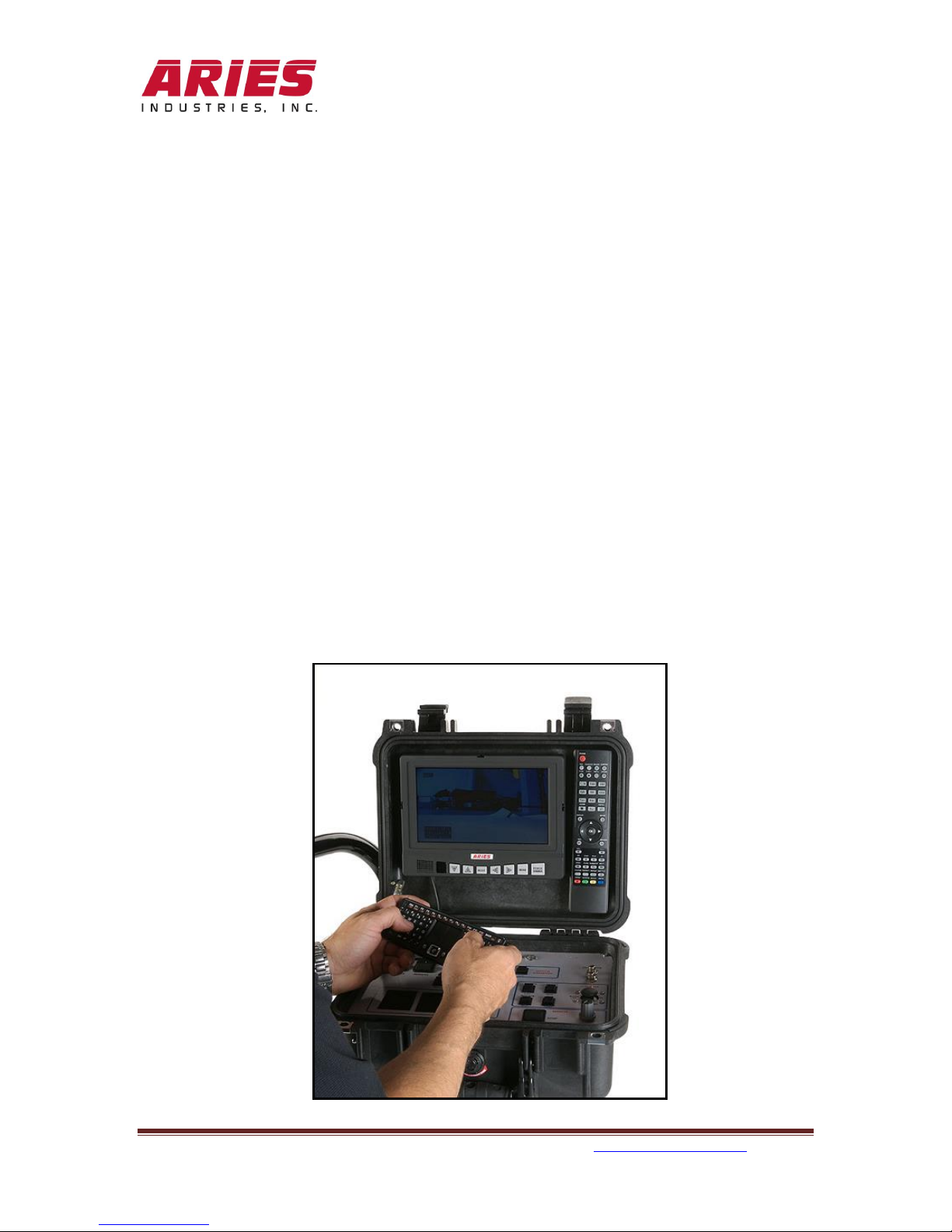
8. An IR sensor is located to the right of the USB Video Storage slot. It receives the
signals from the remote control to operate the DVR.
9. The DEPTH COUNTER switch will Zero out the footage display or Preset the
preconfigured depth setting. See pages 19 and 20 for further details.
10. The AUDIO and VIDEO OUTPUTS will allow for additional viewing and
recordings by plugging in another recording device or monitor (not supplied).
11. The CAMERA functions include:
a. LAMPS* –Low, Medium, and High settings. This will allow for more or less
lighting in depending on diameters necessary to illuminate. Lamp settings are
allowable in both side and down views.
*NOTE: The down view light can be enabled/ disabled by pressing down on
the joystick in the center position.
b. FOCUS –Far and Near. Is used depending on the object(s) needed to see with
more clarity. Focus is allowable in both the side and down views.
c. ROTATE –The rotate rocker switch allows for slow or fast camera side view
movement.
d. IRIS –Allows for more or less camera light sensitivity by adjusting the
electronic shutter settings. Either Open for more “light” or Close for less.
e. Cam Side - Press the joystick upward for Camera side viewing.
f. Cam Down –Press the joystick downward for camera down viewing.
g. Rotate Left* –Press the joystick left to start the camera rotation to the left.
h. Rotate Right* –Press the joystick right to start the camera rotation to the right.
*NOTE: If held in these positions for more than 3 seconds the rotation will
continue automatically. Press again to stop the rotation.
12. The WINCH section controls the speed and operation of the winch.
a. Up will retrieve the cable onto the drum.
b. Stop will hold the cable in place.
c. Down will allow the cable to spool out.
d. Speed will increase or decrease as the knob is turned clockwise or
counterclockwise.
13. The MIC (Microphone) is located in the center of the Control Unit and will
record all audio if the recording is started and the switch is in the Talk position.
Note: The audio is not available unless the DVR is powered ON and in the
CAMERA VIEW selection.

970215_C 0915 550 Elizabeth St., Waukesha, WI 53186 800-234-7205 www.ariesindustries.com Page 9
14. The Mute position will mute any audio.
15. The Keyboard USB port is fitted with the receiver for the wireless keyboard.
Removal will disable the keyboard function.
16. The wireless keyboard is attached to the control unit with Velcro® to prevent it
from movement during transport. See page 25 for details and functions of the
keyboard.

970215_C 0915 550 Elizabeth St., Waukesha, WI 53186 800-234-7205 www.ariesindustries.com Page 10
(Typical equipment connections and setup)

970215_C 0915 550 Elizabeth St., Waukesha, WI 53186 800-234-7205 www.ariesindustries.com Page 11
WC1200 Camera Details and Operation:
The camera is constructed of 300 series Stainless Steel. It measures 1-3/4
inches by 23-½ inches in length and weighs approximately 6 lbs. It has no
external moving components. The camera provides side viewing and down
viewing video images. Internally the camera is charged with Nitrogen to prevent
condensation. The side view camera will rotate 360° continuously in either
direction. Other features include side view focus, iris (shutter control) and light
intensities. The field of view is ~86° at 480TV lines of horizontal resolution.
Operational temperatures from 0° to 180°F (80°c max). The camera has
illumination capable of inspecting boreholes of 2 to 12 inches in diameter.

970215_C 0915 550 Elizabeth St., Waukesha, WI 53186 800-234-7205 www.ariesindustries.com Page 12
The down viewing camera provides a downhole view for inspection purposes.
The built-in LED lighting is selectable of Low, Med, and High intensities. An OFF
feature is also available when using an external light attachment. The down
viewing camera has operator controlled focus and iris (electronic shutter)
controls.

970215_C 0915 550 Elizabeth St., Waukesha, WI 53186 800-234-7205 www.ariesindustries.com Page 13
The rear of the camera is where the cablehead connector will attach. Once
screwed in, it will create a water tight connection. Ensure the pins are not
broken, missing, bent or corroded.
The screw at the end of the camera covers the Nitrogen fill/refill port. The
camera is charged with ~10psi of Nitrogen to help displace humidity. The
camera is factory filled and is not field serviceable.

970215_C 0915 550 Elizabeth St., Waukesha, WI 53186 800-234-7205 www.ariesindustries.com Page 14
Red Code LED:
Too Low Pressure Warning: Flashes very slow (about 2 seconds per flash) if
pressure is less than 3 PSI.

970215_C 0915 550 Elizabeth St., Waukesha, WI 53186 800-234-7205 www.ariesindustries.com Page 15
Wireless Mini Keyboard with Touchpad:
This keyboard contains a rechargeable lithium-ion battery. Do not operate this
device in extreme humidity, heat or cold environments for long periods of time.
Misuse will void the device’s warranty.
1. The 4 LED indicators from top to bottom are:
a. RF Communication indicator
b. Charging indicator/Battery capacity indicator
c. Touchpad DPI Adjustable (green/red)
d. Caps indicator

970215_C 0915 550 Elizabeth St., Waukesha, WI 53186 800-234-7205 www.ariesindustries.com Page 16
2. Locate the USB charging port and the on/off slide switch. The keyboard
features an auto sleep and auto wake mode. If there is a long period of
inactivity, the keyboard will automatically go into sleep mode. During the
sleep mode the user can wake the unit by pressing any key.
3. The unit is supplied with a USB-A to Mini-B cable. Connect one end of the
cable to a USB port in order to charge the battery. When the battery is
low, the low-voltage light will flash to warn the user. The unit will
automatically turn off if the battery has been depleted. Note: Fully
charge the unit before operating for the first time. This device can be
used when charging, but will extend the charging time.
4. The KEYBOARD USB port has the wireless 2.4 GHz receiver pre-
installed. When the keyboard is in the ON position it will automatically
establish a connection.

970215_C 0915 550 Elizabeth St., Waukesha, WI 53186 800-234-7205 www.ariesindustries.com Page 17
OVERLAY OPERATION:
Your Explorer unit may be factory configured for proper operation. The following
information will guide you through the various capabilities of the overlay.
The OVERLAY POWER switch must be in the ON (up) position. Neither the
CAMERA nor DVR switches need to be ON in order for the overlay to display
information.
Note: Upon power up the overlay will briefly display the following information.
“ARIES Industries TANDEM V.10.4”
This is the correct overlay version for the Explorer system.
Turn on the wireless keyboard. (Slide switch on the left side –up) The red LED
on the top left hand side of the keyboard will illuminate.

970215_C 0915 550 Elizabeth St., Waukesha, WI 53186 800-234-7205 www.ariesindustries.com Page 18
STATUS WINDOW
Pressing F2 will display the menu below.
Pressing the “Enter” key on the keyboard will take you to the next screen.
Pressing the “Escape” key on the keyboard will return you to the previous screen.

970215_C 0915 550 Elizabeth St., Waukesha, WI 53186 800-234-7205 www.ariesindustries.com Page 19
BOX 2and BOX 3are displayed. BOX 2is highlighted. Press Enter to display
the next screen.
BOX 2is the location of information directly below the footage. You have 2
options for information.
The Explorer system does not support INCLINOMETER (PRIMARY), and
PRESSURE functions.
Use this scroll key to maneuver up or down, right or left on the screens.
By scrolling down and selecting DATE with the ENTER key, the current date will
be displayed directly below the on-screen footage.
Selecting BLANK will not allow the date to be displayed onscreen.

970215_C 0915 550 Elizabeth St., Waukesha, WI 53186 800-234-7205 www.ariesindustries.com Page 20
DEPTH SETUP
Scroll down to the DEPTH SETUP. Press ENTER. Select DEPTH COUNTER.
The following sub menu will be displayed.
Scroll up or down and press Enter to access each sub menu.
This manual suits for next models
2
Table of contents
Other Aries Analytical Instrument manuals
Popular Analytical Instrument manuals by other brands

YOKOGAWA
YOKOGAWA EXAxtZR instruction manual

Powerfix
Powerfix PEKK 4.3 A1 Operating Instruction and Safety Manual

RS Technical Services
RS Technical Services DD LITE 2 Operation manual

SCA
SCA PLU 367464 instruction manual

Tektronix
Tektronix TDS7000 Series Online programmer manual

Bosch
Bosch GLM 50 C Professional Original instructions