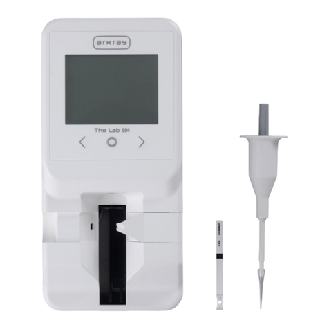
Arkray AUTION MAX AX-4030 User manual


AX-4030 3
AUTION MAX AX-4030 OPERATING MANUAL
Premise
This operating manual contains important information on the functions of the AUTION
MAX™ AX-4030.
This operating manual is issued by ARKRAY, Inc.
Read carefully prior to starting up the unit.
This instrument is IVD medical device.
This product conforms to European Directive 98/79/EC.

4AX-4030
AUTION MAX AX-4030 OPERATING MANUAL
Introduction
Read this operating manual thoroughly before using the instrument. This operating manual gives
an outline of the instrument and the proper procedures for operation and maintenance. Follow the
instructions in this operating manual in order not to impair the protection by the instrument.
Also, keep this operating manual in an easily accessible place near the instrument.
■ TAKE THE UTMOST CARE WHEN HANDLING URINE. This instrument
uses urine as sample and an ingredient of control solutions. Urine may be
contaminated by pathogenic microbes that can cause infectious diseases.
Improper handling of urine may cause infection to the user or other
individuals by pathogenic microbes.
■ This instrument is to be operated by qualified persons only. A qualified
person is one having adequate knowledge of clinical testing and the
disposal of infectious waste. Thoroughly read this operating manual before
use.
■ Never touch the aspirating nozzle, waste box, waste box tray, trap bottle,
drain bottle, drain tubes, transport tray, introduction tray, or other parts
where the sample may adhere with unprotected hands. During cleaning or
maintenance of these parts, wear protective gloves to prevent exposure to
pathogenic microbes.
■ Discard used samples, test strips, liquid waste, parts, and instrument in
accordance with local regulations for biohazardous waste.
© 2008 ARKRAY, Inc.
• It is strictly prohibited to copy any part of this operating manual without the expressed consent of
ARKRAY, Inc.
• The information in this operating manual is subject to change without notice.
• ARKRAY, Inc. has made every effort to prepare this operating manual as best possible. Should
you discover anything strange, incorrect or missing, contact your distributor.

AX-4030 5
AUTION MAX AX-4030 OPERATING MANUAL
Symbols
The following symbols are used in this operating manual and labels on this instrument to call your
attention to specific items.
For Your Safety
Follow the instructions given here to prevent exposure to pathogenic
microbes.
Follow the instructions given here to prevent injury and property damage.
For Optimal Performance
IMPORTANT: Follow the instructions given here to obtain accurate measurement results.
NOTE: Information useful for preventing damage to the instrument or parts, and other important
information you should keep in mind.
REFERENCE: Additional explanations that help you make the best use of the instrument, and
information on related functions.

6AX-4030
AUTION MAX AX-4030 OPERATING MANUAL
D
Caution Labels
This instrument has several caution labels on the areas that have potential dangers. Please learn
potential dangers warned by each label and observe the precautions described below.
■ Front
1. Sample aspirating section
The tip of the nozzle descends from here to aspirate samples. To avoid
injury, keep your hands away from here while the power is on. Also,
avoid touching the sample racks in the sampler while measurement is in
progress. Contact with moving sample racks may result in injury.
2. Front panel
The nozzle, washing bath, and other components inside this instrument
can be contaminated by urine samples. Do not touch these parts with
unprotected hands. Wear protective gloves to prevent exposure to
pathogenic microbes while cleaning these parts.
3. Trap bottle and tube
Do not touch liquid waste with unprotected hands to prevent exposure to
pathogenic microbes.
4. Maintenance section
The introduction tray, tubes and other components inside this section
can be contaminated by urine samples. Do not touch these parts with
unprotected hands. Wear protective gloves to prevent exposure to
pathogenic microbes while cleaning these parts.
5. Feeders
The test strip storage section of the feeder may move during measurement.
To avoid injury, do not touch inside the storage section when adding new
test strips to the feeder. Press the standby switch to turn off the power
before cleaning the test strip storage section.
3
5
4
1
2

AX-4030 7
AUTION MAX AX-4030 OPERATING MANUAL
■ Rear
1. Drain joint
Liquid waste is discharged from this joint to the drain bottle. Do not touch
liquid waste with unprotected hands because the drainage contains urine
samples. When cleaning the drain joint, tube and bottle, wear protective
gloves to prevent exposure to pathogenic microbes.
2. Washing solution joint
The washing solution in the washing solution bottle goes through this
joint. Use the specified washing solution.
3. Power input terminal
The supplied power cord is plugged in here. Use of other cords may cause
electric shock or fire. The fuse holders are also located here. Prepare fuses
of the specified capacity for replacement.
4. Waste box and waste box tray
Used test strips are collected in this box. When discarding the test strips,
wear protective gloves to prevent exposure to pathogenic microbes.
1
2
3
4

8AX-4030
AUTION MAX AX-4030 OPERATING MANUAL
E
■ Inside
1. Transport tray
The transport tray can be contaminated by urine samples. Do not touch
this tray with unprotected hands. Wear protective gloves to prevent
exposure to pathogenic microbes while cleaning these parts.
2. Introduction tray
The introduction tray can be contaminated by urine samples. Do not
touch this tray with unprotected hands. Wear protective gloves to prevent
exposure to pathogenic microbes while cleaning these parts.
3. Test strip storage section
Contact with the electrical circuits can damage the instrument. Do not
touch the electrical circuits.
1
2
1. Transport tray
2. Introduction tray
3

AX-4030 9
AUTION MAX AX-4030 OPERATING MANUAL
■ Drain Bottle
1. Drain Bottle
Liquid waste is collected in this bottle. When discarding liquid waste, wear
protective gloves to prevent exposure to pathogenic microbes.
■ Washing solution bottle
1. Washing solution bottle
Fill this bottle with the washing solution prepared as specified.
1
1

10 AX-4030
AUTION MAX AX-4030 OPERATING MANUAL
G
Table of Contents
Premise .......................................................................... 3
Introduction..................................................................... 4
Symbols.......................................................................... 5
Caution Labels................................................................ 6
Table of Contents ......................................................... 10
Chapter 1 Before Use
1.1 Outline of the AX-4030 ....................................... 1-2
1.1.1 What You Can Do with the AX-4030................ 1-2
1.1.2 Features ........................................................... 1-3
1.1.3 Specifications .................................................. 1-5
1.1.4 Measurement Principle .................................... 1-6
1.1.5 Rank Table..................................................... 1-11
1.2 Unpacking ......................................................... 1-13
1.2.1 Instrument ...................................................... 1-13
1.2.2 Sampler.......................................................... 1-13
1.2.3 Accessories.................................................... 1-14
1.2.4 Accessory Case ............................................. 1-15
1.3 Components ...................................................... 1-16
1.3.1 Front View ...................................................... 1-16
1.3.2 Rear View....................................................... 1-17
1.4 Installation......................................................... 1-18
1.4.1 Precautions in Instrument Installation ............ 1-18
1.4.2 Unlocking the Instrument ............................... 1-20
1.4.3 Attaching the Sampler.................................... 1-23
1.4.4 Installing the Washing Solution Bottle............ 1-26
1.4.5 Installing the Drain Bottle ............................... 1-28
1.4.6 Installing the Waste Box................................. 1-29
1.4.7 Connecting the Power Cord and
External Devices ............................................ 1-30
1.5 Starting Up ........................................................ 1-31
1.5.1 Turning On the Power for the First Time........ 1-31
1.5.2 Setting up the Printer and System Clock ....... 1-33
1.5.3 Turning Off the Power .................................... 1-34
1.6 Relocation ......................................................... 1-35
1.6.1 Precautions in Instrument Relocation ............ 1-35
1.6.2 Checking for Leftover Test Strips................... 1-35
1.6.3 Discharging the Washing Solution ................. 1-36
1.6.4 Unplugging the Power Cord ........................... 1-36
1.6.5 Disconnecting the Tubes,
Sensor Code, and Cables .............................. 1-37
1.6.6 Detaching the Sampler................................... 1-38
1.6.7 Relocating the Instrument .............................. 1-39
1.7 Basic Operations .............................................. 1-40
1.7.1 Components on the Operator Panel .............. 1-40
1.7.2 Screen Configuration ..................................... 1-41
1.7.3 Menu Operations and Examples.................... 1-42
Chapter 2 Measurement
2.1 Before Making Measurements........................... 2-2
2.1.1 Flowchart of Operational Procedure ................ 2-2
2.1.2 Measurement and Calibration .......................... 2-3
2.1.3 Measurement Terminology .............................. 2-4
2.1.4 Sample Containers and Sample Racks ........... 2-7
2.2 Measurement Precautions ................................. 2-9
2.2.1 Handling the Instrument ................................... 2-9
2.2.2 Handling Samples .......................................... 2-10
2.2.3 Handling Test Strips....................................... 2-11
2.3 Preparation for Measurement.......................... 2-12
2.3.1 Checking Wastes and Consumables ............. 2-12
2.3.2 Turning on the Power..................................... 2-14
2.3.3 Loading Test Strips into the Feeders ............. 2-16
2.3.4 Assigning the Type of Test Strips
to the Item Racks ........................................... 2-19
2.3.5 Preparing Samples......................................... 2-21
2.4 Measurement Operations ................................ 2-23
2.4.1 Normal Measurement:
Measuring Samples Continuously.................. 2-23
2.4.2 Port STAT Measurement:
Measuring a Higher Priority Sample .............. 2-27
2.4.3 Rack STAT Measurement:
Measuring Higher Priority Samples................ 2-31
2.5 S.G. Calibration................................................. 2-34
2.5.1 Preparing S.G. Standard Solutions ................ 2-34
2.5.2 Starting S.G. Calibration ................................ 2-36
2.6 Control Measurement....................................... 2-38
2.7 Check Measurement......................................... 2-43
2.8 Displayed and Printed Reports ....................... 2-49
2.8.1 Displayed Results Report............................... 2-49
2.8.2 Printed Results Report ................................... 2-50
2.8.3 Abnormal Results List .................................... 2-54
AX-4030 11
AUTION MAX AX-4030 OPERATING MANUAL
G
2.8.4 Error and Trouble List (Automatic Report) .... 2-54
2.8.5 Trouble List (Manual Report) ........................ 2-55
2.8.6 Check Measurement Result Report ............... 2-56
2.8.7 List of Current Parameter Settings................. 2-57
Chapter 3 Auxiliary Operations
3.1 Menu Configuration ............................................ 3-2
3.2 [Parameter settings] Menu ................................ 3-4
3.2.1 Assigning the Type of Test Strips
to the Item Racks ............................................. 3-4
3.2.2 Using a Different Results Format ..................... 3-4
3.2.3 Configuring the Measurement
Numbering Method........................................... 3-6
3.3 [Results] Menu .................................................... 3-8
3.3.1 Printing/Transmitting Results ........................... 3-8
3.3.2 Reviewing Results/Editing IDs ....................... 3-12
3.3.3 Deleting Results and Trouble Logs
from Memory .................................................. 3-15
3.4 [Initial settings] Menu ....................................... 3-17
3.4.1 Setting the System Clock ............................... 3-17
3.4.2 Enabling/Disabling the Built-in Printer............ 3-18
3.4.3 Enabling/Disabling the External Output ......... 3-20
3.4.4 Controlling the Beeper Volume ...................... 3-21
3.5 [Print] Menu ....................................................... 3-23
3.5.1 Printing a Trouble List .................................... 3-23
3.5.2 Printing the Abnormal Results List ................. 3-24
3.5.3 Printing the Current Parameter Settings ........ 3-25
3.6 [Maintenance] Menu ......................................... 3-27
3.6.1 Viewing Maintenance Information .................. 3-27
Chapter 4 Maintenance
4.1 Frequency of Maintenance ................................ 4-2
4.2 Daily Maintenance .............................................. 4-3
4.2.1 Cleaning the Waste Box................................... 4-3
4.2.2 Discarding Liquid Waste from
the Drain Bottle ................................................ 4-5
4.2.3 Cleaning the Feeders....................................... 4-6
4.2.4 Cleaning the Test Strip Stopper ....................... 4-8
4.2.5 Washing the Introduction Tray ....................... 4-12
4.3 Replacement of Consumables ........................ 4-15
4.3.1 Replacing the Washing Solution .................... 4-15
4.3.2 Replacing the Thermal Printer Paper............. 4-17
4.4 Regular Maintenance ....................................... 4-18
4.4.1 Washing the Air Filter..................................... 4-18
4.4.2 Washing the Transport Tray........................... 4-19
4.4.3 Cleaning the S.G. Cell.................................... 4-24
4.4.4 Cleaning the Washing Bath............................ 4-26
4.4.5 Replacing the Washing Solution Filter ........... 4-29
4.4.6 Replacing the Drain Pinch Valve Tubes......... 4-30
4.4.7 Replacing the White Plate.............................. 4-32
4.5 Before/After Long Periods of Disuse.............. 4-34
4.5.1 Preparing the Instrument Before
Long Periods of Disuse .................................. 4-34
4.5.2 Starting the Instrument Up
After Long Periods of Disuse ......................... 4-37
Chapter 5 Troubleshooting
5.1 When a Warning Occurs .................................... 5-2
5.1.1 From Warning Generation to Remedy ............. 5-2
5.1.2 Causes and Remedies..................................... 5-3
W001 – W003............................................. 5-3
W004 – W009............................................. 5-4
W010 – W011............................................. 5-5
5.2 When an Error Occurs ....................................... 5-6
5.2.1 From Error Generation to Remedy................... 5-6
5.2.2 Causes and Remedies..................................... 5-7
E101 – E104............................................... 5-7
E110 – E120............................................... 5-8
E130 – E140............................................... 5-9
5.3 When Trouble Occurs ...................................... 5-10
5.3.1 From Trouble Generation to Remedy ............ 5-10
5.3.2 Causes and Remedies................................... 5-11
T999, T201 – T203...................................5-11
T210 – T220 ............................................. 5-12
T221 – T222 ............................................. 5-13
T223 – T240 ............................................. 5-14
T241 – T261 ............................................. 5-15
T270 – T290 ............................................. 5-16

12 AX-4030
AUTION MAX AX-4030 OPERATING MANUAL
G
5.4 Measurement-Related Messages .................... 5-17
5.4.1 Results-Related Errors (Printed Results
Reports: on the lowest line)............................ 5-17
No sample ................................................ 5-17
Skipped..................................................... 5-17
Reflection light intensity drift..................... 5-17
Excess reflectivity ..................................... 5-18
Test strip out-of-position...........................5-18
Abnormal sampling................................... 5-18
5.4.2 S.G. Measurement-Related Errors
(Printed Results Report: S.G.) ...................... 5-19
UNDER..................................................... 5-19
OVER ....................................................... 5-19
---------....................................................... 5-19
CAL. ERR ................................................. 5-19
5.4.3 Turbidity Measurement-Related Errors
(Printed Results Report: TURB) .................... 5-20
CAL. ERR ................................................. 5-20
ERROR..................................................... 5-20
5.4.4 Messages on the Abnormal Results List........ 5-20
Barcode misread ...................................... 5-20
No sample ................................................ 5-20
Measurement error ................................... 5-21
Abnormal data .......................................... 5-21
Positive sample ........................................ 5-21
S.G. measurement error........................... 5-21
Turbidity measurement error .................... 5-21
5.5 If This Happens ................................................. 5-22
5.5.1 If the Instrument Does Not Start Up
(Replacing Fuses) ......................................... 5-22

AX-4030 1-1
AUTION MAX AX-4030 OPERATING MANUAL
G
Before Use
1.1 Outline of the AX-4030 .............................................1-2
1.1.1 What You Can Do with the AX-4030 ..........1-2
1.1.2 Features......................................................1-3
1.1.3 Specifications .............................................1-5
1.1.4 Measurement Principle ...............................1-6
1.1.5 Rank Table ...............................................1-11
1.2 Unpacking ...............................................................1-13
1.2.1 Instrument.................................................1-13
1.2.2 Sampler ....................................................1-13
1.2.3 Accessories ..............................................1-14
1.2.4 Accessory Case........................................1-15
1.3 Components............................................................1-16
1.3.1 Front View.................................................1-16
1.3.2 Rear View .................................................1-17
1.4 Installation...............................................................1-18
1.4.1 Precautions in Instrument Installation.......1-18
1.4.2 Unlocking the Instrument ..........................1-20
1.4.3 Attaching the Sampler ..............................1-23
1.4.4 Installing the Washing Solution Bottle ......1-26
1.4.5 Installing the Drain Bottle..........................1-28
1.4.6 Installing the Waste Box ...........................1-29
1.4.7 Connecting the Power Cord and
External Devices............................1-30
1.5 Starting Up ..............................................................1-31
1.5.1 Turning On the Power for the First Time ..1-31
1.5.2 Setting up the Printer and System Clock ..1-33
1.5.3 Turning Off the Power...............................1-34
1.6 Relocation ...............................................................1-35
1.6.1 Precautions in Instrument Relocation .......1-35
1.6.2 Checking for Leftover Test Strips .............1-35
1.6.3 Discharging the Washing Solution............1-36
1.6.4 Unplugging the Power Cord......................1-36
1.6.5 Disconnecting the Tubes,
Sensor Code, and Cables.........................1-37
1.6.6 Detaching the Sampler .............................1-38
1.6.7 Relocating the Instrument.........................1-39
1.7 Basic Operations....................................................1-40
1.7.1 Components on the Operator Panel .........1-40
1.7.2 Screen Configuration ................................1-41
1.7.3 Menu Operations and Examples ..............1-42
Chapter 1

1-2 AX-4030
AUTION MAX AX-4030 OPERATING MANUAL
B
Outline of the AX-40301.1
1.1.1 What You Can Do with the AX-4030
Measurement Items
The AX-4030 uses test strips to analyze urine samples fully automatically. Comprehensive
assessments can be made based on color-tone and turbidity measurements, abnormal coloration
detection, S.G. (specific gravity) measurement, as well as ten qualitative analyses of GLU
(glucose), PRO (protein), BIL (bilirubin), PH (pH), BLD (blood), URO (urobilinogen), KET
(ketones), NIT (nitrite) and LEU (leukocytes).
Measurement Method
AX-4030 performs the following measurements.
■ Normal measurement
Normal measurement continuously measures a number of samples loaded in the sample racks.
A sample rack can contain up to 10 samples. Place the sample racks with samples in the sampler
and press the start key. The instrument then automatically transports the sample racks, aspirates
the samples in order, and obtains the results. Up to 5 sample racks (50 samples) can be loaded
into the sampler for one-way transportation, and up to 10 sample racks (100 samples) for loop
transportation.
* The instrument is factory-set to the one-way transportation mode. If you prefer loop transportation to measure more
samples at a time, contact your distributor.
■ STAT measurement
STAT measurement is used to interrupt ongoing normal measurements and measure one or more
urgent samples. There are two types of STAT measurements:
Port STAT measurement: Measures a single sample loaded into the STAT port. If you have
a sample to test urgently, you can load the sample into the STAT
port to interrupt normal measurements in progress.
Rack STAT measurement: Interrupts normal measurements in progress to measure up to 7
samples loaded into the STAT and control rack.
■ Control measurement
The specified controls should be measured at regular intervals for the quality control of the
instrument. Use the STAT and control rack to load the controls. Up to 3 types (or 3 concentrations)
of controls can be used at a time.
■ Check measurement
If obtained measurement results seem inaccurate, perform a check measurement using the supplied
check strips to check if the instrument is working correctly.

AX-4030 1-3
AUTION MAX AX-4030 OPERATING MANUAL
1.1.2 Features
■ Easy to operate
Daily measurements are done in three easy steps: 1) load the test strips, 2) load the samples, and
3) press the start key. After pressing the start key, the instrument automatically performs the
entire series of operations to effectuate measurement: test strip picking, sample transport, sample
aspiration, test strip staining, measurement, and test strip disposal.
■ Test strip staining
After aspirating sample with a nozzle, the instrument stains each reagent pad on the test strip with
a small quantity of sample. Measurements can be performed as long as there is at least 2 mL of
sample in the sample tube.
■ Dual test strip feeders for multiple test strips
The instrument has two feeders, therefore two types of test strips can be loaded in the instrument
at all times. When using the supplied item racks, test strips can be automatically picked from
the feeder assigned to the item racks so as to expedite measurement. This reduces the hassles of
changing test strips in/out and makes measurement work more efficient.
■ Large color LCD
A large color LCD makes measurement conditions and menu settings easy to read and identify,
which facilitates operation. If a warning occurs such as test strips or solution running out, remedial
action is displayed in English so that the situation can be quickly corrected.
■ Thermal compensation function
The best temperature range for measurements is 20 - 25°C, but some measurement items may not
yield correct results if visually evaluated outside of this range. The thermal compensation feature of
this instrument has an advantage over human visual evaluation in that it minimizes errors caused by
temperature changes within a 10 - 30°C range to deliver correct measurement results.
■ General diagnostics support
Samples are measured according to color, turbidity and abnormal coloration detection. These
capabilities eliminate the need for visual evaluation and provide useful information for basing
evaluations on printed results.
Color-tone measurement
The instrument examines the color of the sample by measuring contrast and hue. It evaluates
samples against 23 colors (see page 1-9).
Turbidity measurement
The instrument measures turbidity and evaluates samples as “clear”, “turbid” or “dense
turbid”.

1-4 AX-4030
AUTION MAX AX-4030 OPERATING MANUAL
Abnormal coloration detection
The instrument automatically detects false positive reactions of reagent pads caused by drug-
administered urine and notifies you by adding a “!” to printed measurement results.
■ Memory capacity for measurement results of 2,500 samples
Measurement results for a total of 2,500 samples, between normal measurements and STAT
measurements, can be stored in memory. These results can be displayed, printed and sent to
an external device as necessary. As new data is recorded above 2,500 samples, the old data is
sequentially deleted. Up to 200 control measurements, 50 check measurements and 100 troubles
can be logged.
■ Management by barcode
Measurement results can be managed by ID using a barcode reader. If a barcode label is affixed
to the sample tube, the barcode is read during measurement and assigned to the measurement
results as an ID. A built-in barcode reader is included with the instrument as part of the standard
equipment, while a hand-held barcode reader is optionally available.
■ Two-way/one-way online communications
The instrument can be connected to an external device for two-way or one-way communications. It
can operate as a component in an online network configuration.

AX-4030 1-5
AUTION MAX AX-4030 OPERATING MANUAL
B
1.1.3 Specifications
Specifications
Product AUTION MAX AX-4030
Configuration Instrument, sampler, and accessories
Sample Urine
Reagent AUTION Sticks 9EB
Instrument specifications
Measurement items GLU (Glucose), PRO (Protein), BIL (Bilirubin), URO (Urobilinogen), PH (pH), BLD (Blood),
KET (Ketones), NIT (Nitrite), LEU (Leukocytes), S.G. (Specific gravity), turbidity,
and color tone
Measurement range Test strip: For rank table, see page 1-11.
S.G.: 1.000 to 1.050 (Resolution: 0.001)
Color tone: For color classification diagram, see page 1-9.
Turbidity: Three levels including “clear”, “turbid”, and “excessively turbid”
Measurement method Test strip: Dual-wavelength reflectance measurement (Single wavelength for BLD)
S.G.: Reflection refractometry
Color tone: Light-transmission measurement
Turbidity: Light-scattering measurement
Measurement wavelength 5 LED wavelengths (430, 500, 565, 635, 760 nm)
Sample supply Sampler
Test strip reaction About 60 seconds
Test strip storage Two test strip storage compartments, each of which can contain different test strips
Test strip storage capacity Max. 200 test strips × two storage compartments
Processing speed 225 samples/hour
Sample consumption 0.90 mL
Required sample volume Min. 2.0 mL
Sample container Use the sample tubes that comply with the standards illustrated in “Sample Containers” in
“2.1.4 Sample Containers and Sample Racks” on page 2-7.
Applicable racks ARKRAY racks
Sample loading capacity One-way transportation (default): Max. 50 samples, Loop transportation: Max. 100 samples
Warm-up time Max. 2 minutes
Display Large color liquid crystal display (320 × 240 dots)
Built-in printer 58-mm width thermal printer paper (24 digits)
Memory capacity Normal and STAT measurement: 2500 tests
Control measurement: 200 tests
Check measurement: 50 tests
Trouble list: 100 tests
External output 2 ports (One of these ports can be optionally used as an Ethernet port.)
Communication system RS-232C compliant (Switchable between one-way and two-way)
Transmission speed RS-232C: Selectable from 300, 600, 1200, 2400, 4800, 9600, and 19200 bps
Ethernet: 10BASE-T
Thermal compensation Supported
Operating environment Temperature: 10 - 30°C; Humidity: 20 - 80% RH (Non-condensing)
Measurement environment Temperature: 10 - 30°C; Humidity: 30 - 60% RH (Non-condensing)
Storage environment Temperature: 1 - 30°C; Humidity: 20 - 80% RH (Non-condensing)
Environment during transport Temperature: -13 - 43°C; Humidity: 20 - 80% RH (Non-condensing)
Dimensions 530 (W) × 530 (D) × 530 (H) mm
Weight Instrument: approx. 37 kg; Sampler: approx. 4 kg
Supply voltage (Instrument) 100 - 240 V AC (Max. power line fluctuation of ±10%), 50/60 Hz
Power input Max. 150 VA
Sound pressure level Less than 85 dB
Site location For indoor use only
Altitude 2000 m
Pollution degree 2
Over voltage category II
Expected life 5 years (According to company data)

1-6 AX-4030
AUTION MAX AX-4030 OPERATING MANUAL
B
1.1.4 Measurement Principle
This instrument measures purpose-specific test strips by dual-wavelength reflectance measurement
(single wavelength for BLD) and urine specific gravity (S.G.) by reflection refractometry.
This section explains the principles for measuring “test strips”, “specific gravity”, “color”, and
“turbidity”.
Test Strip Measurement
Test strips loaded in the feeder are sent one at a time to the tray inside the instrument and carried
to the sample staining position by the introduction arm. At the sample staining position, the
nozzle that aspirated the sample from the sample tube in the sampler stains each reagent pad (each
measurement item) of the test strip. Once stained, the test strip is transported to the optical block.
Within about 60 sec of staining, the test strip reacts and changes color, therefore its reflectivity is
measured in that moment. When measurement has been completed, the test strip is discarded in the
waste box.
The measurement unit irradiates the reagent pad with light of 2 wavelengths from a 5-wavelength
LED, the reflected light of which is picked up by a single detector.* Moreover, by measuring the
reflectivity of the color correction pad of the test strip, destabilizing factors such as the amount of
reflected light and colored samples are corrected.
* The irradiated wavelength combinations differ according to measurement item.
Wavelengths by measurement item
Measurement item GLU PRO BIL URO PH BLD KET NIT LEU
Measurement
wavelength (nm)
635 635 565 565 635 635 565 565 565
Reference
wavelength (nm)
760 760 760 760 760 – 760 760 760
Reflectivity is measured with the formula below.
R = (Tm • Cs) / (Ts • Cm)
R: Reflectivity
Tm: Amount of reflected light coming from reagent pad at measurement wavelength
Ts: Amount of reflected light coming from reagent pad at reference wavelength
Cm: Amount of reflected light coming from color correction pad at measurement
wavelength
Cs: Amount of reflected light coming from color correction pad at reference
wavelength
However, BLD is measured with only one wavelength and calculated with the formula below.
R = Tm / Cm

AX-4030 1-7
AUTION MAX AX-4030 OPERATING MANUAL
F
These reflectivities “R” are compared against calibration curves stored in the instrument and
output as measurement results. Also, temperature is corrected to eliminate changes caused by
environmental temperature.
Specific Gravity (S.G.) Measurement
Specific gravity of a urine sample is obtained by measuring the refraction of the sample using a
prism and subjecting results to a calculation formula (reflection refractometry). The light from an
LED passes through the prism and is reflected on the prism face contacting the sample. The light
reflected off the prism is collimated into a thin beam by passing through a slit and directed to a
detector (CCD image sensor). At this point, the refractive index at the interface between the prism
face and sample will change according to the specific gravity, therefore the position of the incident
light from the slit will change. The refractive index is obtained by detecting the position of the
incident light and, after correcting it for temperature effects, it is converted into a Brix value. The
specific gravity of the sample is then obtained using this Brix value and a conversion formula.
The Brix value is the sugar content of an aqueous solution measured at 20°C and represents the
strength of the solution as percentage by weight.
For example, the Brix value is 30% for a 30% sucrose solution (30 g of sucrose sugar and 70 g of
water in a 100 g solution).
Specific gravity is calculated as follows:
1. The specific gravity of the sample is calculated.
SGx´ = 1 + (4/900) *Brix value
(However, specific gravity is equal to 1,000 if the Brix value is below 0.)
2. Correction coefficients aand bare calculated from the low and high specific gravity values
obtained from S.G. calibration.
a = SGL– SGH
KL– KH
b = SGL– (a × KL)
Light source (LED) Flow cell Sample route Prism Slit
Specific gravimeter unit
CCD image sensor

1-8 AX-4030
AUTION MAX AX-4030 OPERATING MANUAL
A
3. The obtained specific gravity value of the sample is corrected using correction coefficients aand
b.
SGx = a × SGx´ + b
SGx: Sample’s specific gravity after calibration correction
SGx´: Sample’s specific gravity before calibration correction
SGH:Specific gravity reference of standard solution (high)
SGL:Specific gravity reference of standard solution (low)
KH:Specific gravity of standard solution (high)
KL:Specific gravity of standard solution (low)
Furthermore, high concentrations of glucose (GLU) and protein (PRO) will affect specific gravity.
Therefore, specific gravity is corrected using the concentrations of glucose and protein obtained
from test strip measurement.
SG = SGx – CGLU – CPRO
SG: Specific gravity after GLU and PRO correction
SGx: Specific gravity obtained from formula 3.
CGLU:Corrected GLU value
CPRO:Corrected PRO value
Correction values (Unit of concentration: mg/dL)
GLU concentration 0 10 30 50 70 100
Correction value 0.0000 0.0000 0.0001 0.0002 0.0003 0.0004
150 200 300 500 1000 OVER
0.0006 0.0008 0.0012 0.0020 0.0040 0.0040
PRO concentration 0 5 10 20 30 50 70
Correction value 0.0000 0.0000 0.0000 0.0001 0.0001 0.0002 0.0002
100 150 200 250 300 600 OVER
0.0003 0.0005 0.0006 0.0008 0.0009 0.0018 0.0018
Color-Tone Measurement
An internal turbidity/color measurement unit measures sample color using transmitted light.
470 nm/525 nm/635 nm
multiple wavelength LED
Cylindrical cell (i.d. 1.8 mm)
Photodiode (transmitted light)
Photodiode (Scattered light)

AX-4030 1-9
AUTION MAX AX-4030 OPERATING MANUAL
A
In color-tone measurement, red (635 nm), green
(525 nm) and blue (470 nm) lights are irradiated on
the sample in the cylindrical tube and the hue and
contrast of the sample are obtained from the amount
of transmitted light.
The color is evaluated against 23 standard colors
consisting of light, normal and dark shades of yellow,
orange, brown, red, violet, blue and green (21 total),
plus colorless and other.
Hue is obtained from the areas in the coordinate
system at right. Coordinates are calculated as follows:
1. XYZ stimulus is obtained.
X = ( (a × R) + (b × G) + (c × B) ) ÷ 1000
Y = ( (d × R) + (e × G) + (f × B) ) ÷ 1000
Z = ( (g × G) + (h × B) ) ÷ 1000
R: Transmission intensity of 635 nm light
G: Transmission intensity of 525 nm light
B: Transmission intensity of 470 nm light
ato h: Correction coefficients
2. The x and y color coordinates are obtained from formula 1.
x = X ÷ (X + Y + Z)
y = Y ÷ (X + Y + Z)
3. The density is obtained from formula 2.
Contrast and hue indications (23 colors)
COLORLESS
YELLOW LIGHT, normal and DARK
are indicated for each color.
Example: LIGHT YELLOW,
YELLOW, and
DARK YELLOW
ORANGE
BROWN
RED
VIOLET
BLUE
GREEN
OTHER
(x2+ y2)
y
x
YELLOW
GREEN
BLUE
COLORLESS
VIOLET
RED
BROWN
ORANGE
Color classification
Table of contents
Other Arkray Measuring Instrument manuals

Arkray
Arkray SPOTCHEM EZ SP-4430 User manual

Arkray
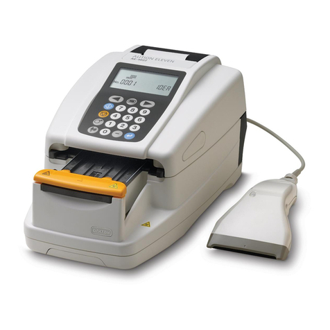
Arkray AUTION ELEVEN AE-4022 User manual

Arkray
Arkray Lab 004 User manual

Arkray
Arkray SPOTCHEM EL User manual

Arkray
Arkray AUTION ELEVEN AE-4022 User manual

Arkray
Arkray SPOTCHEM EZ Mounting instructions

Arkray
Arkray PocketChem UA User manual

Arkray
Arkray Lab 004 User manual
Popular Measuring Instrument manuals by other brands

Topcon
Topcon RL-H1Sa instruction manual

LaserLiner
LaserLiner EasyCross-Laser Green manual

HART
HART Proline Promass P 300 operating instructions

Banner
Banner SureCross Series manual

Aquaread
Aquaread AquaTelemetry instruction manual

PCB Piezotronics
PCB Piezotronics IMI Sensors TO625B01 Installation and operating manual