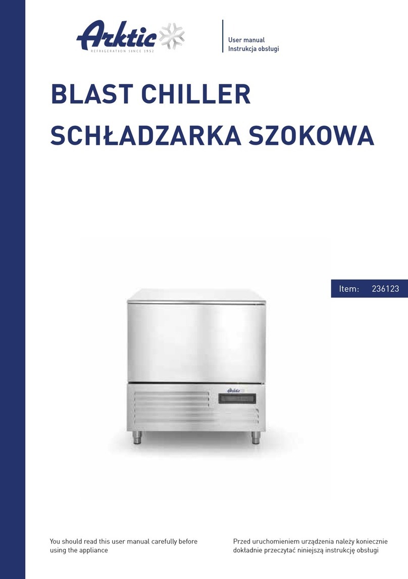
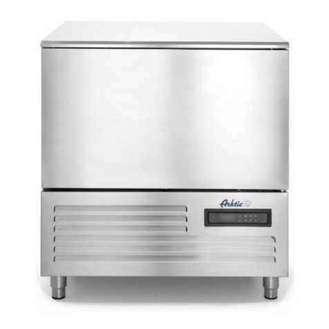
Arktic 236123 User manual

You should read this user manual carefully before
using the appliance
Przed uruchomieniem urządzenia należy koniecznie
dokładnie przeczytać niniejszą instrukcję obsługi
User manual
Instrukcja obsługi
Item: 236123
BLAST CHILLER
SCHŁADZARKO
ZAMRAŻARKA SZOKOWA

Keep this manual with the appliance.
Zachowaj instrukcję urządzenia.
For indoor use only.
Do użytku wewnątrz pomieszczeń.
2
EN

Dear Customer,
Thank you for purchasing this Arktic appliance. Before using the appliance for the first time, please read
this manual carefully, paying particular attention to the safety regulations outlined below.
1. IMPORTANT SAFETY INSTRUCTIONS
• This appliance is intended for commercial use only and must not be used for household use.
• The appliance must only be used for the purpose for which it was intended and designed. The manufac-
turer is not liable for any damage caused by incorrect operation and improper use.
• Keep the appliance and electrical plug away from water and any other liquids. In the event that the appli-
ance should fall into water, immediately remove plug from the socket and do not use until the appliance
has been checked by a certified technician. Failure to follow these instructions could cause a risk to lives.
• Never attempt to open the casing of the appliance yourself.
• Do not insert any objects in the casing of the appliance.
• Do not touch the plug with wet or damp hands.
• Danger of electric shock! Do not attempt to repair the appliance yourself. In case of malfunctions, repairs
are to be conducted by qualified personnel only.
• Never use a damaged appliance! Disconnect the appliance from the electrical outlet and contact the
retailer if it is damaged.
• Warning! Do not immerse the electrical parts of the appliance in water or other liquids. Never hold the
appliance under running water.
• Regularly check the power plug and cord for any damage. If the power plug or power cord is damaged, it
must be replaced by a service agent or similarly qualified persons in order to avoid danger or injury.
• Make sure the cord does not come in contact with sharp or hot objects and keep it away from open fire.
To pull the plug out of the socket, always pull on the plug and not on the cord.
• Ensure that the cord (or extension cord) is positioned so that it will not cause a trip hazard.
• Always keep an eye on the appliance when in use.
• Warning! As long as the plug is in the socket the appliance is connected to the power source.
• Turn off the appliance before pulling the plug out of the socket.
• Never carry the appliance by the cord.
• Do not use any extra devices that are not supplied along with the appliance.
• Only connect the appliance to an electrical outlet with the voltage and frequency mentioned on the appli-
ance label.
• Connect the power plug to an easily accessible electrical outlet so that in case of emergency the applian-
ce can be unplugged immediately. To completely switch off the appliance pull the power plug out of the
electrical outlet.
• Always turn the appliance off before disconnecting the plug.
• Never use accessories other than those recommended by the manufacturer. Failure to do so could pose
a safety risk to the user and could damage the appliance. Only use original parts and accessories.
• This appliance is not intended for use by persons (including children) with reduced physical, sensory or
mental capabilities, or lack of experience and knowledge.
• This appliance must not be used by children under any circumstances.
• Keep the appliance and its cord out of reach of children.
• Always disconnect the appliance from the mains if it is left unattended or is not in use, and before as-
sembly, disassembly or cleaning.
• Never leave the appliance unattended during use.
3
EN
2. SPECIAL SAFETY REGULATIONS
• This appliance is designed for short-time storage of cake for display to customer under low temperature. Do not
store any other materials in the appliance. Do not place any dangerous products, such as fuel, alcohol, paint,
flammable or explosives, etc. inside or near the appliance. No medicine is allowed to keep inside the appliance.
• Products put in the appliance must be already pre-cooled. Otherwise, moisture evaporating while cooling food
products can condensate inside the cooling compartment, which is natural and does not indicate any malfuncti-
on of the appliance.
• This appliance must be installed, commissioned and services by a qualified or trained person. And this applian-
ce is intended to be used by trained or qualified personnel such as kitchen or bar staff.
• WARNING: Do not use mechanical devices or other means to accelerate the defrosting process, other than
those recommended by the manufacturer.
• WARNING: Do not damage the refrigerant circuit.
Caution! Risk of fire! The refrigerant used is in appliances. It is a highly flammable refrigerant.
• WARNING: Keep all ventilation openings in the appliance enclosure clear of obstruction. Provide sufficient
ventilation in the surrounding structure when building-in. Never block the air flow suction and air outlet in order
to keep air circulation.
• WARNING: Do not use electrical appliances inside the food storage compartments of the appliance, unless they
are of the type recommended by the manufacturer.
• Place the appliance on a clean, stable, dry, level surface only.
• Keep the appliance away from any hot surfaces and open flames. Protect the appliance against heat, dust, direct
sunlight, moisture, dripping and splashing water.
• Allow at least 50 cm surrounding spacing for ventilation purpose during use.
• Do not use hard utensils to hit the glass surface. Do not use water jet, flush directly with water or steam cleaner
as the parts will get wet and electric shock might be resulted.
• Do not place articles on top of the appliance. Do not place objects with open sources of fire (e.g. candles) on top
or beside the appliance. Do not place objects filled with water (e.g. vases) on or near the appliance.
• Never cover the appliance during use. This may cause a fire hazard.
• Do not wash the appliance with water. Washing can cause leakages and increase the risk of electric shock.
• Do not make any additional openings on the appliance. Do not install any gadgets in the appliance.
• Do not overload the shelves inside to avoid damage. Max. loading of each shelf is about 40kg. Place the food
evenly on each shelf.
• Do not attempt to climb up to the top of the appliance.
3. SAFETY TIPS
CONSULT LOCAL AND NATIONAL STANDARDS TO COMPLY WITH THE FOLLOWING:
• Health and Safety at Work Legislation
• Fire Precautions
• IEE Wiring Regulations
• Building Regulations
• DO NOT use the appliance outside.
• DO NOT attempt to service the item yourself.
min. height 15mm :
4
EN

• DO NOT use damaged appliances. If you are in any doubt, consult service agent.
• DO NOT use electrical appliances inside the appliance (e.g. heaters, ice-cream makers etc.), unless they are
of the type recommended by the manufacturer.
• DO NOT use mechanical devices or other means to accelerate the defrosting process, other than those
recommended by the manufacturer.
• DO NOT stand or support yourself on the base, drawers or doors.
• DO NOT allow oil or fat to come into contact with the plastic components or door seal. Clean immediately if
contact occurs.
• This unit can be used by children aged above 8 years and persons with reduced physical, sensory or mental
capabilities or lacking of experience and knowledge who have been given supervision or using instruction of
the device and understand the resulting risks (for European market).
• Do not let children play with the appliance.
• Cleaning and user maintenance must not be carried out by children without supervision.
• DO NOT place combustible, explosive or volatile articles, corrosive acids or alkalis or liquids in the appliance.
• DO NOT use this appliance to store medical supplies.
• DO NOT use jet/pressure washers to clean the appliance.
• DO NOT allow children to play with the packaging, and dispose plastic bags safely.
• Bottles that contain a high percentage of alcohol must be sealed and placed vertically in the refrigerator.
• Always carry, store and handle the appliance in a upright orientation and move by holding the base of the
appliance.
• Always switch off and disconnect the power supply to the unit before cleaning.
• If the supply cord is damaged, it must be replaced by the manufacturer, its service agent or similarly qualified
persons in order to avoid a hazard.
• This appliance is not intended for use by persons (including children) with reduced physical, sensory or men-
tal capabilities, or lack of experience and knowledge, unless they have been given supervision or instruction
concerning use of the appliance by a person responsible for their safety (for market beyond European).
• Children should be supervised to ensure that they do not play with the appliance.
• For indoor use only. Not suitable for installation in an area where a water jet could be used. Shall not be
cleaned by a water jet.
• To guarantee safe operation, ensure that the appliance is set up and connected as described in the instructi-
on manual.
• Any repairs and work on the appliance should only be carried out by the customer service department/ quali-
fied technician.
• The key to the electrical cabinet should be kept out of the reach of children and users.
• Do not store explosive substances such as aerosol cans with a flammable propellant in this appliance.
4. INTENDED USE
Only use this appliance to blast chilling/freezing
food for commercial purposes.
• Any other use may lead to damage to the appli-
ance, other user property, or personal injury.
• No liability will be accepted for damage result-
ing from improper use or non-compliance
with this manual.
• Operating the appliance for any other purpose
means misuse of the appliance.
5
EN

5. LOCATION AND INSTALLATION
• Remove the appliance from the packaging. Make sure that all protective plastic film and coatings are tho-
roughly removed from all surfaces. To prevent injury or damage to the unit, we recommend that the appliance
should be unpacked and set up by two people.
• The climatic class can be found on the rating plate. It specifies the ambient temperatures at which the appli-
ance may be operated. The rating plate can be found behind the appliance.
Climate Class Max. Ambient Temperature Relative Humidity
325 60%
430 55%
540 40%
• Maintain a distance of 10 cm between the appliance and walls or other objects for ventilation. Increase this
distance if the appliance is near an a heat source.
• The appliance should be placed on a solid flat and stable floor to reduce noise and vibration. Level the appli-
ance by adjusting the feet.
• Avoid locating the unit in direct sunlight or near heat sources such as ovens or radiators.
• Please make sure the appliance is properly ventilated.
• Check that the power supply and voltage used comply with the details on the rating plate. The plug must be
accessible after installation.
• Correctly connect and disconnect the plug. When inserting ensure the plug is fully engaged. While unplugging
hold the body of the plug. Never pull the supply cord directly.
• Is advisable to install a bipolar switch with a NC contact (Normal Close) for the wire section at least 3 mm.
between socket and the appliance. This switch is mandatory when the load exceeds 1000 watts or when the
blast chiller is connected directly without plug. The thermal-braker switch must be placed near the blast
chiller so that it can be clearly visible by the technician in case of maintenance.
• Blast chiller is equipped with a built-in refrigeration engine, is necessary to avoid obstruct the air circulation
of the unit in correspondence at front grille, in this way it will allow a correct air exchange. Avoid depositing
products or other materials on the perimeter of the blast chiller. Remember that a rise of ambient tempera-
ture or insufficient air to the condenser of the refrigeration unit, reduce the performance of the blast chiller
with possible deterioration of the products and with more energy consumption.
• If the unit is to be shut down for long period, switch it off and disconnect the plug from socket outlet. Clean
the appliance and leave the door open to prevent odour.
• Important! For your personal safety, this appliance must be properly grounded (earthed). This appliance is
equipped with a cord having a grounding wire with a grounding plug. The plug must be inserted into an outlet
that is properly grounded and installed. Consult a qualified electrician or service centre if you do not comple-
tely understand the grounding instructions. If doubt exits whether the appliance is properly grounded, have a
qualified electrician check the circuit to make sure the outlet is properly grounded.
6
EN

• Location and Installation
• If the cable does not reach the nearest socket, either rearrange your store layout or ask a qualified electrician
to fix a new socket.
• If power is cut off, wait for at least 3 minutes before restarting the appliance to avoid damaging the compres-
sor.
Note: If the unit has not been stored or moved in
an upright position, let it stand upright for approxi-
mately 12 hours before operation.
Note: Before using the appliance for the first time,
clean the shelves and interior with soapy water.
6. OPERATION
ATTENTION
• This is a plug-in unit; once the blast chiller will be connetct to supply the item is in “Stand-by” mode; on the
display the icon is on.
• For switch ON the unit hold START/STOP key for 1 s. The items will display the inner room
chamber temperature.
• Every time the item back to “Stand-by” mode and the end user switch ON again the blast chiller will restart
from the latest operation recorded.
• At the end of the blast chilling cycle, the item switch in automatic to storage mode at a temperature from 0°C
to +2°c.
• At the end of the blast freezing cycle, the item switch in automatic to storage mode at a temperature from
-20°C to -18°C.
• To comply with the time required by law, while a blast chilling/freezing cycle is in progress, it is strongly rec-
comended don’t open the door of the blast chiller.
Temperature Setting and Control
Blast Chilling cycle Start/Stop cycle; Stand-by mode
Blast Freezing cycle Arrow DOWN
HARD/SOFT cycle Arrow UP; Defrost cycle
7
EN

If switch ON a Defrost cycle is in progress (The display show “def”)
If switch ON a Chilling cycle is in progress; if flashing cycle has bee selected
If switch ON a Freezing cycle is in progress; if flashing cycle has bee selected
If switch ON a HARD blast mode Chilling/Freezing cycle is in progress; if flashing HARD mode has
bee selected
If switch ON a temperature-controlled cycle is in progress; if flashing cycle has bee selected
(Temperature is detected by Needle probe Pb2)
If switch ON blast chiller is in “Stand-by” mode
If switch ON a time-controlled cycle is in progress; if flashing cycle has bee selected
(Temperature is detected by Chamber probe Pb1)
If switch ON a “Storage” cycle is in progress (Temperature is detected by Chamber probe Pb1)
If switch ON a “Pre-cooling” cycle is in progress; if flashing temperature is not reach yet (Temperatu-
re is detected by Chamber probe Pb1)
1. Switching the device On/Stand-by.
• Hold the START/STOP key for 1 s: the led icon will switch ON/OFF.
• From “Stand-by” mode to ON, hold the START/STOP key for 1 s: the led icon will switch OFF and
the display will show the chamber temperature “Pb1”
2. How to display Chamber temperature as per probe Pb1.
• Make sure that no cycles are in progress and/or any procedures has been selected
• Hold the Down key for 1 s: the display will show the first label available (rCH).
• Press and release the Up or Down key to select “Pb1”.
• Press and release the Chilling cycle key: the display will show the chamber temperature (Pb1).
• To exit procedure: N.3 possibility
1. Press and release two times the Chilling cycle key, the display will show after the first time the label
“Pb1” and after the second one the value of chamber temperature.
2. Press and release one times the Chilling cycle key, the display will show the label “Pb1” and do not
operate for 60 s. The display will show chamber temperature.
8
EN

3. Do not operate for 15 s: the display will show the value of chamber temperature or “timing cycle left”
depending on which cycle procedure (temperature-controlled or timing) is in progress.
3. How to display Needle probe temperature Pb2.
• Make sure that no cycles are in progress and/or any procedures has been selected
• Hold the Down key for 1 s: the display will show the first label available (rCH).
• Press and release the Up or Down key to select “Pb2”.
• Press and release the Chilling cycle key: the display will show the temperature detected by needle probe
(Pb2).
• To exit procedure: N.3 possibility
1. Press and release two times the Chilling cycle key, the display will show after the first time the label
“Pb2” and after the second one the value of needle probe temperature.
2. Press and release one times the Chilling cycle key, the display will show the label “Pb2” and do not
operate for 60 s. The display will show the needle probe temperature.
3. Do not operate for 15 s: the display will show the value of needle probe temperature.
Note: If the needle probe is not enabled (Parameter P3=0) the “Pb2“ label will not be displayed.
4. How to activate Defrosting cycle.
• Hold the UP key for 4 s: Defrost LED icon will switch on and diplay will show “def”.
• To exit procedure: switch OFF the unit or choose a cycle (Temperated controlled or timing)
5. How to start the Pre-cooling cycle.
Every operating cycle can be preceded by a pre-cooling:
• Hold the Chilling cycle key for 1 s: Pre-cooling led icon will start flashing. The cycle will run until reaching the
chamber pre-cooling set temperature (+1°C)
• Pre-cooling led icon will switch ON permanently and the buzzer is activated for 1 s
• Hold the Chilling cycle key for 1 s or start an operating cycle to stop pre-cooling cycle
Note: Parameter r12 establishes the working set-point during pre-cooling cycle
BLAST CHILLING AND FREEZING FUNCTIONALITY
Blast Chilling and Freezing cycle have two main working option: controlled by temperature or by time:
If operator chooses TEMPERATURE cycle option,
temperature will be detected by needle probe
“Pb2” and cycle will end once needle probe reach-
es the pre-setting temperature according to value
of parameter +3°C for chilling and -18°C for freez-
ing. After time cycle ends the device will switch
automatically to “storage mode” that will keep the
stored food at a pre-setting temperature: chilling
+2°C; freezing -20°C for a pre-setting duration
time according to a parameter value of 60 Min.
During the temperature cycle the display will show
always needle probe temperature “Pb2”. Once
storage cycle starts the display will show chamber
temperature “Pb1”.
Note: End user can modify the pre-setting end
needle temperature:
Press and release the UP or DOWN key again to
modify the time value: the display will flash. Do not
operate for 4 s: the display will stop flashing.
9
EN

If operator chooses TIME cycle option, temperature
will be detected by chamber probe “Pb1” and ther-
mostat display will show pre-setting time cycle of
120 Min. for chilling and 240 Min. for freezing. Once
chamber temperature reaches a pre-set value of
+3°C for chilling and -18°C for freezing the com-
pressor will stop. Cycle will end once the pre-set-
ting duration cycle time will reach 0 min.
After ending a time cycle the device will enter in a
“storage mode” that will keep the stored food at
pre- setting temperature according to the value
of parameter: chilling +2°C; freezing -20°C for a
pre-setting duration time according to a parameter
value of 60 Min. During the time cycle the display
will show time left to finish the cycle. Once storage
cycle starts the display will show chamber temper-
ature “Pb1”.
Note: End user can modify the residual time as
follow:
Press and release the UP or DOWN key again to
modify the time value: the display will flash. Do not
operate for 4 s: the display will stop flashing.
POSSIBLE OPERATION CYCLES:
• SOFT CHILLING CYCLE
• HARD CHILLING CYCLE
• SOFT FREEZING CYCLE
• HARD FREEZING CYCLE
Note: All above cycles can be active by temperature or by time
• To select “Temperature cycle” press and release
one time Blast Chilling key or Blast Freezing key.
Needle probeled icon will start flashing. (in the Blast
freezing cycle also the HARD led will start flashing)
• To select “Time cycle” press twice Blast Chilling
key or Blast Freezing key. Time led icon will
start flashing
• To stop the Temperature or Time cycle: Hold the
START/STOP key.
SOFT CHILLING CYCLE
Operate as follows to start the Temperature soft chilling cycle:
The temperature-controlled Soft Blast Chilling cycle is split in the following 2 phases:
• Blast Chilling Soft phase
• Storage
SOFT cycle is used when the end user wants a
smooth blast chilling process (Chamber tempera-
ture will never go down to a negative temperature);
during the first phase the setting point of chamber
temperature is 0.0°C (r7 parameter value). Once
the needle probe reaches temperature of +3°C
(r3 parameter value) the SOFT BLAST CHILLING
PHASE stops
1. Press and release one time Blast Chiling key to
select the cycle with temperature-control: the Chill
led icon and Needle probe led icon will start flash-
ing.
2. The display will show the pre-set blast chilling
temperature.
10
EN

3. Press and release START/STOP key to start tem-
perature Chilling cycle: the Chill led icon and the
Needle probe led icon will switch ON permanently.
4. Once the needle probe temperature reaches the
pre-setting point, a visual and acustic alarm will
notify the ending temperature cycle, the unit will
start a storage cycle and led icon will switch ON;
needle probe led icon will switch OFF.
Note: During the storage cycle the display will show chamber temperature (Pb1).
HARD CHILLING CYCLE
Operate as follows to start the Temperature hard chilling cycle:
The temperature-controlled Hard Blast Chilling cycle is split in the following 3 phases:
• Blast Chilling Hard phase
• Blast chilling Soft phase
• Storage
HARD cycle is used when the end user wants a
fast blast chilling process (Chamber temperature
will keep always a negative temperature); during
the first phase the setting point of chamber tem-
perature will be -20°C (r9 parameter value). Once
the Needle probe reaches temperature of +10°C
(r13 parameter value) the HARD BLAST CHILLING
PHASE stops and a SOFT blast chilling cycle starts.
Note: If the SOFT phase already start the led icon HARD still remain ON until the needle probe reaches the
temperature of +3°C (r3 parameter value)
1. Press and release one time Blast Chiling key to
select the cycle with temperature-control: the Chill
led icon and Needle probe led icon will start flash-
ing.
2. Press and release HARD/SOFT key: the led
HARD icon will start flashing.
3. The display will show the pre-set blast chilling
temperature.
4. Press and release one time START/STOP key to
start temperature HARD Chilling cycle: the Chill
Needle probe led icon and HARD led icon will
switch ON permanently.
5. Once the needle probe temperature reaches the
pre-setting point, a visual and acustic alarm will
notify the ending temperature cycle, the unit will
start a storage cycle and led icon will switch ON;
the needle probe and led HARD icon will switch
OFF.
Note: During the storage cycle the display will show chamber temperature (Pb1)
SOFT FREEZING CYCLE
Operate as follows to start the Temperature soft freezing cycle:
The temperature-controlled Soft Freezing cycle is split in the following 3 phases:
• Blast Freezing Soft phase
• Blast Freezing
• Storage
11
EN

SOFT cycle is used when the end user wants a
smooth freezing process (Chamber temperature
will never go down to a negative temperature). Once
the needle probe reaches temperature of +3°C
(r3 parameter value) the SOFT BLAST FREEZING
PHASE stops and a Blast freezing cycle starts until
the needle probe reaches temperature of -18°C (r4
parameter value)
1. Press and release one time Blast Freezing
key to select the cycle with temperature-control:
the Chill, Freeze, needle probe and HARD led icons
will start flashing.
2. The display will show the pre-set blast freezing
temperature.
3. Press and release HARD/SOFT key: the led
HARD icon will switch OFF.
4. Press and release START/STOP key to start tem-
perature soft blast freezing cycle: the Chill ,
Freeze and the Needle probe led icons will switch
ON permanently.
5. Once the needle probe temperature reaches the
pre-setting point, a visual and acustic alarm will
notify the ending temperature cycle, the unit will
start a storage cycle and led icon will switch ON;
needle probe led icon will switch OFF.
Note: During the storage cycle the display will show chamber temperature (Pb1).
HARD FREEZING CYCLE
Operate as follows to start the Temperature hard freezing cycle:
The temperature-controlled hard Freezing cycle is split in the following 3 phases:
• Blast chilling Hard phase
• Blast Freezing
• Storage
HARD cycle is used when the end user wants a fast
blast freezing process (Chamber temperature will
reach a temperature of -20°C (r9 parameter val-
ue). Once the needle probe reaches a temperature
of +3°C (r3 parameter value) the HARD BLAST
FREEZING PHASE stops and Blast freezing cycle
starts. Note: If the standard blast freezing phase
already start the led icon HARD will remain switch
ON until the needle probe reaches the temperature
of -18°C (r4 parameter value)
1. Press and release one time Blast Freezing
key to select the cycle with temperature-control:
the Chill , Freeze , Needle probe and HARD led
icons will start flashing.
2. The display will show the pre-set blast freezing
temperature
3. Press and release START/STOP key in to start
temperature hard blast freezing cycle: the Chill
,Freeze, needle probe and HARD led icons will
switch ON permanently.
4. Once the needle probe temperature reaches the
pre-setting point, a visual and acustic alarm will
notify the ending temperature cycle, the unit will
start a storage cycle and led icon will switch ON;
the needle probe and HARD led icon will switch
OFF.
Note: During the storage cycle the display will show chamber temperature (Pb1).
12
EN

THE DISPLAY
The display is OFF during the “OFF” status and during the “Stand-by” status.
The display shows the chamber temperature during the “ON” status.
The blast chiller will operate as follows during the “run” status:
• If a temperature-controlled blast chilling or blast freezing operation is in progress, the display will show the
temperature detected by the needle probe (Pb2).
• If a time-controlled blast chilling or blast freezing operation is in progress, the display will show the resid-
ual time of the cycle.
• If storage mode is in progress, the display will show the chamber temperature (Pb1).
The blast chiller is suitable for a fast dropping food product temperature (see the table with the temperatures
in relation to the product to freeze).
Do not put directly in the blast chiller food just taken out from the oven, wait few minutes before placing the
product inside the chamber and start the cycle.
Please note that the time to reduce the product temperature depends on several factors such as:
• The shape, the type, and the thickness of the ma-
terial in which the food is storaged
• Where the food is storaged is covered by lid or not.
• The physical characteristics of the food: density,
water content and fat content.
• The food temperature conditions before “blast
chilling/freezing”.
The time setting for blast chilling cycle needs to be
set according to the kind and/or weight of the food.
SELECTION MODE OF THE BLAST CYCLE (Positive or Negative temperature)
The following modes of blast chilling cycle can be selected:
• By time: If end user knows the exact time of food
blast chilling/freezing. When the cycle finishes
the appliance will switch automatically to storage
mode.
• By temperature: with needle sensor probe to be
inserted in the food core; set the temperature of
the food for blast chilling/freezing. The probe de-
tects the set temperature, after 1 acoustic signal
the blast chiller will switch to storage mode (see
needle probe sensor position chapter).
Blast chilling Cycle Cycle speed Kynd of food Load Cycle at food core
POSITIVE Full speed For all dense foods
and large sizes Max 4 Kg for tray +3°C MAX 90Min.
NEGATIVE Full speed For all dense foods
and large sizes 3 Kg Until to -18°C (240
minutes)
Reduced speed
Delicate products,
vegetables, creams,
spoon desserts,
small size products
13
EN

TEMPERATURE MEASUREMENT AT PRODUCT COR
When the product thickness allows, use always the temperature nee-
dle probe in order to know the exact temperature reached at the prod-
uct core. It is suggested to not interrupt the blast chilling cycle before
it has reached the temperature of +3 °c, in positive cycle and -18°C for
the negative cycle.
7. HOW TO USE
7.1. PLACING TRAYS AND CONTAINERS IN THE REFRIGERANT’S/FREEZER’S CHAMBER
Never stack food items on top of each other. Divide them evenly on the tray or GN container.
Keep vertical space between trays and/or GN containers
In order to ensure optimum circulation of hot air in the refrigerant’s/freezer’s chamber, a minimum verti-
cal distance of 40 mm between the trays or GN containers is required.
Positioning of trays and/or GN containers in the refrigerant’s/freezer’s chamber
To ensure optimum cold air circulation:
• Don’t position the tray or GN container against the fan
• Position them evenly and in the middle in the oven chamber
14
EN

STORAGED OF FOOD AFTER BLAST CHILLING CYCLE
The blast chilling/freezing food can be stored in the
refrigerator and keep the organoleptic qualities up
to 5 days from the blast chilling cycle. It is impor-
tant to respect the “cold chain”, keeping a constant
temperature between 0°C ÷ 4°C, depending on the
food. Using the vacuum technique, the storage
time can be increased up to about 15 days.
STORAGED OF FOOD AFTER BLAST FREEZING CYCLE
The frozen food can be stored in the refrigerator
maintaining the organoleptic qualities for several
months from the blast freezing cycle.
Food after a blast freezing cycle can be safely
stored for a period of 3 to 18 months, depending on
the kind of food. It is important to respect a storage
temperature equal or less than -20°C.
WARNING
Do not leave the cooked food at ambient temperature for long time before starting
blast chilling/freezing cycle.
Avoid moisture leakage, there is a risk to lose the preserved properties of the food.
Food after blast chilling/freezing must be protected by a food film (better if vacuum-packed) with a label in-
dicating the next information:
• Content
• Preparation day
• Expiration date
WARNING
Food already defrosted can not be frozen again
15
EN

BLAST CHILLING TIMES
Food Tray Max load Max load Chilling Times Cycle
FIRST COURSES
Béchamel GN1/1 h 60 6 L 4 cm 70 minutes POSITIVE
Meat broth GN 1/1 h 110 7 L 6-7 cm 90 minutes POSITIVE
Oven pasta GN 1/1 h 40 4 Kg 3-4 cm 40 minutes POSITIVE
Vegetables broth GN1/1 h 100 5 L 5 cm 90 minutes POSITIVE
Ragù and tomato GN1/1 h 60 5 Kg 5 cm 90 minutes POSITIVE
Bean soup GN1/1 h 60 5 Kg 5 cm 90 minutes POSITIVE
Fish soup GN1/1 h 60 4 Kg 5 cm 90 minutes POSITIVE
Food Tray Max load Max load Chilling Times Cycle
MEAT AND FOWL
Roast pork GN1/1 h 60 7 Kg 10 cm 90 minutes POSITIVE
Brazed Beef GN1/1 h 60 7 Kg 15 cm 90 minutes POSITIVE
Boiled Beef GN1/1 h 60 6 Kg 12-18 cm 90 minutes POSITIVE
Chicken breast GN1/1 h 40 5 Kg 4-5 cm 30 minutes POSITIVE
Roastbeef GN1/1 h 40 4 Kg 10-15 cm 80 minutes POSITIVE
Food Tray Max load Max load Chilling Times Cycle
FISH
Whole oven
cooked Grouper
GN1/1 h 40 3 Kg 5-10 cm 90 minutes POSITIVE
Sea cicadas GN1/1 h 40 2 Kg 3 cm 25 minutes POSITIVE
Mussels Vacuum GN1/1 h 60 2 Kg Max 3-4 cm 20 minutes POSITIVE
Boiled Octopus GN1/1 h 60 5 Kg - 60 minutes POSITIVE
Stewed
cuttlefish
GN1/1 h 60 4 Kg 4-5 cm 60 minutes POSITIVE
Food Tray Max load Max load Chilling Times Cycle
VEGETABLES
Chopped carrots GN1/1 h 60 4 Kg 40-50 cm 60 minutes POSITIVE
Chopped
mushrooms
GN1/1 h 60 4 Kg 40-50 cm 60 minutes POSITIVE
Chopped
Zucchini
GN1/1 h 60 3 Kg 40-50 cm 90 minutes POSITIVE
16
EN

Food Tray Max load Max load Chilling Times Cycle
PASTRY / DESSERT
Vanilla and
chocolate
Pudding
GN1/1 h 60 6 L 4-5 cm 90 minutes POSITIVE
English Cream GN1/1 h 60 3 L 4-5 cm 90 minutes POSITIVE
Custard GN1/1 h 60 3 L 4-5 cm 90 minutes POSITIVE
Baked Cream
(Single-portion)
GN1/1 h 40 3 L 6 cm 60 minutes POSITIVE
Parfait GN1/1 h 40 3 Kg 4-6 cm 50 minutes POSITIVE
Tiramisù GN1/1 h 60 5 Kg 4-5 cm 45 minutes POSITIVE
8. MAIN PARAMETERS
For enter into the parameter list operate as follows:
1. Make sure no procedures are in progress
2. Hold the UP and DOWN key for 4 s: the display
will show “PA”.
3. Press and release one time the BLAST CHILL-
ING key: the display will show “0”
4. Press and release one time the UP or DOWN key
within 15 s to set “-19”.
5. Press and release one time the BLAST CHILL-
ING key or do not operate for 15 s: the display will
show “PA” again.
6. Hold the UP and DOWN key for 4 s: the display
will show “SP”.
Operate as follows to set a parameter:
7. Press and release the UP or DOWN key to select
a parameter label.
8. Press and release the BLAST CHILLING key: the
display will show the value of the parameter.
9. Press and release the UP or DOWN key within 15
s to modify the parameter value.
10.Press and release the BLAST CHILLING key or
do not operate for 15 s: the display will show the
parameter label again.
Operate as follows to exit the procedure:
11.Hold the UP and DOWN key for 4 s or do not
operate for 60 s. The display will show the value as
indicated in paragraph “The display”
Parameter Min. Max. Unit Value Analog inputs
P3 0 3 -----
--- 1 Enabling the needle probe: 1 = yes
P4 0 1 -----
--- 0 Enabling the evaporator probe: 1 = yes
r0 0.1 15 3 Parameters differential r7, r8, r9, r10, r11 and r12
r1 1500 Min 120 Duration of time-controlled blast chilling
r2 1500 Min 240 Duration of time-controlled blast freezing
17
EN

Parameter Min. Max. Unit Value Analog inputs
r3 -99 99 3
Temperature-controlled blast chilling end time temperature; also end
temperature of the temperature-controlled soft deep freezing phase
(temperature detected by the needle probe); also see parameter r5
r4 -99 99 -18 Temperature-controlled blast freezing end temperature (temperature
detected by the needle probe); also see parameter r6
r5 1500 Min 240 Maximum duration of temperature-controlled blast chilling; also see
parameter r3
r6 1500 Min 360 Maximum duration of temperature-controlled deep freezing; see
parameter r4 also
r7 -99 99 0
Work set-point during blast chilling; also work set-point during the
soft blast freezing phase (cabinet temperature); also see parameter
r0
r8 -99 99 -40 Work set-point during blast freezing (cabinet temperature); also see
parameter r0
r9 -99 99 -20 Work set-point during blast chilling HARD phase (cabinet temperatu-
re); also see parameter r0
r10 -99 99 2Work set-point during post blast chilling storage (cabinet temperatu-
re); also see parameter r0
r11 -99 99 -20 Work set-point during post blast freezing storage (cabinet temperatu-
re); also see parameter r0
r12 -99 99 1Work set-point during pre-cooling (cabinet temperature); also see
parameter r0
r13 -50 99 10 End temperature of the temperature controlled HARD blast chilling
phase (temperature detected by the needle probe)
r14 10 100 %60
Duration of the time-controlled HARD blast chilling phase (intended
as a percentage of the value established with parameter r1); also
duration of the time-controlled SOFT blast freezing phase (intended
as a percentage of the value established with parameter r2)
r15 -50 99 65
Temperature below which the count of the maximum temperature-
-controlled blast chilling and maximum temperature-controlled blast
freezing is started (temperature detected by the needle probe)
r16 0 2 -----
--- 1
Type of operating cycle that can be selected
0 = blast chilling and storage
1 = blast chilling and storage or blast freezing and storage
2 = blast freezing and storage
r19 0 1 -----
--- 1
Quick modification value during the „On” status before starting the
operating cycle:
0 = work set-point during blast chilling or during deep freezing
1 = blast chilling or deep freezing end temperature
r20 0 1 -----
--- 1
Memorisation of the quick modification value during the „On” status
before starting the operating cycle
0 = NO (on start-up of the successive same cycle, the values
established with parameters r7 and r3 or those establishes with r4
and r8 will be reproposed)
1 = YES (on start-up of the successive same cycle the rapidly modified
values will be re-proposed before starting the previous same cycle)
18
EN

Parameter Min. Max. Unit Value Analog inputs
r21 0 1 -----
--- 1
Modality the operating cycle is started time controller rather than
time controlled
0 = automatic (or through the test regarding correct insertion of the
needle probe)
1 = by hand (or pressing and releasing the BLAST CHILLING or
BLAST FREEZING key)
r22 0 1 -----
--- 0
Modality to start pre-cooling
0 = automatic (or pressing the BLAST CHILLING key 1s)
1 = both automatic (or passing from the „stand-by” status to the „on”,
then switching on the device) and by hand (or pressing the BLAST
CHILLING key 1s)
r23 050 s 2
Duration of the buzzer activation to signal the verification test for the
correct insertion of the needle probe will not have been completed
successfully
A1 099 10
Cabinet temperature below which the minimum temperature alarm is
activated
(relative to the work set-point, i.e. “r10 - A1” during post blast chilling
storage and “r11 - A1” during post deep freezing storage; (“AL” code);
also see parameter A11
A2 0 1 -----
--- 1 Enabling of minimum temperature alarm (“AL” code) / 1 = yes
A4 099 10
Cabinet temperature above which the maximum temperature alarm is
activated (relative to the work set-point, i.e. “r10 +A4” during post
blast chilling storage and “r11 +A4” during post deep freezing
storage; (“AH” code); also see parameter A11
A5 0 1 -----
--- 1 Enabling of maximum temperature alarm (“AH” code) / 1 = yes
A7 0240 Min 15 Temperature alarm delay (“AL” code and “AH” code)
A8 0240 Min 15 Maximum temperature alarm delay (“AH” code) from the conclusion
of evaporator fan stop and storage start-up
AA 0240 S12 Duration of buzzer activation on conclusion of blast chilling and deep
freezing
A11 115 2Parameters A1 and A4 differential
C1 0240 Min 3 Minimum time between two consecutive compressor switch-on
C2 0240 Min 5Minimum time between compressor switch-off and successive
switch-on
19
EN

Parameter Min. Max. Unit Value Analog inputs
d1 0 3 -----
--- 2
Type of defrosting:
0 = electrical (the compressor will be switched off during defrosting,
the defrosting output will be activated and the evaporator fan will be
switched off)
1 = hot gas (the compressor will be switched on during defrosting, the
defrosting output will be activated and the evaporator fan will be
switched off)
2 = air (the compressor will be switched off during defrosting and the
defrosting output will be activated; the evaporator fan will be switched
on, independently from the conditions of the door, i.e. independently
from the door micro switch input status)
3 = air with door open (the compressor will be switched off during
defrosting and the defrosting output will be activated; the evaporator
fan will be switched on, on condition that the door is open, i.e. that is
on condition that the door micro switch is active and that the
parameter i0 is set at values different to 0)
d2 -50 99 2Defrosting end temperature (evaporator temperature); also see
parameter d3
d3 099 Min 15
If parameter P4 is set at 0, duration of defrosting.
if parameter P4 is set at 1, maximum duration of defrosting; see also
parameter d2
(0 = defrosting will never be activated)
F1 -50 99 -1 Evaporator temperature above which the evaporator fan is off during
storage (only if parameter F2 is set at 3); also see parameter F8
F2 0 3 -----
--- 2
Evaporator fan activity during storage:
0 = off
1 = on
2 = parallel to the compressor; also see parameter F9
3 = on; also see parameter F1
F15 0240 s15 Evaporator fan delay from door closure, i.e. from the deactivation of
the door micro switch input
9. CLEANING, CARE & MAINTENANCE
Routine maintenance
Switch OFF and disconnect from the power supply before cleaning.
• Clean the enclosure and interior of the appliance as often as possible.
• Blast chiller maintenance must include at least one daily cleaning of the loading zone to prevent the develop-
ment and accumulation of bacteria.
• Before cleaning the chamber, perform a defrost cycle leaving the door open and removing the drain plug.
• Blast chiller defrosting cycle is performed in manual mode and can be performed with open door
• After the appliances finishes the blast chilling/freezing cycle, the drain plug of the waste water must be re-
moved so that the condensate water will flow into the tank. The drain pipe also serves to drain out any liquids
of the product.
• At the end of each defrost cycle check the water level and if necessary empty the tray (located underneath the
unit).
20
EN
Other manuals for 236123
2
Table of contents
Languages:
Other Arktic Chiller manuals