Armedica AM-BA Series User manual
This manual has been prepared for the owners and operators
of the ARMEDICA™ AM-BA Series Hi-Lo Treatment Tables.
It contains installation instructions, precautionary instructions
and maintenance procedures for the following model numbers:
AM-BA150, AM-BA200, AM-BA250,
AM-BA300, AM-BA350, AM-BA400,
AM-BA450, AM-BA500, AM-BA550
ISO 13485
FM 50089 .
Made in the U.S.A

AM-BA SERIES HI-LO TREATMENT TABLES
Armedica Treatment Tables are intended to be used as physical therapy supports for patients during
clinician attended physical therapy related diagnosis, treatment, and monitoring. The table is equipped
with a vertical table height adjustment actuator and casters for mobile transport.
Patients are not to be left unattended.
INSTALLATION
1. Remove all packaging material from the tables.
2. There is no assembly required on the ARMEDICA™ Treatment Tables.
3. Plug the power cord into a properly grounded 120 Volt AC outlet and follow the procedure outlined in
the Precautionary Instructions.
4. The table is equipped with four total lock swivel casters for maximum stability.
5. The motor is equipped with a thermal cutout that protects it from overheating.
OPERATING INSTRUCTIONS
To adjust the height of the ARMEDICA™ Treatment Tables, a foot bar extending the length of the table is used
to activate the electric motor assembly. Pressing down on the bar will raise the table. Pulling up on the bar will
lower the table.
Duty cycle on/off Int. 1 min./ 9 min.
TABLE SECTION ADJUSTMENTS
The sections of the ARMEDICA™ Treatment Tables are raised by lifting them with both hands. The locking
mechanism holds them securely at any angle. To lower a section hold it in one hand and release the locking
mechanism by turning the knob with the other.
CAUTION: When lowering any of the table sections, make certain that your hands are placed where they
cannot come in contact with the board supports.
CAUTION: When adjusting the sections with the patient on the table, be sure that the patient’s weight is not on
the section you are going to adjust.
To adjust the center section on the AM-300 and AM-500 the spring-loaded lock must be released before the
section can be raised.
CAUTION: When the center section is lowered, make sure that the lock is properly engaged.
To adjust the foot section on the AM-400 and AM-450, rotate the knob to the unlock position.
To adjust the arm rest on the 3 piece head section, use two hands placed on each end and pull out to the side
then raise or lower into the up or down position and release.
CAUTION: Make sure the arm rest on the 3 piece head section is locked securely in position before the patient
places any weight on it.

PRECAUTIONARY INSTRUCTIONS
1. Read, understand and practice the precautionary instructions in this manual. The AM-BA
series treatment table is an adjustable platform to place the patient on for the clinician to
diagnose or treat with another modality. Know the limitations and the hazards associated
with the ARMEDICA™ Treatment Tables.
2. The table is not intended to be used inside an operating room. There may be a risk of
explosion if table is used in the presence of flammable anesthetics.
3. The motor is double insulated for protection from EMI. This equipment has been tested
and found to comply with the limits for medical devices to the IEC 60601-1-2: Third edition
2007-03. These limits are designed to provide reasonable protection against harmful
interference in a typical medical installation. This equipment generates, uses and can
radiate radio frequency energy and, if not installed and used in accordance with the
instructions, may cause harmful interference to other devices in the vicinity. However, there
is no guarantee that interference will not occur in a particular installation. If this equipment
does cause harmful interference to other devices, which can be determined by turning the
equipment off and on, the user is encouraged to try to correct the interference by one or
more of the following measures:
Reorient or relocate the receiving device.
Increase the separation between the equipment.
Connect the equipment into an outlet on a circuit different from that to which the
other device(s) are connected.
Consult the manufacturer or field service technician for assistance.
4. Always make certain all four casters are locked prior to patient use.
5. Always use both hands when changing the angle of any section of the table.
6. Never change the angle of any section when the patient’s weight is on that section.
7. Never place your hands or feet nor the patient’s hands or feet near any of the working
mechanisms of the table when raising or lowering the table.
8. Never leave patient unattended.
MAINTENANCE
The ARMEDICA™ Treatment Tables are equipped with a maintenance free electric motor. The
moving parts of the table should have a drop of oil placed on them approximately every six
months.
Frequently check to make certain that all hardware (nuts, bolts, etc.) are properly adjusted and
securely fastened.
In the event it becomes necessary to replace the activation bar cord or the power cord, make
certain that the plug is in properly and the locking tabs on the motor are snapped into place.
The vinyl cover should be cleaned with mild soap and water and the table frame wiped with a
dry cloth to remove dust and lint when necessary.

SYMBOLS AND INDICATORS
Attention: Consult accompanying documents.
Type B Equipment: “An adequate degree of protection against electric shock is provided,
particularly regarding leakage currents and reliability of the protective earth connection.”
The grounding pin located on the power supply cable is for functional use only, and is present for EMI/
EMC purposes. Th
e product is Class II equipment and does not rely on this grounding means for safety.
TROUBLE SHOOTING
MOTOR DOESN’T WORK.
A. Check to see if motor is plugged into receptacle, and the power cord is properly plugged into
the motor.
B. Make sure receptacle is getting power.
C. Check switch cable running from switch box and make sure it is plugged in properly.
D. Thermal cutout may have activated. Allow the motor to cool.
E. In the event there is a failure of the motor, the motor must be returned to Armedica Mfg.
Corp. The motor must be serviced by the manufacturer.
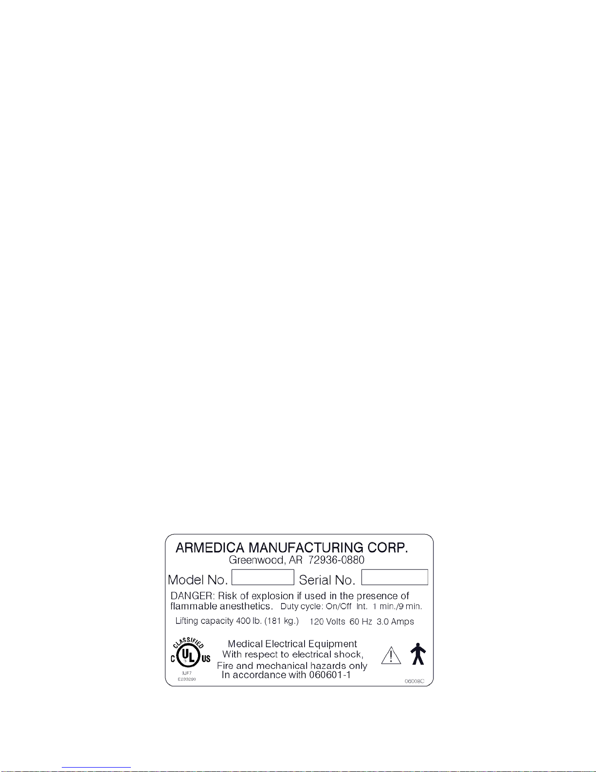
TABLE LIFTING CAPACITY: 400 LBS. (181 KILOGRAMS)
Magnetic Corp., Olney, Illinois 62450 Model
MAX 65-A200415A1001-000. Rated Voltage
and Frequency 120V 60HZ. Current 1.8 Amps.
UL CORD SET 140-355 Duty cycle: on/off Int.
1 min. / 9 min. Micro switch model E13-00K
Transport and Storage
Ambient Temperature: -20 to 70 deg. C
Relative Humidity: 10 to 100%, including
condensation
Atmospheric Pressure: 500hPa to 1030hPa
MOTOR SPECIFICATIONS

PARTS LIST
ITEM NO. PART NO. DESCRIPTION QUANTITY
150 200 300 350 400 500
250 450 550
102005 BOLT SHLDR 5/16x3/4 26246
202015 BOLT SHLDR 1/2x1/2 888888
302020 BOLT SHLDR 1/2x2 222222
402026 BOLT SHLDR M10X50 222222
502030 BOLT CARRIAGE 1/4-20x2 1 1
602035 SCREW BTN HD SOC 5/16-18x1-1/2 26446
702037 SCREW BTN HD SOC 1/4-20x1 1
802042 SCREW BTN HD SOC 1/4-20x1/2 2
902044 SCREW HX HD CAP 1/4-20x1-1/4 4
10 02045 SCREW HX HD CAP 1/4-20x1 1 14 1
11 02049 SCREW HX HD CAP 3/8-16x3
12 02050 SCREW HX HD CAP 5/16-18x1-3/4 2
13 02054 SCREW HX HD CAP 1/4-20x1-3/4 4
14 02065 SCREW HX WASHER HD #14x1 10 14 14 4 14
15 02070 SCREW HX WASHER HD #14x1-3/4 6
16 02073 SCREW FLT HD PHIL 1/4-20x1-1/2 2
17 02075 SCREW HX WASHER HD #14x2-1/2
18 02077 NUT NYLOCK 6-32 888888
19 02089NUT NYLOCK 10-32 1
20 02090 NUT NYLOCK 1/2-13 1 1 1
21 02092 NUT NYLOCK M8-1.25 HEAVY 222222
22 02095 NUT NYLOCK JAM 1/2-13 2
23 02097 NUT HX FIN 10-32 2
24 02099 SCREW PAN HD PHIL 10-32x1-1/4 1
25 02100 NUT NYLOCK 1/4-20 2 4 10 6 10 10
26 02101 SCREW PAN HD PHIL 10-32x1 1
27 02105 NUT NYLOCK 5/16-18 26446
28 02110 NUT NYLOCK 3/8-16 222222
29 02120 NUT HX FIN 1/4-20 4 4
30 02135 NUT HX FIN JAM 1/2-13 26446
31 02140 WASHER 1/4 222222
32 02143 WASHER FENDER 1/4"IDx1"OD 2
33 02145 WASHER 1/2 1 1
34 02150 WASHER 5/16 4
35 02160 WASHER NYLON 5/16 ID 4 12 8 8 12
36 02162 SPACER PLAS .33 IDx.565 ODx.56 2 2
37 02165 WASHER NYLON 1/2 ID 10 10 11 8 11 11
38 02166 SPACER NYLON 1-1/4ODx17/64IDx3/4
39 02168 SPACER NYLON .980 ODx.352 IDx1/2 4
40 02170 PIN SPRING 3/16x1 26466
41 02175 PIN SPRING 1/4x1-1/2 2
42 02176 SCREW BTN HD SOC 3/8-16X3/4 222222
43 02188 BOLT SHLDR 5/16X1-1/4 2
44 02204 CABLE TIE ADHESIVE MOUNT
45 02235 CABLE TIE 1/16" X 6"
46 02449 WIRE WX1015 VIOLET
47 02450 WIRE WX1015 BLUE
48 02453 WIRE WX1015 GRAY
49 02476 PLT CVR FRMD 1-3/8x4-1/2x9-7/8 PNTD 111111

150 200 300 350 400 500
250 450 550
50 02478 PLATE FORMED SWITCH MNT PNTD 1 1 1 1 1 1
51 02528 SPACER PLAS .775 ODx.515 IDx.250 RL 4 4 4 4 4 4
52 02538 SCREW BTN HD SOC 1/4-20x3/4 2 2 2 2 2 2
53 02645 BOLT SHLDR 1/2x1 2 2 2 2 2 2
54 02646 BOLT SHLDR 1/2x1-1/4 2 2 2 2 2 2
55 02647 SPACER PLAS .251 ODx..152 IDx.156 8 8 8 8 8 8
56 02657 PLUG RD 1"ODx14-20 GA BLK 4 4 4 4 4 4
57 02660 NUT ACORN 1/2-13 NICKEL PLATED 4 4 4 4 4 4
58 02661 WASHER LOC 1/2" INTERNAL TOOTH PLTD 4 4 4 4 4 4
59 02662 SPACER PLAS .620 ODx .504 IDx 13/16 2 2 2 2 2 2
60 03005 PLUG 1/2x1x14GA 4
61 03006 TUBE HEAT SHRINK 1/8"
62 03007 TUBE HEAT SHRINK 3/32"
63 03008 PLUG 1x1-1/2 2
64 03010 PLUG 1x1x14GA 2 2 2 2 4 2
65 03013 CAP .312x4 BLK PLASTIC TUBE 2
66 03015 PLUG 1x2x14GA 8 8 8 8 9 8
67 03019 CAP 3/8 BLACK 2 2
68 03020 PLUG 1-1/2x2-1/2x11GA 4 4 4 4 4 4
69 03025 SPRING TORSION RH 2 1 1 2
70 03030 SPRING TORSION LESS BEND RIGHT 1 1 1 1 1
71 03035 SPRING TORSION LH 2 1 1 2
72 03040 SPRING TORSION LESS BEND LEFT 1 1 1 1 1
73 03065 GLIDE 1/4-20x1 4 2 4
74 03066 BEARING KILLIAN F300 1/2 ID 1-1/8 4
75 03070 KNOB WING 1/2X13 ID 2 6 4 4 6
76 03073 KNOB PULL 1/2-13 ID 2
77 03080 RIV NUT 1/4-20 14GA 4 2 4
78 03095 SPRING M30 EXTENSION 1 1
79 03096 SPRING M52 COMPRESSION ARM REST 2
80 03105 MOTOR MAX65 8000N 120V 1 1 1 1 1 1
81 03107 CORD PWR MAX65 MTR 8000N 1 1 1 1 1 1
82 03125 KNOB "T" SPRNG LOAD PULL PIN 1/4DIA 1
83 03178 CASTER DTCAS 4" DUAL LOCK 4 4 4 4 4 4
84 03190 TERM GS INSUL NYLON FEMALE 22-18GA 8 8 8 8 8 8
85 03191 SWITCH LIMIT ROLLER FT RAIL E13-00K 4 4 4 4 4 4
86 03192 STRAIN RELIEF FT RAIL SWTCH COVER 1 1 1 1 1 1
87 03193 RIVET PLAS PUSH FT RAIL COVER BLK 2 2 2 2 2 2
88 03214 UHMW 1x1/16 TOT BK FT HOOK SPACER 2
89 03263 TERMINAL BLOCK 12 POLE 18-20GA 350V 1 1 1 1 1 1
90 03283 CABLE MAX65 FT BAR CONTROL 2.55M 1 1 1 1 1 1
91 03429 SPRING COMPRSSN 3/4x1-5/8 ZINC PLTD 2 2 2 2 2 2
92 12311 BAR GEAR 1/2SQx7-3/4 AT LOCK PLTD 1
93 12511 BAR 1/8x1x2-3/4 STRAP HOOK 400 PLTD 2
94 12519 GEAR RACK PLUNGER LOCK PLTD 1
95 12527 BAR 1/8x1-1/4x2-13/16 LOCK LINK PLT 1
96 12751 PLATE SX 1/8x6-1/2 STND LOCK PLTD 1
97 13016 ROD 1/2x21 THD'D HD SEC LOCK PLTD 1 1 1 1 1
98 13021 ROD 1/2DIAx23 THD'D CTR SEC LK PLTD 1 1
99 02252 SCREW PAN HD PHIL 10-24x1/2 2 2 2 2 2 2
100 02207 WASHER SEALED #10x1/2 GALV STEEL 2 2 2 2 2 2
101 02265 SHT MTL AM-BA SIDE SHIELD PNTD 2 2 2 2 2 2
PARTS LIST
QUANTITY
ITEM NO.
PART N O.
DESCRIPTION

150
200
300
350
400
500
250
450
550
99 13026 ROD 1/2x23 THD'D FT SEC LK PLATED 1 1 1
100 13095 SPACER .913ODx.635 IDx.641 WHT PLAS 2 2 2 2 2
101 13504 ROD 1/2x17-1/4 FT SEC 400 THD PLTD 1
102 13521 ROD 1/2x23 THD'D 400 CAM LOCK PLTD 1
103 13526 BUSH CAM .515 ID LOCK MECH PLTD 1
104 14501 BD UPH AM400 18x27 THORACIC 1
105 14502 BD UPH AM400 10x27 LUMBAR 1
106 14503 BD UPH AM400 33x27 FOOT SECTION 1
107 14508 BD PLY 400 ADAPT FORMICA 3/4x10x12 1
108 14800 BD UPH ARMREST 500 RIGHT 1
109 14801 BD UPH ARMREST 500 LEFT 1
110 14802 BD UPH 500 HEAD 1
111 14812 BD UPH HD SEC 27" WIDE 1 1 1 1 1
112 14813 BD UPH CTR SEC 27" WIDE 1 1 1
113 14814 BD UPH FOOT SEC 27" WIDE 1 1 1
114 14826 BD UPH 200 BODY 27" 1
115 14827 BD UPH 100 TOP 27" 1
116 18111 LIFTING ARM FOOT PAINTED 1 1 1 1 1 1
117 18113 LIFTING ARM HEAD PAINTED 1 1 1 1 1 1
118 18115 FRAME HEAD SECTION PAINTED 1 1 1 1 1
119 18117 FRAME 300 CENTER SECTION PAINTED 1 1
120 18127 BRKT LOCK SUPPORT PLATED 2 6 4 4 6
121 18136 FRAME TOP 100 PAINTED 1
122 18138 FRAME TOP 200 PAINTED 1
123 18144 BAR 300 CTR SEC LOCK S/A PLATED 1 1
124 18150 FRAME HEAD SECTION 500 PAINTED 1 1 1
125 18152 BRKT ARMREST 500 LEFT PLATED 1 1 1
126 18154 BRKT ARMREST 500 RIGHT PLATED 1
127 18184 CONTROL ROD 1 PC PNTD 1 1 1 1 1 1
128 18446 ROD 1/2x11-11/16 HD SEC SPPT PLTD 2 2 2 2 2
129 18448 ROD 1/2x8-11/16 CTR SEC SPPT PLTD 2 2
130 18452 ROD 1/2x18 400 TRAC FT SPPT PLTD 2 2 2
131 18494 STAND MACHINE PIVOT BC PAINTED 1
132 18496 ROD 1/2x15-3/4 400 FT SEC SPPT PLTD 2
133 18501 FRAME TOP ROLLER 400 PAINTED 1
134 18506 FRAME FOOT SEC 400 PAINTED 1
135 18512 FRAME TOP 400 TRACTION PAINTED 1
136 18516 HANDLE FT BD 400 LK RLSE RT PLATED 1
137 18522 HANDLE FT BD 400 LK RLSE LFT PLTD 1
138 18914 BASE AMB 4 CSTR PNTD 1 1 1 1 1
139 18921 FRAME TOP 350 RR PNTD 1 1
140 18923 FRAME TOP 300 RR PNTD 1 1
141 18925 FRAME FOOT SECTION RR PNTD 1 1 1
142 18927 BAR FOOT SWITCH BC BASE PNTD 2 2 2 2 2 2
143 18953 BASE BC TRACTION 400 PNTD 1
144 19020 PLATE FRMD SWITCH MNT ASSEMBLED 1 1 1 1 1 1
145 02252 SCREW PAN HD PHIL 10-24x1/2 2 2 2 2 2 2
146 02265 SHT MTL AM-BA SIDE SHIELD PNTD 2 2 2 2 2 2
147 02207 WASHER SEALED #10x1/2 GALV STEEL 2 2 2 2 2 2
ITEM NO. PART NO. DESCRIPTION
PARTS LIST QUANTITY

127
117
68
83
116
64
3
37 2
53
49
51
58
138
52
31
25
91
144
4
81
80
142
56
54
59
57
21
66
28
42
TABLE BASE
AM-BA SERIES

66
121
15
2
37
115
TOP FRAME
AM-BA100
TOP FRAME
AM-BA200
114
37
2
1
97
122
70
40
120
35
128
118
27
72100
6
30
25
75
66
14
111

99
113
73
66
77
2
37
141
75
20 35
29
10
123
130
78
5
33
6
69
129
97
100
70
119
140
14
118
72
40
128
25
1
27
120
71
98 67
111
30
112
TOP FRAME
AM-BA300

99
113
73
66
77
130 141
27
40 139
30 75
71
69
120
1
2
97
43
70
36
14
128
118
72
35
6
100
37
25
111
112
TOP FRAME
AM-BA350

1
34
105
40
137
25
74
106
71
10
133
134
27
132
6
69
120
136
101
65
22
16
92
39
13
37
64
30
102
24
26
95
94
135
10323
7
97
100
70
19
118
128
93
14
35
72
66
111
75
104
2
TOP FRAME
AM-BA400

63
20
10
107
131
82
37
12
66
96
36
25
143
SWIVEL STAND
AM-BA400, 450
HEAD PIECE
AM-BA250, 450, 500, 550
97
30
108
120
76
70
6
8
32
79
9
126
128
41
124
27
35
14
125
110
60
109

MICRO SWITCHES
The bar activated treatment table is equipped with 4 micro switches located in the box
mounted on the foot end of the base. The switches are designed to provide years of
reliable service. In the rare case that a switch does become inoperative, the box at the end
of the table must be accessed. The switches are low voltage and are not a shock hazard.
However caution should be used while servicing. The wires connecting the terminals to the
switch are light gage and easily damaged. To replace a micro switch, follow these
instructions while referring to switch box and wire diagram drawings.
DISCONNECT THE TABLE FROM THE WALL OUTLET BEFORE REMOVING SWITCH
1. Remove the cover plate (49) by removing 2 screws (145) from the top and 2 black
plastic reusable rivets (87) from the bottom. Carefully slide the blade of the screw driver
under the head of the rivet so damage to the finish does not occur. The head of the rivet
will pop up allowing it to be removed. DO NOT DISCARD RIVETS.
2. Using both hands, gently remove cover plate by pulling directly away from mounted
switch plate (50).
3. After determining which micro switch is not functioning by pushing or pulling on the foot
bar, disconnect the table from the power source.
4. Using a 5/16” wrench remove two nuts (18) from the threaded studs and carefully
remove the switch taking care not to damage the wires connected to it.
5. Remove the terminals from the switch by gently tugging on them. DO NOT PULL WIRE.
6. After the micro switch is disconnected, reconnect the replacement switch referring to the
wire diagram found in this manual making certain the terminals are securely connected.
7. Once the wire terminals are connected to the replacement switch, make sure the plastic
spacers (55) are on the threaded stud prior to reinstalling replacement switch.
8. Replace nuts (18) and securely tighten taking care not to over tighten.
9. Reconnect table to power source and test. Providing the table is operating correctly,
replace cover plate ensuring that the side shields (146) are in place and reusing the
screws, washers and plastic rivets.

BLUEBLUE
BLUE
PURPLE
PURPLE
GRAYGRAY
GRAY GRAY
GRAY
PURPLE
CORD TO MOTOR
DOWN
UP
86
90
89
50
85
55
18
84
87
49
147
145
146
OPEN
CLOSED
SWITCH BOX
AM-BA SERIES
WIRE DIAGRAM
14
ARMEDICA™ MANUFACTURING CORP.
LIMITED WARRANTY
ARMEDICA™ Manufacturing Corp. warrants that the AM Series treatment tables are free from
defects in material and workmanship. This warranty shall remain in effect for 18 months from
the date of original consumer purchase of the product. If the product fails to function during the
warranty period due to a defect in material or workmanship, ARMEDICA™ Manufacturing Corp.
or the selling Dealer will repair or replace the table without charge within a 30 day period from
the date on which the table is returned to ARMEDICA™ Manufacturing Corp. or the selling
Dealer.
THIS WARRANTY DOES NOT COVER
1. Replacement parts or labor furnished by anyone other than ARMEDICA™,
Selling Dealer or approved ARMEDICA™ Service Agent.
2. Any failure of the table during the warranty period if the failure is not caused by a defect
in material or workmanship or if the failure is caused by unreasonable use, including the
failure to provide reasonable and necessary maintenance.
ARMEDICA™ MANUFACTURING CORP. IS NOT LIABLE FOR INCIDENTAL
OR CONSEQUENTIAL DAMAGE TO PROPERTY OR BUSINESS.
To obtain service under this warranty, please do the following:
1. A written claim should be sent to ARMEDICA™ Manufacturing Corp., P.O. Box 880,
Greenwood, AR. 72936-0880 or the selling Dealer.
2. The table must be returned to ARMEDICA™ Manufacturing Corp. or the selling Dealer.
3. This warranty gives you specific legal rights and you may have other rights, which vary
from state to state
ARMEDICA™ does not authorize any person or dealer to create for it any other obligations or
liabilities in connection with the sale of the tables. Any representation or agreement not
contained in this warranty shall be void.
PN-03431 REV. F 2/20/15
AM-BA SERIES MANUAL
15
Other manuals for AM-BA Series
1
This manual suits for next models
9
Table of contents
Other Armedica Medical Equipment manuals

Armedica
Armedica AM Series User manual

Armedica
Armedica AM-SX Series User manual

Armedica
Armedica AM Series User manual

Armedica
Armedica AM-BA Series User manual

Armedica
Armedica AMTM-700 Series User manual

Armedica
Armedica AM-700 Series User manual

Armedica
Armedica AM-702 User manual

Armedica
Armedica AM-SX Series User manual


