Armedica AM-702 User manual

This manual has been prepared for the owners and operators of
the ARMEDICA™ AM-700 Series Parallel Bars and
contains installation instructions, precautionary instructions
and maintenance procedures for the following model numbers:
AM-700, AM-702, AM-703,
AM-705, AM-706, AM-706HD

This User's Manual is for the following AM-700 series Parallel platforms only
AM-700 - Electric platform mount 10'x43"
AM-702 - Electric platform mount 7'x43"
AM-703 - Electric platform mount 15'x43"
AM-705 - Electric bariatric platform mount 10'x49-1/2"
AM-706 - Electric bariatric platform mount 10'X49-1/2"
AM-706HD - Electric bariatric platform mount 10'x49-1/2" with 11GA. hand rails
Table of Contents
Models covered in manual and table of contents 2
Symbols and Indicators 3
Definitions 4
Assembly and Installation 6
Operating instructions 9
Maintenance 10
Cleaning 11
Technical specifications 12
Parts list and Drawings 13
Maintenance Log 23
Warranty information 24
IMPORTANT: Do not use this manual to reference instructions, requirements or
specifications for any product other than those listed in this manual.
Equipment damage, void of warranty and personal injury may occur.
WARNING: Read and understand this user's manual before installing or using this
equipment.
Failure to follow operating and maintenance instructions could result in equipment
damage or personal injury.

SYMBOLS and INDICATORS
WARNING: Follow safe lifting procedures and precautions.
ATTENTION: Important information or instructions.
Type B Applied part: An Applied Part complying with the specified requirements to
provide protection against electric shock, particularly regarding allowable patient
leakage current and patient auxiliary current.
WARNING: Identifies electrical shock hazard.
This platform is equipped with a protective earth ground. This device may only be
connected to a power source with a protectively earthed ground.
WARNING: Read and understand the operating instructions listed in this manual
before installing or using this equipment.
Failure to follow manufacturer's operating instructions could result in equipment
damage or personal injury.
Alternating Current
2

DEFINITIONS
The AM-700 Series Electric Parallel Bars are a Class 1 medical device in respect
to the use of an earthed ground as a means of protection against electric shock.
Intended use: The AM-700 Series Electric Parallel Bars is intended for medical
rehabilitation purposes and, to be used in conjunction with other forms of
exercise, as a stability aid in standing, walking and balance exercises.
Patient: Any person cleared by a doctor or physical therapist currently using this
device as an exercise platform under the direction and supervision of a qualified
operator.
Operator: Any person/persons who is a professionally trained and certified
physical therapist and authorized by the consumer or responsible organization to
operate this platform. Specific instructions for operation of the AM-700 series
can be found in this manual. If further training on the operation of the AM-700 is
required, it is available by contacting Armedica Mfg. customer service.
Service Technician: Any person/persons authorized by Armedica Manufacturing
to perform service, component replacement or repair to the AM-700 Series
Electric Parallel Bars.
CAUTION: A patient is not intended to operate this device in any
way. The AM-700 series Electric Parallel Bars shall be operated
by trained, qualified and authorized personnel ONLY.
CAUTION: Using this device in a manor inconsistent with its
labeling will void warranty and, damage to device or personal
injury may occur.
CAUTION: This device is not suitable for use in an oxygen rich
environment or in the presence of flammable anesthetics. Fire or
explosion may occur.
3

DEFINITIONS CONTINUED
Duty Cycle: The ratio of time the device can be in a state of continuous actuation
(moving) and rest. Noted in units of minutes as ON/OFF. The Duty Cycle of this
device is rated for 1(one) minute on / 9(nine) minutes off.
Electrical power source: This platform is intended to be connected to an external
120V , 8 Amp (peak), 60Hz electrical power source.
Applied part: An applied part is one specifically intended to come into direct
contact with patient during normal use. This includes Armedica part #'s 18628,
28320, 18627, 14601, 14605, 14609, 14610 and 14615 only. Applied parts are
identified, either in this manual or directly on the part, with this symbol .
Accessible Part: An Accessible Part is any part that the patient or operator may
come into direct contact with, either intentional or unintentionally, but direct
contact is not required for normal operation.
Operator Interface: The point in which the operator will input data, via momentary
push button, for actuation, memory function and device control.
WARNING: To avoid risk of electrical shock, this device must
only be connected to a supply mains with protective earth
ground.
4

AM SERIES ELECTRIC PARALLEL BARS
ELECTRIC PARALLEL BARS INSTALLATION
ALL MODELS
1. Remove platform (item # 1, 46, 47 or 51) from crate using handles attached to mounting
brackets. Set the platform on firm level floor.
For 2-piece split platforms, set both pieces on side against a solid surface while installing
connecting plates (50). Align the 2 pieces and firmly hold together. Using screws (49),
install all connecting plates in recessed pockets. After all, connecting plates have been
installed, place platform on floor as directed in step 1.
2. Place the four upright columns (13) between the brackets on the platform according to
letter designations and tighten the mounting bolts (10) securely.
3. Install the hand rails (30, 44 or 45) onto the adjustment tubes (4) using spacer (31),
washers x2 (32), and lock nut (35); tighten the lock nut (35), sufficiently, to eliminate any
play but not so tight that they will not pivot when adjusting the width. When necessary,
adjust the width according to the operating instructions.
4. Remove the cover plate from box (23) to allow access to inside of control stand (20).
Using nuts (21), mount the control stand (20) to the platform, threading AC mains cable, 4
protective earth ground wires (green with yellow), and connector cables (36, 37 and 42)
through appropriate holes. Ensure all protective earth grounds are secured on the bolt pin
with paint removed.
5. With screws (26) and cover plate (24) removed, connect the controller (22) per the
following instructions.
WARNING: Read and understand this operator’s manual before
installing or using this equipment.
Failure to follow operating and maintenance instructions could result
in equipment damage or personal injury.
WARNING: 4 people are required to move this equipment.
This unit weighs in excess of 500lbs/1100kg. Failure to follow safe
lifting instructions can result in serious personal injury and/or damage
to equipment.
CAUTION: There are no contradictions associated with this
device. The emissions characteristics of this device make it
suitable for use in industrial areas and hospitals.
CAUTION: Do not lift or support by end ramps or columns. Damage t
or serious personal injury may occur
5

SCU CONTROLLER
1. SCU CONTROLLER
2. AC MAINS PORT
3. SWITCH PORT
4. PROTECTIVE EARTH
TERMINAL
5. MOTOR PORT M1
6. MOTOR PORT M2
7. MOTOR PORT M3
8. MOTOR PORT M4
CAUTION: All cables must be fully inserted into their appropriate
receptacles on control box and columns. Failure to do so may cause
unit malfunction and/or permanent damage to equipment.
WARNING: Dangerous voltage present.
Do not connect this unit to a power source before reading these
instructions. Damage to equipment and/or electrical shock may
occur.
WARNING:
This device may only be used in a professional healthcare
facility where operators with professional medical training are
continuously available when patients are present.
WARNING: Do not adjust or operate this device while patient is on or
using this device. Serious personal injury and/or damage to
equipment may occur.
1
2
3
4
5
6
7
8
6

CABLE CONNECTIONS
•Connect the four cables (36) and (37) (DIN8 connectors) to the appropriate column (13).
•Remove cover from the lower section of the SCU controller by rotating the lock screw,
located on the front of the cover, to the “UNLOCK” position. Slide cover down to remove.
•Connect the four cables (36) and (37) (DIN8 connectors) to corresponding SCU controller
motor ports M1, M2, M3 and M4 (AS LABLED)
•Verify that the control switch (27) cable with a blue DIN7 socket marked with a blue “HS” is
securely connected in the switch port
•Securely connect the AC mains cable (42) into the AC mains port of the SCU controller.
•Verify that the required supply voltage indicated in this manual and on the name plate
corresponds with the supply voltage of the electrical outlet and connect the unit to the
electrical outlet. *See Technical Data section for a full list of operating conditions and
requirements.*
CAUTION: This device is rated for 120 volts
60Htz, 6.5Amps/8Amps peak. Protective
earth ground required.
ATTENTION: Allow 10 seconds, after
connecting to power supply, for system to
fully initialize and display reads “028”before
attempting any operations. See figure
below.
7

ELECTRIC PARALLEL BARS OPERATING INSTRUCTIONS
ALL MODELS INTENDED POSITIONS
This unit has been initialized by Armedica Manufacturing Corp. prior to shipment and
should not need to be synchronized again unless a column or control box is replaced.
If Synchronization becomes necessary, follow these steps:
INITIAL RESET FOR MOTORS
•After you have connected the control units to the power supply for the first time, the
network is addressed, and motors must be synced. This is indicated by "---" remaining on
the display after approximately 10 seconds.
•Press and hold 1+2+UP BUTTON for 5-10 seconds then you will hear a audible click,
then beeps. Release buttons, beep stops.
•Press and HOLD the down ARROW key. All 4 columns should lower at a reduced speed.
Continue to hold the key until the columns reach their lowest point and, you hear an
audible click. Wait three seconds and display should show the current height.
SETTING THE PARALLEL BAR HEIGHT
•Press the up arrow to raise the parallel bars.
•Press the down arrow to lower the parallel bars.
•The current height of the bars appears (in inches) on the display.
SAVING THE MEMORY POSITIONS
This function makes it possible to save a predetermined height setting. Four different heights
may be saved. These saved positions can be used later.
•Adjust the bars to desired height by using the UP or Down arrow keys.
•Press the green memory key (S) and release. Press the desired memory key (1, 2, 3 or 4).
An audible click signals the position is now saved to that number.
WARNING: Ensure platform is clear and, there are no obstructions
under the handrails before actuating the columns to adjust height.
Serious personal injury and/or damage to equipment may occur.
Operator position
Patient position
8

USING THE MEMORY POSITIONS
•While holding down the desired memory position button, the bars will move toward the
predefined position and stop.
ADJUSTING THE WIDTH OF THE PARALLEL BARS
•Turn hand knobs, on top of each column, to release adjusting tubes and set to desired
width.
•
Make sure adjusting tube knobs are securely tightened before use.
MAINTENANCE
ARMEDICA™ Manufacturing thoroughly inspects and tests each unit to ensure that it
meets all ARMEDICA™ quality standards before it leaves the facility. To ensure the
longevity of your device, routine maintenance should be followed.
AFTER FIRST 40 HOURS OF SERVICE
Physically inspect all fasteners and hardware are properly secured
DAILY / Pre-USE
The operator should visually inspect the unit prior to each use for;
Foreign objects that may interfere with operation or create a hazard to patient
Signs of damage to unit and power cord
All hardware (nuts, bolts, etc.) is present and properly secured
All adjustments are secure
Unit functions properly
CLEANING
Use towel dampened with mild soap and water. Wipe down to remove dust, dirt and spills.
Wipe with dry towel to remove moisture
Laminated platform
Painted, plated and plastic surfaces
Use a commercial brand stainless steel cleaner to remove dirt and oil from hand rails
The laminated platform and painted or plated components should be cleaned with a
commercial disinfectant and wiped with a dry cloth to remove any biological contamination
when necessary.
CAUTION: Failure to follow recommended maintenance instructions
may cause damage to equipment, personal injury and void warranty.
WARNING: This unit is not rated for wash down, it should not be
exposed to standing or quantities of liquid.
Do not clean any electronic device with water. Electrical shock and/or
damage to electronics may occur.
9

TROUBLE SHOOTING
In the event it becomes necessary to replace the control box or a column on the AM-700 series,
disconnect power prior to removal, and make certain the plugs are completely inserted into the
sockets prior to reconnecting power.
ELECTRIC POWERED COLUMNS DO NOT WORK.
A. Verify that proper voltage at electrical outlet and cord is plugged in.
B. Verify all cables inside the control stand and motor columns are securely plugged into their
proper receptacles.
C. Verify the hand switch cable is securely plugged into the proper control unit.
If problem still occurs, or columns become unsynchronized, please contact Armedica
Manufacturing Customer Service.
ATTENTION:
The AC Mains Cable serves as the
EMERGENCY DISCONNECT DEVICE
Do not position this device in a manner that would make it difficult to
reach the AC mains supply cable. In the event of an emergency,
unplug the AC Mains Cable from the external power supply.
WARNING: Disconnect main power to unit before opening control
stand and checking cables. Electrical shock and/or damage to
electronics may occur.
CAUTION: Service to controls and column motors is to be done by
the manufacturer only. In the event of a column motor or control unit
failure, all 4 columns and control unit must be returned to Armedica
Manufacturing Corp.
WARNING: Do not alter or modify this device in any way. Altering
this device will void all warranties. Serious personal injury and/or
damage to equipment may occur.
WARNING: Use only replacement parts approved by Armedica
Manufacturing. Failure to do so could result in damage to device,
increased emissions, immunity/susceptibility to such and serious
injury. A list of specific authorized replacement parts, including
cables and other critical components, is provided on page 15 of this
manual.
10

TECHNICAL SPECIFICATIONS
ENVIROMENTAL CONDITIONS
Operating/storage temp. 5°C – 40°C / 41°F – 104°F
Humidity: 5% to 85%
Pressure/altitude: 700hPa to 1060hPa
GENERAL SPECIFICATIONS
Manufactured and assembled by
Armedica Manufacturing Corp.
Greenwood, Arkansas, USA
Tel.: (479) 996-2612
Static & Dynamic load capacity
Max 500Lbs/227Kgs per bar, not exceeding 500Lbs/227Kgs total combined load.
ELECTRICAL SPECIFICATIONS
Main input power requirements 120VAC 60Hz
Current 6.5Amps / 8Amps (peak)
Secondary output power 24VDC / 360V/A
Duty cycle 1min. on / 9min. off
Model SCU56-003230-000
Manufactured by:
SKF Actuation Systems
Oristalstrasse 97
CH-4410 Liestal
Tel.: +41/61/925 41 41
Email: actuators.switzer[email protected]
CAUTION: Do not exceed Maximum load capacity. Damage to unit
and/or serious injury may occur. This device is not rated for a
dynamic(moving) load. Do not use as a patient lift.
CAUTION: Do not throw in trash. Expected service life of this device
is approximately 10 years. Dispose of this device in accordance
with local, state and national environmental regulations. Failure to
do so may constitute a criminal act.
11

ITEM NO. PART NO. DESCRIPTION QUANTITY
MODEL NUMBERS
700 702 703 705 706 706HD
1 14601 BD PLL COLMN PLATFORM LAMNTD
1N/A N/A N/A N/A N/A
2 28156 PLATE 1/4x4-3/4x6-1/2 PLL COLMN MNT PLTD 44444 4
3 03021 SCREW TAPTITE M6X2
5
16 16 16 16 16 16
4 11601 TUBE 1x1x14GAx13 PLL RAIL ATTAC
H
44444 4
5 02146 SPACER 5/16 X 3/16 ID x 1/2 OD 44444 4
6 02093 NUT NYLOCK 8-32 44444 4
7 13601 ROD 1/2 DIAx.75 PLUNGER 44444 4
8 03071 KNOB W/STEM 2-1/4x3/8-16x1 44444 4
9 02033 NUT HEX M8-1.25Z 16 16 16 16 16 16
10 02031 SCREW HEX HD 8MM-1.25x14Z 16 16 16 16 16 16
11 03076 CAP PLAS BLK 5/16 HEX DOM
E
16 16 16 16 16 16
12 18593 BRKT PLL RAIL ADJ RT PLT
D
22222 2
13 03181 TMD PLL COLUMN ONLY 44444 4
14 02105 NUT NYLOCK 5/16-18 16 16 16 16 16 16
15 28042 BRKT PLL COLUMN MNT W/HANDLEPLTD 4 4444 4
16 12633 ANG 1x1x6-1/4 PLL CLMN MNT PLTD 44444 4
17 18665 BUSH W/WASHER PLL PIN GUIDEPLTD 2 2222 2
18 02063 SCREW HX WASHER HD #10x3/
4
38 38 38 38 38 38
19 28040 BRKT PLL PLTFRM CONTROL STANDMNT 1 1111 1
20 18672 TUBE PLL CTRL STAND S/
A
11111 1
21 02100 NUT NYLOCK 1/4-20 44444 4
22 03556 CONTROL SCU PLL 11111 1
23 03078 BOX 4-5/16x17x14GA SHT MTL PLL 11111 1
24 03078 PLATE 8-1/4x16-15/16x14GA COVER SKF PLL 1 1111 1
25 03080 RIV NUT 1/4-20 ALUMINUM 14GA 44444 4
26 02538 SCREW BTN HD SOC 1/4-20x3/4 44444 4
27 03183 SWITCH PLL TMD CONTRO
L
11111 1
28 02040 NUT HX 5-40 MACH SCR
W
33333 3
29 18598 BRKT PLL RAIL ADJUST LEFT PLT
D
22222 2
30 18628 TUBE STAINLESS PLL RAIL S/A
2N/A N/A 2 2 2
31 13056 BUSHING 1/2IDx3/4ODx1-1/8 CNTRL BUSH 4 4444 4
32 02165 WASHER NYLON 1/2 I
D
88888 8
33 03010 PLUG 1x1x14G
A
88888 8
34 03014 PLUG RD 1"ODx14-20 GA BLK 44444 4
35 02095 NUT NYLOCK JAM 1/2-13 4444 4 4
36 03184 CABLE TMD CONNECT LONG 8F
T
22222 2
37 03185 CABLE TMD CONNECT SHORT 4'-10
"
22222 2
38 02148 BUSHING INSUL NYLON PLL 4444 4 4
39 03364 LD SWITCH ADAPTE
R
11111 1
40 02107 SCREW PAN HD PHIL 8-32x3/4" 44444 4
42 03365 CBL 3.6M MED UL PWR CORD SCU 1111 1 1
43 02201 CLAMP CABLE 1/4 WHIT
E
30 30 30 30 30 30
44 18627 TUBE STAINLESS 15' PLL RAIL S/A N/A N/A 2 N/A N/A N/A
45 11607 TUBE SS PLL 1-1/2 DIAx14GAx7'-6" N/
A
2N/
A
N/
A
N/
A
N/
A
46 14609 BD PLL 7FT COLMN PLTFRM LAMNT N/A 1 N/A N/A N/A N/A
47 14610 BD PLL 15' SPLIT PLATFORM LAMN
T
N/
A
N/
A
1N/
A
N/
A
N/
A
48 02200 CLAMP CABLE 3/16 BLACK
N/A N/
A
12 N/
A
N/
A
N/
A
49 02695 SCREW #14x1 FLT HD PHIL WD N/A N/
A
16 20 20 20
50 12609 PLT 1/4x2x8 PLL SPLIT PLTFRM PNTD N/A N/
A
455 5
51 14615 BD PLL 10' PLTFRM BARIAT SPLIT W/E
C
N/A N/
A
N/
A
N/
A
11
52 14605 BD PLL COLMN PLATFORM BARIATRI
C
N/
A
N/
A
N/
A
1N/
A
N/
A
53 28320 TUBE STNLSS PLL 10' HD N/
A
N/
A
N/
A
N/
A
N/
A
2
54 02681 SCREW PAN HD PHIL 10-32x3/4 4 4 4 4 4 4
55 02144 WASHER FLAT #10
4444 4 4
56 03554 WIRE 74" PE GRND PLL COLUMN ASM 2 2 2 2 2 2
57 03555 WIRE 48" PE GRND PLL COLUMN AS
M
2222 2 2
58 02078 SCREW PAN HD PHIL 10-32x3/
8
4444 4 4
59 02493 TERM RING INSUL #10 STUD 22-18 AWG 4444 4 4
12

HEIGHT ADJUSTMENT
27" MINIMUM
TO
54" MAXIMUM
PATIENT
HAND RAIL
120" PLATFORM LENGTH
VARIES BY MODEL
43"
PLATFORM WIDTH
VARIES BY MODEL
WIDTH ADJUSTMENT
30" MAXIMUM
TO
14" MINIMUM
WIDTH ADJUSTMENT
LOCKING KNOB
OPERATOR INTERFACE
SWITCH
AM-700 SERIES
DIMENSIONS & ADJUSTMENT SPECIFICATIONS
13

29
10
14
11
15 36
8
4
33
3
6
5
40
21
20
1
30
35 32
31
34
12
29
44 45 53
46
47
51
52
37
16
7
AM-700 SERIES
ELECTRIC PARALLEL BARS
13
14

19
18
17
43
57
56 59
58
AM-700 SERIES
ELECTRIC PARALLEL BARS
BOTTOM VIEW
15

23
20
27
55
54
22
24
26
39
42
AM-700 SERIES
ELECTRIC CONTROL STAND
28
16

50
49
51
47
AM SERIES
SPLIT PLATFORMS
WITH END CONTROLS
ITEM NO.
PART NUMBER
DESCRIPTION
QTY.
51
EC14605Bs
BD PLY PLL CLMN BARIATRIC PLTFRM
1
50
12608A
PLT 1/4x2x8 PLL SPLIT PLTFRM CONN
PNTD
5
49
02695A
SCREW #14x1 FLT HD PHIL WD
20
4
18671E_cmplt
TUBE PLL CTRL STAND S/A
1
5
03183A
SWITCH PLL TMD CONTROL
1
6
28155A
PLATE 1/4x4-3/4x6-1/2 PLL COLMN
MNT PNTD
4
7
03021A
SCREW TAPTITE M6X25
4
8
11601C
TUBE 1x1x14GAx13 PLL RAIL ATTACH
4
9
02146A
SPACER 5/16 X 3/16 ID x 1/2 OD
4
10
02007A
SCREW HX WASHER HD #8x3/4
4
11
13601A
ROD 1/2 DIAx.75 PLUNGER
3
12
03071A
KNOB W/STEM 2-1/4x3/8-16x1
4
13
02033A
NUT HEX M8-1.25Z
16
14
02031A
SCREW HEX HD 8MM-1.25x14Z
6
15
03076A
CAP PLAS BLK 5/16 HEX DOME
15
16
18592A
BRKT PLL RAIL ADJ RT PNTD BLACK
2
17
03181A
TMD PLL COLUMN ONLY
4
18
02105A
NUT NYLOCK 5/16-18
16
19
28041A
BRKT PLL COLUMN MNT W/HANDLE
PLTD
4
20
12632B
ANG 1x1x6-1/4 PLL CLMN MNT PNTD
4
21
18664B
BUSH W/WASHER PLL PIN GUIDE
PLTD
2
22
02063A
SCREW HX WASHER HD #10x3/4
10
23
18597A
BRKT PLL RAIL ADJUST LEFT PNTD
BLACK
2
24
18628A
TUBE STAINLESS PLL RAIL S/A
2
25
13056A
BUSHING 1/2IDx3/4ODx1-1/8 CNTRL
BUSH
4
26
02165A
WASHER NYLON 1/2 ID
8
27
03010A
PLUG 1x1x14GA
8
28
03014A
PLUG RD 1"ODx14-20 GA BLK
4
29
02095A
NUT NYLOCK JAM 1/2-13
4
30
03184A
CABLE TMD CONNECT LONG 8FT
2
31
03185A
CABLE TMD CONNECT SHORT 4'-10"
2
32
02148A
BUSHING INSUL NYLON PLL
4
33
02201A
CLAMP CABLE 1/4 WHITE
4
17

47
SPLIT PLATFORMS WITH
END CONTROL
51
5049
18

AM-714
ABDUCTION BOARD
4
3
2
1
1
2
AM-715
BALANCE BEAM
ITEM NO.
PART NUMBER
DESCRIPTION
QTY.
1
14603A
BD PLL ABDUCTION 3/4X5X94
1
2 18667
BRKT YOKE PLL BD PIN PLTD
2
3 02044
SCREW HX HD CAP 1/4-20x1-1/4
2
4 02084
NUT NYLOCK JAM 1/4-20
2
ITEM NO.
PART
NUMBER
DESCRIPTION
QTY.
1
14604A
BD PLL BAL BEAM 2-1/2X5X80
1
2
13003A
SCREW 3/-16x3 MODIFIED 2-3/8 PIN
2
19
This manual suits for next models
6
Table of contents
Other Armedica Medical Equipment manuals
Armedica
Armedica AM Series User manual

Armedica
Armedica AM Series User manual
Armedica
Armedica AM-SX Series User manual
Armedica
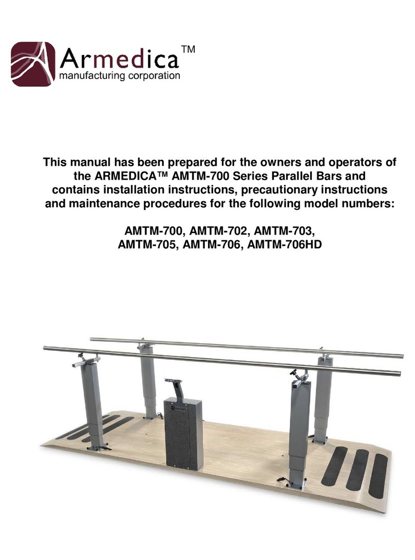
Armedica AMTM-700 Series User manual

Armedica
Armedica AM-SX Series User manual
Armedica
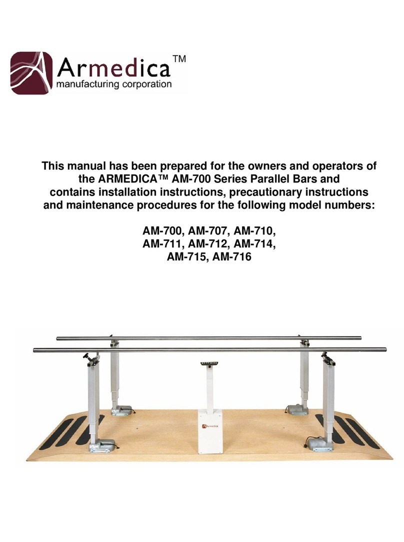
Armedica AM-700 Series User manual
Armedica
Armedica AM-BA Series User manual

Armedica
Armedica AM-BA Series User manual
Popular Medical Equipment manuals by other brands

Getinge
Getinge Arjohuntleigh Nimbus 3 Professional Instructions for use

Mettler Electronics
Mettler Electronics Sonicator 730 Maintenance manual

Pressalit Care
Pressalit Care R1100 Mounting instruction

Denas MS
Denas MS DENAS-T operating manual

bort medical
bort medical ActiveColor quick guide

AccuVein
AccuVein AV400 user manual


